Table of Contents
Advertisement
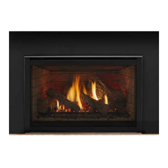
Models:
QFI30FB-C
QFI35FB-C
• Important operating
a n d m a i n t e n a n c e
instructions included.
WARNING:
FIRE OR EXPLOSION HAZARD
Failure to follow safety warnings exactly
could result in serious injury, death, or
property damage.
• DO NOT store or use gasoline or other fl am-
mable vapors and liquids in the vicinity of this
or any other appliance.
• What to do if you smell gas
- DO NOT try to light any appliance.
- DO NOT touch any electrical switch. DO
NOT use any phone in your building.
- Leave the building immediately.
- Immediately call your gas supplier from
a neighbor's phone. Follow the gas sup-
plier's instructions.
- If you cannot reach your gas supplier, call
the fi re department.
• Installation and service must be performed
by a qualifi ed installer, service agency, or the
gas supplier.
In the Commonwealth of Massachusetts installation must be
performed by a licensed plumber or gas fi tter.
A CO detector shall be installed in the room where the
appliance in installed.
R
NOTICE
DO NOT DISCARD THIS MANUAL
• Read, understand and follow
these instructions for safe
installation and operation.
Quadra-Fire • QFI30FB-C, QFI35FB-C • 2221-901 Rev. S • 2/15
Owner's Manual
Installation and Operation
• Leave this manual with
party responsible for use
and operation.
DANGER
DO NOT TOUCH GLASS
NEVER ALLOW CHILDREN
A barrier designed to reduce the risk of
burns from the hot viewing glass is provided
with this appliance and shall be installed for
the protection of children and other at-risk
individuals.
This appliance may be installed as an OEM
installation in manufactured home (USA
only) or mobile home and must be installed
in accordance with the manufacturer's
instructions and the Manufactured Home
Construction and Safety Standard, Title 24
CFR, Part 3280 in the United States, or the
Standard for Installation in Mobile Homes,
CAN/CSA Z240 MH Series, in Canada.
This appliance is only for use with the type(s)
of gas indicated on the rating plate. This
appliance is not convertible for use with other
gases, unless a certifi ed kit is used.
HOT GLASS WILL
CAUSE BURNS.
UNTIL COOLED.
TO TOUCH GLASS.
1
Advertisement
Table of Contents

Subscribe to Our Youtube Channel
Related Manuals for Quadra-Fire QFI30FB-C


Summary of Contents for Quadra-Fire QFI30FB-C
- Page 1 A CO detector shall be installed in the room where the of gas indicated on the rating plate. This appliance in installed. appliance is not convertible for use with other gases, unless a certifi ed kit is used. Quadra-Fire • QFI30FB-C, QFI35FB-C • 2221-901 Rev. S • 2/15...
-
Page 2: Congratulations
Your new Quadra-Fire gas fi replace will give you years of As the owner of a new fi replace, you’ll want to read and durable use and trouble-free enjoyment. Welcome to the carefully follow all of the instructions contained in this Owner’s... -
Page 3: Table Of Contents
C. Gas Line ........22 = Contains updated information. Quadra-Fire • QFI30FB-C, QFI35FB-C • 2221-901 Rev. S • 2/15... -
Page 4: Limited Lifetime Warranty
Limited 3 years Firebox and heat exchanger Lifetime All replacement parts 90 Days beyond warranty period See conditions, exclusions, and limitations on next page. 4021-645G 2/15 Page 1 of 2 Quadra-Fire • QFI30FB-C, QFI35FB-C • 2221-901 Rev. S • 2/15... - Page 5 THE EXTENT PROVIDED BY LAW, HHT MAKES NO EXPRESS WARRANTIES OTHER THAN THE WARRANTY SPECIFIED HEREIN. THE DURATION OF ANY IMPLIED WARRANTY IS LIMITED TO DURATION OF THE EXPRESSED WARRANTY SPECIFIED ABOVE. 4021-645G 2/15 Page 2 of 2 Quadra-Fire • QFI30FB-C, QFI35FB-C • 2221-901 Rev. S • 2/15...
-
Page 6: Listing And Code Approvals
(0-2000 FT) QFI30FB-C (LP) CANADA 31,000 15,500 (2000-4500 FT) 40,000 20,000 (0-2000 FT) QFI35FB-C (NG) CANADA 37,000 19,250 (2000-4500 FT) 38,000 19,000 (0-2000 FT) QFI35FB-C (LP) CANADA 35,000 17,000 (2000-4500 FT) Quadra-Fire • QFI30FB-C, QFI35FB-C • 2221-901 Rev. S • 2/15... -
Page 7: User Guide
• Install a switch lock or a wall/remote control with child protection lockout feature. • Keep remote controls out of reach of children. • Never leave children alone near a hot fi replace, whether operating or cooling down. Quadra-Fire • QFI30FB-C, QFI35FB-C • 2221-901 Rev. S • 2/15... -
Page 8: Clear Space
Contact your dealer or Hearth & Home Technologies if the barrier is not present or help is needed to properly install one. For more information refer to the instructions supplied with your decorative door or front. Quadra-Fire • QFI30FB-C, QFI35FB-C • 2221-901 Rev. S • 2/15... -
Page 9: Ipi Battery Tray/Battery Installation
Figure 2.4 Pull Left Side of Tray Out and Disengage Notch SELECTOR SWITCH FLAME HI/LOW STATUS NG/LP GAS-TYPE SWITCH SELECTOR SWITCH INDICATOR LED Figure 2.5 Battery Tray Pulled Out Figure 2.6 Control Module Quadra-Fire • QFI30FB-C, QFI35FB-C • 2221-901 Rev. S • 2/15... -
Page 10: Before Lighting Fireplace
Nine Hour Safety Shutdown Feature This appliance has a safety feature that automatically shuts down the fi replace after 9 hours of continuous operation without receiving a command from the RC300 remote. Quadra-Fire • QFI30FB-C, QFI35FB-C • 2221-901 Rev. S • 2/15... -
Page 11: Lighting Instructions (Ipi)
Keep burner and control compartment clean. See installation and operating instruc- Propane Installation code, CSA B149.1. tions accompanying appliance. For additional information on operating your 593-913i Hearth & Home Technologies fi replace, please refer to www.fi replaces.com. Quadra-Fire • QFI30FB-C, QFI35FB-C • 2221-901 Rev. S • 2/15... -
Page 12: After Appliance Is Lit
In an intermittent pilot ignition system (IPI), the pilot fl ame should turn off when appliance is Is it normal to see the pilot fl ame burn turned off. Some optional control systems available with IPI models may allow pilot fl ame to continually? remain lit. Quadra-Fire • QFI30FB-C, QFI35FB-C • 2221-901 Rev. S • 2/15... -
Page 13: Maintenance And Service
• Carefully set fi xed glass assembly in place on appliance. Hold glass in place with one hand and secure glass latches with the other hand. • Reinstall door or decorative front. Quadra-Fire • QFI30FB-C, QFI35FB-C • 2221-901 Rev. S • 2/15... -
Page 14: Maintenance Tasks-Service Technician
• Vacuum and wipe out dust, cobwebs, debris or pet hair. Use caution when cleaning these areas. Screw tips that have penetrated the sheet metal are sharp and should be avoided. Quadra-Fire • QFI30FB-C, QFI35FB-C • 2221-901 Rev. S • 2/15... -
Page 15: Burner Ignition And Operation
Polish with fi ne steel wool or replace as required. • Verify that there is not a short in fl ame sense circuit by checking continuity between pilot hood and fl ame sense rod. Replace pilot as necessary. Quadra-Fire • QFI30FB-C, QFI35FB-C • 2221-901 Rev. S • 2/15... -
Page 16: Installer Guide
SECTION 5.B AND 11.A SURROUND OR FRONT NOT SHOWN SECTION 2.D AND SECTION 8. HEARTH EXTENSION GAS LINE (SECTION 9) ACCESS THROUGH EXISTING MASONRY OR WOODBURNING FIREPLACE Figure 4.1 Typical System Quadra-Fire • QFI30FB-C, QFI35FB-C • 2221-901 Rev. S • 2/15... -
Page 17: Design And Installation Considerations
DO NOT use this appliance if any part has been under water. Call a qualifi ed technician to inspect the appliance and to replace any part of the control system and/or gas control which has been under water. Quadra-Fire • QFI30FB-C, QFI35FB-C • 2221-901 Rev. S • 2/15... -
Page 18: Fireplace Size Requirements
The original fi replace may never be returned to solid fuel in this condition. The sidewalls and top structure of the fi rebox may not be altered with the exception of removable baffl es and dampers. Quadra-Fire • QFI30FB-C, QFI35FB-C • 2221-901 Rev. S • 2/15... - Page 19 **Unit depth is measured to the back of the surround to give the depth needed for installation. In addition to these dimensions, also reference Clearances and Mantel Projections (Section 5.B). Figure 5.2 Fireplace Opening Quadra-Fire • QFI30FB-C, QFI35FB-C • 2221-901 Rev. S • 2/15...
-
Page 20: Mantel And Wall Projections
fi rebox. Combustible facings must not extend behind the insert surround. For non-combustible material specifi cations refer to section 1.E. Figure 5.3 Mantel Clearance Quadra-Fire • QFI30FB-C, QFI35FB-C • 2221-901 Rev. S • 2/15... -
Page 21: Termination Locations
Over 16/12 to 18/12 ..........7.0 Over 18/12 to 20/12 ..........7.5 Over 20/12 to 21/12 ..........8.0 * 3 foot minimum in snow regions Figure 6.1 Minimum Height From Roof To Lowest Discharge Opening Quadra-Fire • QFI30FB-C, QFI35FB-C • 2221-901 Rev. S • 2/15... -
Page 22: Installation Preparation
• Install gas line into fi rebox cavity. • Check local codes and gas line sizing requirements following NFPA51. See Section 9. Quadra-Fire • QFI30FB-C, QFI35FB-C • 2221-901 Rev. S • 2/15... -
Page 23: Installing Vent Pipe And Appliance
VENT PIPE NOTE: TO ACHIEVE OPTIMUM PERFOR- INLET AIR STARTING COLLAR MANCE OF INSERT, MINIMIZE OR AVOID BENDS IN EXHAUST VENT PIPE. STARTING COLLAR BRACKET Figure 8.1 EXHAUST STARTING COLLAR Quadra-Fire • QFI30FB-C, QFI35FB-C • 2221-901 Rev. S • 2/15... -
Page 24: Connecting Vent Pipe
• Trim chimney top plate to minimize excess overhang or bend over fl ue tile (see Figure 8.2). • Place 3/8 inch bead of silicone (300ºF minimum continuous exposure rating) on fl ue tile top. Quadra-Fire • QFI30FB-C, QFI35FB-C • 2221-901 Rev. S • 2/15... -
Page 25: Placing, Securing And Leveling The Appliance
WARNING! Risk of Explosion! Failure to position the parts in accordance with these diagrams or failure to use Figure 8.3 only parts specifi cally approved with this appliance may result in property damage or personal injury. Quadra-Fire • QFI30FB-C, QFI35FB-C • 2221-901 Rev. S • 2/15... -
Page 26: Installing Adaptor And Termination Cap
Remove 18 inch x 18 inch fl ashing on cap by removing 3 VENT PIPE VENT PIPE screws. Connect both the LINK-ZC-ADPB to Class A Pipe and the termination cap to the LINK-ZC-ADPB with the self tapping screws provided. Figure 8.6 Quadra-Fire • QFI30FB-C, QFI35FB-C • 2221-901 Rev. S • 2/15... -
Page 27: Gas Information
2000 feet and 4500 feet. Above 4500 feet, (13 mm) control valve inlet. consult local gas utility. • If substituting for these components, please consult local codes for compliance. Quadra-Fire • QFI30FB-C, QFI35FB-C • 2221-901 Rev. S • 2/15... -
Page 28: Electrical Information
LIGHT WIRE ASSEMBLY (PILOT) (MAIN) BROWN EMBER BULB 50W (2) ACCENT SOCKETS (2) GROUND EMC FILTER UNIT NOTE: SEE FIGURE 10.3 FOR ADDITIONAL INFORMATION Figure 10.1 IPI Wiring Diagram GROUND Quadra-Fire • QFI30FB-C, QFI35FB-C • 2221-901 Rev. S • 2/15... -
Page 29: Ipi Battery Tray/Battery Installation
ORANGE - TO VALVE GROUND - TO VALVE BRACKET GREEN - TO VALVE PLUG INTO 120V EXISTING OUTLET BLOWERS FUSE WIRE ASSEMBLY FUSE WIRE ASSEMBLY Figure 10.2 Fan Wiring Diagram Quadra-Fire • QFI30FB-C, QFI35FB-C • 2221-901 Rev. S • 2/15... -
Page 30: Finishing
Combustible facings must not extend behind the insert surround. For non-combustible material specifi cations refer to section 1.E. EXISTING NON-COMBUSTIBLE FACING 12 IN. MAX. 2 IN. MAX. 12 IN. MIN. 10 IN. MIN. Figure 11.1 Mantel Clearance Quadra-Fire • QFI30FB-C, QFI35FB-C • 2221-901 Rev. S • 2/15... -
Page 31: Appliance Setup
WARNING! Risk of Fire and Electric Shock! Use ONLY Hearth & Home Technologies-approved optional acces- sories with this appliance. Using non-listed accessories could result in a safety hazard and will void the warranty. Quadra-Fire • QFI30FB-C, QFI35FB-C • 2221-901 Rev. S • 2/15... -
Page 32: Ember Placement
3 to 5 applications. EMBERS NOT ALLOWED IN PILOT AREA Figure 12.3 Placement of Embers (QFI30FB-C) EMBERS NOT ALLOWED IN PILOT AREA Figure 12.4 Placement of Embers (QFI35FB-C) Quadra-Fire • QFI30FB-C, QFI35FB-C • 2221-901 Rev. S • 2/15... -
Page 33: Install The Log Assembly
Log #2 (SRV2221-701): Position Log #2 as shown in Figure 5. See Figure 2 and Figure 6 for additional points of reference. The recessed area on the bottom of the log and the back right corner of the burner top mate. Quadra-Fire • QFI30FB-C, QFI35FB-C • 2221-901 Rev. S • 2/15... - Page 34 Log #5 on the fl at spot indicated in Figure 7. Mate the slot, located on the bottom of the log, with the left log pin. Ensure the nose of the log does not cover any burner ports. Quadra-Fire • QFI30FB-C, QFI35FB-C • 2221-901 Rev. S • 2/15...
- Page 35 Log #7 on the fl at spot indicated in Figure 11. Place the back end of Log #7 on the left side of the knot. See Figure 13. 2221-935C Quadra-Fire • QFI30FB-C, QFI35FB-C • 2221-901 Rev. S • 2/15...
- Page 36 Slide the log back until it rest against the back of the log support. The left end of the log should touch Log #1. Swing the right end of the log counterclockwise until it contacts the right refractory wall. Quadra-Fire • QFI30FB-C, QFI35FB-C • 2221-901 Rev. S • 2/15...
- Page 37 Log #6 (SRV2223-705): Position Log #6 as shown in Figure 11. See Figures 2, 5 and 10 for additional reference points. Place the front and back ends of the log on the fl at spots as shown in Figure 11. Quadra-Fire • QFI30FB-C, QFI35FB-C • 2221-901 Rev. S • 2/15...
- Page 38 Log #7 (SRV2221-707): Position Log #7 as shown in Figure 12. See Figure 2 and 10 for additional reference points. Place the front and back ends of the log on the fl at spots as shown in Figure 12. 2223-935C Quadra-Fire • QFI30FB-C, QFI35FB-C • 2221-901 Rev. S • 2/15...
-
Page 39: Fixed Glass Assembly
Note that the extended glass latch tabs on the glass frame are for the bottom glass latches. QFI30FB-C 1/4 in. Full Open QFI35FB-C 1/4 in. Full Open LATCHES (BOTH BOTTOM AND TOP) GLASS ASSEMBLY Figure 12.2 Fixed Glass Assembly Quadra-Fire • QFI30FB-C, QFI35FB-C • 2221-901 Rev. S • 2/15... -
Page 40: Troubleshooting
D. Pilot valve solenoid Verify that 1.5 to 1.8 VDC is supplied to pilot solenoid from module. If below 1.5 volts, replace module. If 1.5 volts or greater, replace valve. Quadra-Fire • QFI30FB-C, QFI35FB-C • 2221-901 Rev. S • 2/15... - Page 41 fl ame sensing rod. Verify continuity with a multi-meter with ohms set at lowest range. Replace pilot if any damage is detected. Quadra-Fire • QFI30FB-C, QFI35FB-C • 2221-901 Rev. S • 2/15...
-
Page 42: Reference Materials
1-5/16 6-1/4 5-5/16 21-3/4 19-15/16 *Note: Location O on Figure 14.1 is measuring the appliance depth, for installation depth reference Location G on Figure 5.2. Figure 14.1 Appliance Dimensions Quadra-Fire • QFI30FB-C, QFI35FB-C • 2221-901 Rev. S • 2/15... - Page 43 2-3/16 38-7/16 27-7/16 7/16 FS-QFI35FB FSL-QFI30FB, FSL-QFI35FB DECORATIVE FRONTS 28-7/16 19-7/16 2-3/4 36-1/2 25-1/2 FSL-QFI30FB 30-7/16 21-7/16 2-3/4 38-1/2 27-1/2 FSL-QFI35FB Figure 14.2 Decorative Front Dimensions - FS-QFI30FB/FS-QFI35FB and FSL-QFI30FB/FSL-QFI35FB Quadra-Fire • QFI30FB-C, QFI35FB-C • 2221-901 Rev. S • 2/15...
- Page 44 26-1/2 TP-QFI30FB 34-1/2 16-7/8 4-7/8 38-9/16 28-1/2 TP-QFI35FB TB-QFI30FB/TB-QFI35FB DECORATIVE FRONTS 28-13/16 16-5/16 36-1/2 25-1/2 TB-QFI30FB 30-13/16 18-5/16 38-1/2 27-1/2 TB-QFI35FB Figure 14.3 Decorative Front Dimensions - TP-QFI30FB/TP-QFI35FB and TB-QFI30FB/TB-QFI35FB Quadra-Fire • QFI30FB-C, QFI35FB-C • 2221-901 Rev. S • 2/15...
-
Page 45: Vent Kits Components
FLEX3-30: One 3 inch fl exible liner expands to 30 feet. FLEX-CNCT: Connector kit - 3 inch liner to 3 inch liner, one connector per kit. Quadra-Fire • QFI30FB-C, QFI35FB-C • 2221-901 Rev. S • 2/15... -
Page 46: Service Parts
Valve Assembly Refer to valve page Aux Bracket 2201-157 RIV-NUT Backet Assembly Qty 2 req 2201-027 Blower Assembly GFK-210-C Cover Plate, Back 2202-104 Additional service part numbers on following page. 2/15 Quadra-Fire • QFI30FB-C, QFI35FB-C • 2221-901 Rev. S • 2/15... -
Page 47: Log Set Assembly
Valve Assembly Refer to valve page Aux Bracket 2201-157 RIV-NUT Backet Assembly Qty 2 req 2201-027 GFK-210-C Blower Assembly 2202-104 Cover Plate, Back Additional service part numbers on following page. 2/15 Quadra-Fire • QFI30FB-C, QFI35FB-C • 2221-901 Rev. S • 2/15... - Page 48 2201-115 15.18 Ember Glass **Fuse for battery pack can be sourced locally, not a warranty item. Specs are 250v, 1A fuse, 3/4" long Additional service part numbers on following page. Quadra-Fire • QFI30FB-C, QFI35FB-C • 2221-901 Rev. S • 2/15...
-
Page 49: Service Parts
Regulator LP LPK-DXV-50 QFI35FB-C Conversion Kits Conversion Kit NG NGK-I35FB-C Conversion Kit LP LPK-I35FB-C Pilot Orifi ce NG 593-528 Pilot Orifi ce LP 593-527 Regulator NG NGK-DXV-50 Regulator LP LPK-DXV-50 Quadra-Fire • QFI30FB-C, QFI35FB-C • 2221-901 Rev. S • 2/15... -
Page 50: Contact Information
5890485, 5941237, 6006743, 6019099, 6053165, 6145502, 6374822, 6484712, 6601579, 6769426, 6863064, 7077122, 7098269, 7258116, 7470729, 8147240 or other U.S. and foreign patents pending. 2000-945B Printed in U.S.A. - Copyright 2015 Quadra-Fire • QFI30FB-C, QFI35FB-C • 2221-901 Rev. S • 2/15...
Need help?
Do you have a question about the QFI30FB-C and is the answer not in the manual?
Questions and answers