Table of Contents
Advertisement
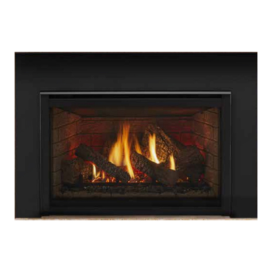
Model:
QVI-30FB
READ THIS MANUAL BEFORE INSTALLING OR
OPERATING THIS APPLIANCE. THIS INSTALLERS
GUIDE MUST BE LEFT WITH APPLIANCE FOR
FUTURE REFERENCE.
WARNING: IF THE INFORMATION
IN THESE INSTRUCTIONS IS NOT
FOLLOWED EXACTLY, A FIRE OR
EXPLOSION MAY RESULT CAUS-
ING PROPERTY DAMAGE, PER-
SONAL INJURY, OR DEATH.
- Do not store or use gasoline or other flam-
mable vapors and liquids in the vicinity of this
or any other appliance.
-
What to do if you smell gas
• Do not try to light any appliance.
• Do not touch any electrical switch.
• Do not use any phone in your building.
• Immediately call your gas supplier from a
neighbor's phone. Follow the gas supplier's
instructions.
• If you cannot reach your gas supplier, call
the fire department.
- Installation and service must be performed by a
qualified installer, service agency, or the gas
supplier.
Printed in U.S.A. Copyright 2007
Quadra-Fire, a brand of Hearth & Home Technologies
1445 North Highway, Colville, WA 99114
This product may be covered by one or more of the following patents: (United States) 4593510, 4686807, 4766876, 4793322, 4811534, 5000162, 5016609, 5076254, 5113843, 5191877, 5218953, 5263471,
5328356, 5341794, 5347983, 5429495, 5452708, 5542407, 5601073, 5613487, 5647340, 5688568, 5762062, 5775408, 5890485, 5931661, 5941237, 5947112, 5996575, 6006743, 6019099, 6048195, 6053165,
6145502, 6170481, 6237588, 6296474, 6374822, 6413079, 6439226, 6484712, 6543698, 6550687, 6601579, 6672860, 6688302B2, 6715724B2, 6729551, 6736133, 6748940, 6748942, 6769426, 6774802,
6796302, 6840261, 6848441, 6863064, 6866205, 6869278, 6875012, 6880275, 6908039, 6919884, D320652, D445174, D462436; (Canada) 1297749, 2195264, 2225408, 2313972; (Australia) 780250,
780403, 1418504 or other U.S. and foreign patents pending.
Quadra-Fire • QVI-30FB • 2020-900 Rev. H • 9/07
Owner's Manual
Installation and Operation
WARNING: IMPROPER INSTALLA-
TION, ADJUSTMENT, ALTERATION,
SERVICE OR MAINTENANCE CAN
CAUSE INJURY OR PROPERTY DAM-
AGE. REFER TO THIS MANUAL. FOR
ASSISTANCE OR ADDITIONAL INFOR-
MATION CONSULT A QUALIFIED IN-
STALLER, SERVICE AGENCY, OR THE
GAS SUPPLIER.
1. This appliance may be installed in an af-
termarket, permanently located, manufac-
tured (mobile) home, where not prohibited
by local codes.
2. This appliance is only for use with the type
of gas indicated on the rating plate. This
appliance is not convertible for use with
other gases, unless a certified kit is used.
In the Commonwealth of Massachusetts:
• installation must be performed by a licensed
plumber or gas fitter;
See Table of Contents for location of additional
Commonwealth of Massachusetts requirements.
Please contact your Quadra-Fire dealer with
any questions or concerns. For the location
of your nearest Quadra-Fire dealer, please
visit www.quadrafire.com.
1
Advertisement
Table of Contents
Troubleshooting

Related Manuals for Quadra-Fire QVI-30FB


Summary of Contents for Quadra-Fire QVI-30FB
- Page 1 6145502, 6170481, 6237588, 6296474, 6374822, 6413079, 6439226, 6484712, 6543698, 6550687, 6601579, 6672860, 6688302B2, 6715724B2, 6729551, 6736133, 6748940, 6748942, 6769426, 6774802, 6796302, 6840261, 6848441, 6863064, 6866205, 6869278, 6875012, 6880275, 6908039, 6919884, D320652, D445174, D462436; (Canada) 1297749, 2195264, 2225408, 2313972; (Australia) 780250, 780403, 1418504 or other U.S. and foreign patents pending. Quadra-Fire • QVI-30FB • 2020-900 Rev. H • 9/07...
-
Page 2: Safety And Warning Information
DO NOT place furniture or any other combustible Young children should be CAREFULLY SUPERVISED household objects within 36 inches of the fireplace when they are in the same room as the appliance. front. Quadra-Fire • QVI-30FB • 2020-900 Rev. H • 9/07... -
Page 3: Table Of Contents
Step 10 Lighting the Appliance ..........21 After the Installation ..............21 Section 4: Maintaining and Servicing Your Appliance ..22 Section 5: Troubleshooting ............ 23 Limited Lifetime Warranty ............25 = Contains updated information. Quadra-Fire • QVI-30FB • 2020-900 Rev. H • 9/07... -
Page 4: Service Parts Lists
Service Parts QVI-30FB Service Parts Diagram Log Set Assembly Part number list on following page. Quadra-Fire • QVI-30FB • 2020-900 Rev. H • 9/07... - Page 5 Patch Kit Conversion Kit NG NGK-QVI30FB Conversion Kit LP LPK-QVI30FB Pilot Orifice NG 446-505 Pilot Orifice LP 446-517 Regulator NG 060-518 Regulator LP 060-519 Additional service part numbers appear on following page. Quadra-Fire • QVI-30FB • 2020-900 Rev. H • 9/07...
-
Page 6: Service Parts
Flame Control Knob 571-531 Valve Bracket 773-145 Pilot Assembly NG 485-510A Pilot Assembly LP 485-511A Orifice NG (#31A) 506-800 Orifice LP (#49A) 065-801 Bracket, Orifice 778-169 Bracket, Pilot 783-170 Flexible Gas Connector 477-301A Quadra-Fire • QVI-30FB • 2020-900 Rev. H • 9/07... -
Page 7: Section 1: Approvals And Codes
National Electric Code ANSI/NFPA No. 70 (in the United States), or to the CSA C22.1 Canadian Electric Code (in Canada). These models may be installed in a bedroom or bed-sitting room in the U.S.A. and Canada. Quadra-Fire • QVI-30FB • 2020-900 Rev. H • 9/07... -
Page 8: Requirements For The Commonwealth Of Massachusetts
See Gas Connection section for additional Common- in print size no less than one-half (1/2) inch in size, “GAS wealth of Massachusetts requirements. VENT DIRECTLY BELOW. KEEP CLEAR OF ALL OB- STRUCTIONS”. Quadra-Fire • QVI-30FB • 2020-900 Rev. H • 9/07... -
Page 9: Section 2: Getting Started
The original fireplace may never be returned to solid fuel in this condition. Quadra-Fire • QVI-30FB • 2020-900 Rev. H • 9/07... - Page 10 * NOTE: If exhaust collar on insert and fireplace damper do not line up, add 4 inches (102mm) to minimum fireplace height for bends in vent pipe. Figure 1. Diagram of insert and minimum fireplace dimensions Quadra-Fire • QVI-30FB • 2020-900 Rev. H • 9/07...
- Page 11 2-13/16 1-1/16 GAS INLET ELECTRICAL 1-9/16 6-5/8 3-9/16 ACCESS (IF EQUIPPED) QVI-30FB MODEL DIMENSIONS Location Inches Millimeters 6-1/2 29-3/8 746.1 26-1/16 20-5/8 14-5/8 22-1/8 21-1/4 Figure 2. Diagram and model dimensions Quadra-Fire • QVI-30FB • 2020-900 Rev. H • 9/07...
-
Page 12: Section 3: Installing The Insert
50 feet. These dimensions are measured from the starting collars of the unit to the end of the last section of vent pipe. See dimension V in Figure 4. Quadra-Fire • QVI-30FB • 2020-900 Rev. H • 9/07... - Page 13 14/12 to 16/12 building. over 16/12 to 18/12 over 18/12 to 20/12 over 20/12 to 21/12 Figure 3. Minimum Height from Roof to Lowest Discharge Opening Quadra-Fire • QVI-30FB • 2020-900 Rev. H • 9/07...
- Page 14 INLET AIR COLLAR OF THE TERMINATION CAP OR TERMINATED IN THE CHIMNEY. A 3 FOOT SECTION OF STAINLESS STEEL FLEXIBLE LINER MUST BE ATTACHED DIRECTLY TO THE EXHAUST COLLAR ON COLLAR SLIDE PLATE. Quadra-Fire • QVI-30FB • 2020-900 Rev. H • 9/07...
- Page 15 (For Flashing Class-A Pipe) SLIDING PLATE CLASS A WOOD PIPE INLET AIR VENT PIPE 3 INCH STAINLESS STEEL COLLAR ADAPTER FOR EXHAUST (MUST BE INSTALLED) Figure 5. Typical configuration of vent liners. Quadra-Fire • QVI-30FB • 2020-900 Rev. H • 9/07...
-
Page 16: Step 2 Positioning, Leveling, And Securing The Insert
WARNING: 110-120 VAC MUST NEVER BE CONNECTED TO A CONTROL VALVE IN A MILLIVOLT SYSTEM. STANDING PILOT FLEXIBLE CONTROLS SHUT-OFF GAS LINE Figure 6. Gas Controls System Figure 7. Gas Supply Line Quadra-Fire • QVI-30FB • 2020-900 Rev. H • 9/07... -
Page 17: Step 5 Gas Pressure Requirements
(see Step 2. Positioning, Leveling and securing the Insert). THERMOCOUPLE THERMOPILE ROCKER SWITCH RED T1 VALVE WHITE T2 OPTIONAL WALL SWITCH THERMOSTAT OR REMOTE Figure 8. Standing Pilot Ignition Wiring Diagram Quadra-Fire • QVI-30FB • 2020-900 Rev. H • 9/07... - Page 18 TEMPERATURE SENSOR SWITCH PLACED, IT MUST BE REPLACED WITH TYPE C RATED WIRE. SPEED CONTROL (RHEOSTAT) GROUND WIRE (ATTACH TO ANY BEND UP METAL SURFACE) Figure 10. Fan Wiring Diagram TABS Quadra-Fire • QVI-30FB • 2020-900 Rev. H • 9/07...
-
Page 19: Step 7 Installing Logs And Ember Material
ON/OFF and insert the ON/OFF switch SWITCH through the hole at the upper right corner of the surround - it SURROUND will be retained in the hole. WITH TRIM Figure 14. Quadra-Fire • QVI-30FB • 2020-900 Rev. H • 9/07... -
Page 20: Step 9 Before Lighting The Appliance
Figure 15 Figure 15 shows the minimum vertical and corresponding maximum horizontal dimensions of mantels or other com- bustible projections above the gas fireplace. Quadra-Fire • QVI-30FB • 2020-900 Rev. H • 9/07... -
Page 21: Step 10 Lighting The Appliance
This will help avoid setting off smoke detectors, and help eliminate LEAVE THIS INSTALLATION MANUAL WITH THE any odors associated with the fireplace’s initial burning. APPLIANCE FOR FUTURE REFERENCE. Quadra-Fire • QVI-30FB • 2020-900 Rev. H • 9/07... -
Page 22: Section 4: Maintaining And Servicing Your Appliance
NOTE: DO NOT handle or attempt to clean the door when it is hot and DO NOT use abrasive cleaners. Quadra-Fire • QVI-30FB • 2020-900 Rev. H • 9/07... -
Page 23: Section 5: Troubleshooting
Check the burner orifice for stoppage. Remove stoppage. orifice. e. Wall switch or Follow the corrective action in Symptom and Possible Cause 1.a above. Check wires are defective. the switch and wiring. Replace where defective. Quadra-Fire • QVI-30FB • 2020-900 Rev. H • 9/07... -
Page 24: Troubleshooting
Ensure that no debris has been placed at the base of, or in the area of the air holes in the center of the base pan beneath the burner. Ensure that the glass is tightened properly on the unit, particularly on top corners. Quadra-Fire • QVI-30FB • 2020-900 Rev. H • 9/07... -
Page 25: Limited Lifetime Warranty
This limited Lifetime Warranty is effective on all appliances sold after May 1, 2002 and supersedes any and all warranties currently in existence. 250-8620J 12/05 Quadra-Fire • QVI-30FB • 2020-900 Rev. H • 9/07...
Need help?
Do you have a question about the QVI-30FB and is the answer not in the manual?
Questions and answers