Quadra-Fire QFI30FB Owner's Manual
Hide thumbs
Also See for QFI30FB:
- Installation instructions (3 pages) ,
- Installation instructions (5 pages)
Table of Contents
Advertisement
Quick Links
Models:
QFI30FB
QFI35FB
• Important operating
a n d m a i n t e n a n c e
instructions included.
WARNING: If the information in these
instructions is not followed exactly, a fi re
or explosion may result causing property
damage, personal injury, or death.
• DO NOT store or use gasoline or other fl am-
mable vapors and liquids in the vicinity of this
or any other appliance.
• What to do if you smell gas
- DO NOT try to light any appliance.
- DO NOT touch any electrical switch. DO
NOT use any phone in your building.
- Immediately call your gas supplier from a
neighbor's phone. Follow the gas suppli-
er's instructions.
- If you cannot reach your gas supplier, call
the fi re department.
• Installation and service must be performed
by a qualifi ed installer, service agency, or the
gas supplier.
This appliance may be installed as an OEM installation in
manufactured home (USA only) or mobile home and must be
installed in accordance with the manufacturer's instructions
and the manufactured home construction and safety standard,
Title 24 CFR, Part 3280 or Standard for Installation in Mobile
Homes, CAN/CSA Z240MH, in Canada.
This appliance is only for use with the type(s) of gas indicated
on the rating plate.
R
NOTICE
DO NOT DISCARD THIS MANUAL
• Read, understand and follow
these instructions for safe
installation and operation.
Quadra-Fire • QFI30FB, QFI35FB • 2221-900 Rev. K • 3/11
Owner's Manual
• Leave this manual with
party responsible for use
and operation.
WARNING
HOT SURFACES!
Glass and other surfaces are hot during
operation AND cool down.
Hot glass will cause burns.
• DO NOT touch glass until it is cooled
• NEVER allow children to touch glass
• Keep children away
• CAREFULLY SUPERVISE children in same room as
fi replace.
• Alert children and adults to hazards of high temperatures.
High temperatures may ignite clothing or other fl ammable
materials.
• Keep clothing, furniture, draperies and other fl ammable
materials away.
This appliance has been supplied with an integral barrier
to prevent direct contact with the fi xed glass panel. DO
NOT operate the appliance with the barrier removed.
Contact your dealer or Hearth & Home Technologies if the
barrier is not present or help is needed to properly install one.
In the Commonwealth of Massachusetts installation must be
performed by a licensed plumber or gas fi tter.
A CO detector shall be installed in the room where the appliance
in installed.
Installation and service of this appliance should be
performed by qualifi ed personnel. Hearth & Home
Technologies suggests NFI certifi ed or factory trained
professionals, or technicians supervised by an NFI
certifi ed professional.
Installation and Operation
1
Advertisement
Table of Contents

Related Manuals for Quadra-Fire QFI30FB


Summary of Contents for Quadra-Fire QFI30FB
- Page 1 Technologies suggests NFI certifi ed or factory trained This appliance is only for use with the type(s) of gas indicated professionals, or technicians supervised by an NFI on the rating plate. certifi ed professional. Quadra-Fire • QFI30FB, QFI35FB • 2221-900 Rev. K • 3/11...
-
Page 2: Congratulations
Your new Quadra-Fire gas fi replace will give you years of As the owner of a new fi replace, you’ll want to read and durable use and trouble-free enjoyment. Welcome to the carefully follow all of the instructions contained in this Owner’s... -
Page 3: Table Of Contents
B. Flue Damper........21 Quadra-Fire • QFI30FB, QFI35FB • 2221-900 Rev. K • 3/11... -
Page 4: Limited Lifetime Warranty
Limited 3 years Firebox and heat exchanger Lifetime All replacement parts 90 Days beyond warranty period See conditions, exclusions, and limitations on next page. 4021-645C 12-29-10 Page 1 of 2 Quadra-Fire • QFI30FB, QFI35FB • 2221-900 Rev. K • 3/11... - Page 5 B. Limited Lifetime Warranty (continued) WARRANTY CONDITIONS: WARRANTY EXCLUSIONS: This warranty is void if: LIMITATIONS OF LIABILITY: 4021-645C 12-29-10 Page 2 of 2 Quadra-Fire • QFI30FB, QFI35FB • 2221-900 Rev. K • 3/11...
-
Page 6: Listing And Code Approvals
(0-2000 FT) QFI30-FB (LP) CANADA 31,000 15,500 (2000-4500 FT) 40,000 20,000 (0-2000 FT) QFI35-FB (NG) CANADA 37,000 19,250 (2000-4500 FT) 38,000 19,000 (0-2000 FT) QFI35-FB (LP) CANADA 35,000 17,000 (2000-4500 FT) Quadra-Fire • QFI30FB, QFI35FB • 2221-900 Rev. K • 3/11... -
Page 7: User Guide
DECORATIVE DOORS (NOT SHOWN) SECTION 2.D. FIXED GLASS ASSEMBLY (NOT SHOWN) SECTION 12.I. CLEAR SPACE SECTION 2.C. MANTEL SECTION 5.B. HEARTH BATTERY BACKUP ACCESS SECTION 2.G. Figure 2.1 General Operating Parts Quadra-Fire • QFI30FB, QFI35FB • 2221-900 Rev. K • 3/11... -
Page 8: Clear Space
Contact your dealer or Hearth & Home Technologies if the barrier is not present or help is needed to properly install one. For more information refer to the instructions supplied with your decorative door or front. Quadra-Fire • QFI30FB, QFI35FB • 2221-900 Rev. K • 3/11... -
Page 9: Ipi Battery Tray/Battery Installation
Figure 2.4 Pull Left Side of Tray Out and Disengage Notch SELECTOR SWITCH STATUS INDICATOR LED FLAME HI/LO SWITCH NG/LP SETTING Figure 2.6 Control Module Figure 2.5 Battery Tray Pulled Out Quadra-Fire • QFI30FB, QFI35FB • 2221-900 Rev. K • 3/11... -
Page 10: Before Lighting Fireplace
fi ve minute time period. Gas may accumulate in fi rebox. Call a quali- fi ed service technician. MODULE RESET SWITCH Figure 2.7. Module Reset Switch Quadra-Fire • QFI30FB, QFI35FB • 2221-900 Rev. K • 3/11... -
Page 11: Lighting Instructions (Ipi)
See installation and operating instructions accompanying appliance. For additional information on operating your Hearth & Home Technologies fi replace, please refer to www.fi replaces.com. Final inspection by Quadra-Fire • QFI30FB, QFI35FB • 2221-900 Rev. K • 3/11... -
Page 12: After Appliance Is Lit
In an intermittent pilot ignition system (IPI), the pilot fl ame should turn off when appliance is Is it normal to see the pilot fl ame burn turned off. Some optional control systems available with IPI models may allow pilot fl ame to continually? remain lit. Quadra-Fire • QFI30FB, QFI35FB • 2221-900 Rev. K • 3/11... -
Page 13: Maintenance And Service
• Carefully set fi xed glass assembly in place on appliance. Hold glass in place with one hand and secure glass latches with the other hand. • Reinstall door or decorative front. Quadra-Fire • QFI30FB, QFI35FB • 2221-900 Rev. K • 3/11... -
Page 14: Maintenance Tasks-Service Technician
• Remove the logs, grate, and burner. • Remove the two ember glass retainer tabs. • Remove the ember glass. • Replace light bulb. • Reassemble components in reverse order of disassembly. Quadra-Fire • QFI30FB, QFI35FB • 2221-900 Rev. K • 3/11... - Page 15 Clean with emery cloth or replace as required. • Verify that there is not a short in fl ame sense circuit by checking continuity between pilot hood and fl ame sense rod. Replace pilot as necessary. Quadra-Fire • QFI30FB, QFI35FB • 2221-900 Rev. K • 3/11...
-
Page 16: Getting Started
SECTION 5.B AND 11.A SURROUND OR FRONT NOT SHOWN SECTION 2.D AND SECTION 8. HEARTH EXTENSION GAS LINE (SECTION 9) ACCESS THROUGH EXISTING MASONRY OR WOODBURNING FIREPLACE Figure 4.1 Typical System Quadra-Fire • QFI30FB, QFI35FB • 2221-900 Rev. K • 3/11... -
Page 17: Design And Installation Considerations
Hammer Noncorrosive leak check solution 1/2 - 3/4 inch length, #6 or #8 Self-drilling screws Caulking material (300ºF minimum continuous exposure rating) Stove cement (1200ºF or higher continuous exposure rating) Quadra-Fire • QFI30FB, QFI35FB • 2221-900 Rev. K • 3/11... -
Page 18: Fireplace Size Requirements
**Unit depth is measured to the back of the surround to give the depth needed for installation. In addition to these dimensions, also reference Clearances and Mantel Projections (Section 5.B). Figure 5.1 Fireplace Opening Quadra-Fire • QFI30FB, QFI35FB • 2221-900 Rev. K • 3/11... -
Page 19: Mantel And Wall Projections
fi rebox. Combustible facings must not extend behind the insert surround. For non-combustible material specifi cations refer to section 1.E. Figure 5.2 Mantel Clearance Quadra-Fire • QFI30FB, QFI35FB • 2221-900 Rev. K • 3/11... -
Page 20: Termination Locations
Over 16/12 to 18/12 ..........7.0 Over 18/12 to 20/12 ..........7.5 Over 20/12 to 21/12 ..........8.0 * 3 foot minimum in snow regions Figure 6.1 Minimum Height From Roof To Lowest Discharge Opening Quadra-Fire • QFI30FB, QFI35FB • 2221-900 Rev. K • 3/11... -
Page 21: Installation Preparation
• Install gas line into fi rebox cavity. • Check local codes and gas line sizing requirements following NFPA51. See Section 9. Quadra-Fire • QFI30FB, QFI35FB • 2221-900 Rev. K • 3/11... -
Page 22: Installing Vent Pipe And Appliance
VENT PIPE NOTE: TO ACHIEVE OPTIMUM PERFOR- INLET AIR STARTING COLLAR MANCE OF INSERT, MINIMIZE OR AVOID BENDS IN EXHAUST VENT PIPE. STARTING COLLAR BRACKET EXHAUST STARTING COLLAR Figure 8.1 Quadra-Fire • QFI30FB, QFI35FB • 2221-900 Rev. K • 3/11... -
Page 23: Connecting Vent Pipe
fl ue tile top. and either the termination cap inlet air collar OR terminate within chimney. • DO NOT allow vent to sag below connection point to appliance. Quadra-Fire • QFI30FB, QFI35FB • 2221-900 Rev. K • 3/11... -
Page 24: Installing Adaptor And Termination Cap
Remove 18 inch x 18 inch fl ashing on cap by removing 3 VENT PIPE VENT PIPE screws. Connect both the LINK-ZC-ADPB to Class A Pipe and the termination cap to the LINK-ZC-ADPB with the self tapping screws provided. Figure 8.5 Quadra-Fire • QFI30FB, QFI35FB • 2221-900 Rev. K • 3/11... -
Page 25: Gas Information
2000 feet and 4500 feet. Above 4500 feet, (13 mm) control valve inlet. consult local gas utility. • If substituting for these components, please consult local codes for compliance. Quadra-Fire • QFI30FB, QFI35FB • 2221-900 Rev. K • 3/11... -
Page 26: Electrical Information
BATTERY PACK 6V DC (AA X 4) BLACK LIGHT WIRE ASSEMBLY ORANGE GREEN (2201-013) (PILOT) (MAIN) EMBER BULB 20W (2) (2088-136) ACCENT SOCKETS (2) GROUND (2146-402) Figure 10.1 IPI Wiring Diagram Quadra-Fire • QFI30FB, QFI35FB • 2221-900 Rev. K • 3/11... -
Page 27: Ipi Battery Tray/Battery Installation
(fan blades). BROWN BLACK PLUG INTO 120V EXISTING OUTLET GROUND (TO VALVE BRACKET) GREEN (TO VALVE) ORANGE (TO VALVE) DC REGULATOR RECEPTACLE BLOWERS BLOWER RECEPTACLE Figure 10.2 Fan Wiring Diagram Quadra-Fire • QFI30FB, QFI35FB • 2221-900 Rev. K • 3/11... -
Page 28: Finishing
Combustible facings must not extend behind the insert surround. For non-combustible material specifi cations refer to section 1.E. EXISTING NON-COMBUSTIBLE FACING 12 IN. MAX. 12 IN. MIN. Figure 11.1 Mantel Clearance Quadra-Fire • QFI30FB, QFI35FB • 2221-900 Rev. K • 3/11... -
Page 29: Appliance Setup
WARNING! Risk of Fire and Electric Shock! Use ONLY Hearth & Home Technologies-approved optional acces- sories with this appliance. Using non-listed accessories could result in a safety hazard and will void the warranty. Quadra-Fire • QFI30FB, QFI35FB • 2221-900 Rev. K • 3/11... -
Page 30: Ember Placement
The embers provided should be enough for 3 to 5 applications. EMBERS NOT ALLOWED IN PILOT AREA Figure 12.2 Placement of Embers-QFI30FB EMBERS NOT ALLOWED IN PILOT AREA Figure 12.3 Placement of Embers-QFI35FB Quadra-Fire • QFI30FB, QFI35FB • 2221-900 Rev. K • 3/11... -
Page 31: Install The Log Assembly
Log #2 (SRV2221-701): Position Log #2 as shown in Figure 5. See Figure 2 and Figure 6 for additional points of reference. The recessed area on the bottom of the log and the back right corner of the burner top mate. Quadra-Fire • QFI30FB, QFI35FB • 2221-900 Rev. K • 3/11... - Page 32 Log #5 on the fl at spot indicated in Figure 7. Mate the slot, located on the bottom of the log, with the left log pin. Ensure the nose of the log does not cover any burner ports. Quadra-Fire • QFI30FB, QFI35FB • 2221-900 Rev. K • 3/11...
- Page 33 Log #7 on the fl at spot indicated in Figure 11. Place the back end of Log #7 on the left side of the knot. See Figure 14. 2221-935B Quadra-Fire • QFI30FB, QFI35FB • 2221-900 Rev. K • 3/11...
- Page 34 Slide the log back until it rest against the back of the log support. The left end of the log should touch Log #1. Swing the right end of the log counterclockwise until it contacts the right refractory wall. Quadra-Fire • QFI30FB, QFI35FB • 2221-900 Rev. K • 3/11...
- Page 35 Log #6 (SRV2223-705): Position Log #6 as shown in Figure 11. See Figures 2, 5 and 10 for additional reference points. Place the front and back ends of the log on the fl at spots as shown in Figure 11. Quadra-Fire • QFI30FB, QFI35FB • 2221-900 Rev. K • 3/11...
- Page 36 Log #7 (SRV2221-707): Position Log #7 as shown in Figure 12. See Figure 2 and 10 for additional reference points. Place the front and back ends of the log on the fl at spots as shown in Figure 12. 2223-935B Quadra-Fire • QFI30FB, QFI35FB • 2221-900 Rev. K • 3/11...
-
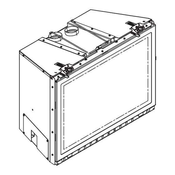
Page 37: Fixed Glass Assembly
Note that the extended glass latch tabs on the glass frame are for the bottom glass latches. QFI30FB 1/4 in. Full Open QFI35FB 1/4 in. Full Open LATCHES (BOTH BOTTOM AND TOP) GLASS ASSEMBLY Figure 12.2 Fixed Glass Assembly Quadra-Fire • QFI30FB, QFI35FB • 2221-900 Rev. K • 3/11... -
Page 38: Troubleshooting
D. Pilot valve solenoid Verify that 1.5 to 1.8 VDC is supplied to pilot solenoid from module. If below 1.5 volts, replace module. If 1.5 volts or greater, replace valve. Quadra-Fire • QFI30FB, QFI35FB • 2221-900 Rev. K • 3/11... - Page 39 fl ame sensing rod. Verify continuity with a multi-meter with ohms set at lowest range. Replace pilot if any damage is detected. Quadra-Fire • QFI30FB, QFI35FB • 2221-900 Rev. K • 3/11...
-
Page 40: Reference Materials
4-1/2 4-3/16 1-9/16 1-9/16 13-3/8 12-1/8 *Note: Location G on Figure 14.1 is measuring the appliance depth, for installation depth reference Location G on Figure 5.1. Figure 14.1 Appliance Dimensions Quadra-Fire • QFI30FB, QFI35FB • 2221-900 Rev. K • 3/11... -
Page 41: Vent Kits Components
GK to connect collinear fl ex vent to SL-D vent pipe to extend the run. FLEX3-30: One 3 inch fl exible liner expands to 30 feet. FLEX-CNCT: Connector kit - 3 inch liner to 3 inch liner, one connector per kit. Quadra-Fire • QFI30FB, QFI35FB • 2221-900 Rev. K • 3/11... -
Page 42: Service Parts
2201-112 Grate Assembly 2221-016 Glass Door Assembly GLA-2201 Power Cord Assembly 2201-017 Cover Plate, Right 2202-114 Blower Assembly GFK-210 Cover Plate, Back 2202-104 Additional service part numbers on following page. Quadra-Fire • QFI30FB, QFI35FB • 2221-900 Rev. K • 3/11... - Page 43 2202-112 Log Grate 2223-016 Glass Door Assembly GLA-2202 Power Cord Assembly 2201-017 Cover Plate, Right 2202-114 Blower Assembly GFK-210 Cover Plate, Back 2202-104 Additional service part numbers on following page. Quadra-Fire • QFI30FB, QFI35FB • 2221-900 Rev. K • 3/11...
- Page 44 Pilot Bracket 2201-118 19.16 Ember Glass 2201-115 **Fuse for battery pack can be sourced locally, not a warranty item. Specs are 500mA~10A 3/4” long Additional service part numbers on following page. Quadra-Fire • QFI30FB, QFI35FB • 2221-900 Rev. K • 3/11...
- Page 45 Regulator LP LPK-DXV-50 QFI35FB Converion Kits Conversion Kit NG NGK-I35FB Conversion Kit LP LPK-I35FB Pilot Orifi ce NG 2098-520 Pilot Orifi ce LP 2098-512 Regulator NG NGK-DXV-50 Regulator LP LPK-DXV-50 Quadra-Fire • QFI30FB, QFI35FB • 2221-900 Rev. K • 3/11...
-
Page 46: Contact Information
5647340, 5890485, 5941237, 5947112, 5996575, 6006743, 6019099, 6053165, 6145502, 6170481, 6374822, 6484712, 6601579, 6769426, 6863064, 7077122, 7098269, 7258116, 7470729 or other U.S. and foreign patents pending. 2000-945 Printed in U.S.A. - Copyright 2011 Quadra-Fire • QFI30FB, QFI35FB • 2221-900 Rev. K • 3/11...
Need help?
Do you have a question about the QFI30FB and is the answer not in the manual?
Questions and answers