Table of Contents
Advertisement
Advertisement
Table of Contents

Subscribe to Our Youtube Channel
Related Manuals for Notifier Fire Alarm Control Panel


Summary of Contents for Notifier Fire Alarm Control Panel
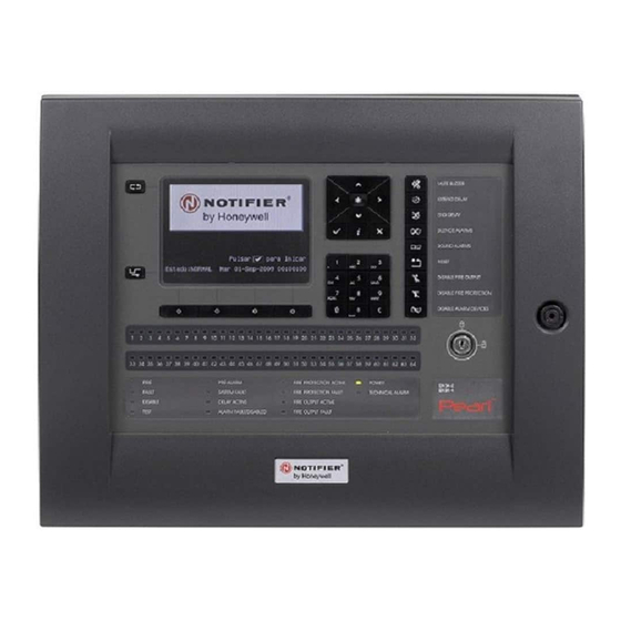
- Page 1 Pearl™ Fire Alarm Control Panel Operating Manual 997-670-000-2...
-
Page 2: Table Of Contents
Contents Contents 4.2 Keyswitch Entry ............ 4-1 5 Navigating the Panel Menus ......5-1 1 Pearl™ 2-Loop Fire Control Panel ........ 5.1 Disable/Enable Menu ..........5-2 1.1 Introduction ............1-1 5.1.1 Zones and Devices ..........5-2 1.2 User Interface ............1-1 5.1.1.1... - Page 3 Contents 5.5 Commissioning Menus ........5-19 997-670-000-2 Operating Manual www.notifierknowledge.com Contents - ii...
-
Page 4: Pearl™ 2-Loop Fire Control Panel
Helpful descriptions and tips are also provided within this document to assist the user in understanding the status information provided by the Pearl™ panel’s LCD and LED indicators. The Pearl™ Fire Alarm Control Panel has been designed to meet the requirements of EN54-2. 1.2 User Interface The Pearl™... - Page 5 Panel User Interface Context-sensitive Help Button. When responding to a change in system status or when navigating the panel’s various menus, press the context-sensitive information button ( ) at any time for guidance and helpful tips. LEDs. System status LEDs are also provided and these are located below the four user function keys below the LCD.
-
Page 6: Lcd Primary Status Indicator
Panel User Interface 1.2.1 LCD Primary Status Indicator The LCD is the panel’s primary status indicator. This allows all event information, required to be displayed to meet the requirements of EN54-2 for any system condition or detected event, to be displayed on the LCD and in a clear and concise way. - Page 7 Panel User Interface FAULT EVENT Fault summary information area, which includes: If the panel detects a fault, the Status Normal screen on the LCD is replaced by a fault summary screen, the buzzer sounds in steady Total individual faults, detection zones in fault and wiring loops in fault. mode, the FAULT LED pulses and the MUTE BUZZER function key flashes.
-
Page 8: Function Keys
Panel User Interface 1.2.2 Function Keys Panel operation, at user access Levels 1 and 2, is controlled by the various function keys located on the front fascia. The group of keys to the right of the LCD provide the following user functions: 1. -
Page 9: Led Status Indicators
Panel User Interface 1.2.3 LED Status Indicators In addition to details of detected events being displayed on the LCD, a number of LED status indicators are provided in the lower area of the panel fascia. The upper two banks of LEDs are zone fire LEDs (zones 1 to 64) and may not be fitted. -
Page 10: Fire & Fault Events - What To Do
Fire and Fault Events - What to do Fire & Fault Events - What to do 2.1 Fire Event If the panel enters the alarm state, i.e. a Fire condition has been detected, the following visual and audible indications are given: - The LCD displays information about the fire event, such as first and latest zone and first device in alarm. A Fire Tab is displayed at the bottom left-hand corner of the LCD. -
Page 11: Day Mode Operation
Fire and Fault Events - What to do 2.1.3 Day Mode Operation If a Day Mode program has been configured and is currently active (the DAY MODE LED is lit), the sensitivity of sensors will be changed automatically as configured when the panel was commissioned. In most cases the sensitivity of sensors is reduced to avoid the incidence of false alarms when the building is occupied. In the event a real fire condition is detected the panel responds in the normal way but after a short alarm condition verification period. At the end of this verification period activation of the required outputs, such as... -
Page 12: Fault Event
Fire and Fault Events - What to do 2.2 Fault Event If the panel enters a fault state, i.e. a fault condition has been detected, the following visual and audible indications are given: - The LCD displays information about the fault event, such as panel condition or zone and device information. -
Page 13: Reset Key
Fire and Fault Events - What to do 2.3 RESET Key The RESET key is used to clear all fire and fault status indications on the panel and return it to its normal condition. Non- quiescent Note: The RESET key must not be used to clear fire or fault Condition indications without the appropriate actions having been taken to investigate and remedy the cause of any such events. -
Page 14: Panel Status & User Level 1 Functions
Panel Status & User Level 1 Functions Panel Status & User Level 1 Functions 3.1 Status Normal The following control keys function at user access Level 1: - MUTE BUZZER - CHANGE TABS With the panel at user access Level 1 and also in the quiescent state, i.e. -
Page 15: Enabling User Access (Level 2)
Enabling User Access (Level 2) Enabling User Access (Level 2) 4.1 Passcode Entry With the Status Normal screen displayed on the LCD, pressing the key will present the user access level passcode request entry screen. Entry of a valid passcode enables the user to access the appropriate panel menus. -
Page 16: Navigating The Panel Menus
Navigating the Panel Menus Navigating the Panel Menus Once access to the user access Level 2 menus is obtained (see Section 4 Enabling User Access (Level 2), selection of menu options is very simple to do. With a menu option highlighted press the key to select. -
Page 17: Disable/Enable Menu
Navigating the Panel Menus 5.1 Disable/ Enable Menu The Disable/Enable function is available from the user access Level 2 Main Menu. Enter the user access Level 2 passcode or insert the key and turn clockwise through 90° to display the Main Menu. The MENU tab is also displayed once the Main Menu is accessed. -
Page 18: To Disable A Zone Or Device
Navigating the Panel Menus 5.1.1.1 To Disable a Zone or Device This description is for a panel working in stand-alone mode. Performing disablements over a network is described after this. Use the navigation buttons to highlight the zone to be disabled/enabled and then press the key to change its state. - Page 19 Navigating the Panel Menus Working Example - Disable Zone 3 With the Main Menu displayed on the LCD, press the numeric key ‘1’ to select the ‘Disable/Enable’ option. Press the ‘1’ key on the numeric keypad to select ‘Zones and Devices’. The list of all configured zones is displayed, the first zone in the list is highlighted.
-
Page 20: Fault Relay Output
Navigating the Panel Menus 5.1.2 Fault Relay Output Select option 2: Fault Relay to enable/disable the fault relay output. To enable/disable the fault relay output press the key. Each time key is pressed the enable/disable state is changed. With the fault relay output in a disabled state, the DISABLE LED is lit. The DISABLE tab is displayed with disabled fault relay output. -
Page 21: Fault Routing Outputs
Navigating the Panel Menus 5.1.3 Fault Routing Outputs Select option 3: Fault Routing Outputs to enable/disable the fault routing output circuit(s). To enable/disable the fault routing output(s) press the key. Each time the key is pressed the enable/disable state changes (toggled). Press the key at any time to exit. -
Page 22: Time-Of-Day Manual Override
Navigating the Panel Menus 5.1.5 Time-of-Day Manual Override Select option 4: Time-of-Day Manual Override to manually override an active Time-of-Day program. This override function is only possible if a program (up to ten programs are configurable) was configured at system commissioning. If a Time-of-Day program is active the DAY MODE LED is lit. -
Page 23: Start/End Testing
Navigating the Panel Menus 5.2 Start/End Testing Various parts of the fire alarm system may be tested at user access Level 2, as well as performing a function test of the panel’s visual indicators and internal buzzer. When a zone walk test is in progress, the TEST LED lights. When a walk test is in progress the TEST tab is shown on the LCD display. -
Page 24: Testing Multiple Zones
Navigating the Panel Menus 5.2.1.1 Testing Multiple Zones More than one zone may be tested at the same time. Press the navigation buttons to highlight another zone in the list and then press the key to select for testing. If required, repeat this procedure for other zones to be tested. To view the status of the devices in any other zones in test use the / navigation buttons to move from one zone to another. -
Page 25: Auto High Test
Navigating the Panel Menus 5.2.2 Auto High Test This is a maintenance facility only and is only available using an access Level 3 passcode. 5.2.3 Alarm Devices Alarm devices, such as sounders or control modules (set as type SNDR, STRB but not as type CTRL), may be tested. Multiple devices may be tested at the same time. -
Page 26: Leds
Navigating the Panel Menus 5.2.4 LEDs To test all of the panel’s LEDs and function key backlights, select option 4: LEDs from the Test Menu. The panel’s LEDs are then lit (4 rapid flashes) individually in the following pre-defined sequence: The System Status LEDs. -
Page 27: Lcd
Navigating the Panel Menus 5.2.5 LCD Selection of option 5: LCD displays a test start screen as shown opposite. Pressing the key displays a grey screen - the grey screen is made up from every other pixel turned on, the pixels between are turned off. -
Page 28: Internal Buzzer
Navigating the Panel Menus 5.2.6 Internal Buzzer Select option 6: Buzzer from the Test Menu to test the panel’s internal buzzer. Press the ‘6’ key on the alphanumeric keypad or, if highlighted, press the key. When selected the buzzer is activated with a rapid-pulsing output pattern. -
Page 29: Setting Time/Date
Navigating the Panel Menus 5.3 Setting Time/Date To set or change the time and/or date, from the Main Menu select option 3: Set Clock. Press the ‘3’ key on the alphanumeric keypad to select the Set Clock function. Alternatively, use the navigation buttons to move the highlight to the desired option in the list and press the key. -
Page 30: View Status Menu
Navigating the Panel Menus 5.4 View Status Menu Various system-related data and event information can be displayed using these options. 5.4.1 Historic Log Each status change event registered by the panel, including those resulting from control key actions, such as mute buzzer, reset, etc. and fire and fault conditions are stored in a single historic event log. -
Page 31: Device Status
Navigating the Panel Menus 5.4.2 Device Status This option allows the type and status of any loop device to be viewed. Other information related to the device is also displayed but the type of data displayed depends upon the device protocol, as follows: CLIP loop protocol: the device type and its current state (analogue PW values) are displayed. - Page 32 Navigating the Panel Menus Note: Following the configuration of Opal devices as CLIP the device status screen shows the CLIP values as well as the Opal-related values for those devices. The CLIP values are displayed on the LCD; page down to view the Opal values. If a configured device is not found at the address entered, the LCD displays a screen typically as shown with no PW values (all shown as ‘000’).
-
Page 33: Alarm Count
Navigating the Panel Menus 5.4.3 Alarm Count Each time the panel enters the alarm state since the system was installed these events are logged, i.e. stored in memory for later retrieval by the service engineer. This menu option allows the alarm event total to be displayed on the LCD. - Page 34 Navigating the Panel Menus 5.5 Commissioning Menus Access to the commissioning menus requires the entry of an access Level 3 passcode. These functions are not described in this document. 997-670-000-2 Operating Manual www.notifierknowledge.com Section 5 - 19...
Need help?
Do you have a question about the Fire Alarm Control Panel and is the answer not in the manual?
Questions and answers