Notifier NFS-640 Installation Manual
Fire alarm control panel
Hide thumbs
Also See for NFS-640:
- Programming manual (116 pages) ,
- Manual (9 pages) ,
- Operation manual (88 pages)

Related Manuals for Notifier NFS-640


Summary of Contents for Notifier NFS-640
- Page 1 Fire Alarm Control Panel NFS-640 Installation Manual Document 51332 12/01/2003 Rev: P/N 51332:B1 ECN 03-419...
-
Page 2: Fire Alarm System Limitations
(especially in bedrooms), smoking in bed, and violent explosions (caused by escaping gas, improper storage of flammable materials, etc.). Precau-L-4-2003.fm NFS-640 Installation Manual P/N 51332:B1 12/01/2003... -
Page 3: Installation Precautions
Acclimate Plus™, AWACS™, HARSH™, NOTI•FIRE•NET™, ONYX™, and VeriFire™ are trademarks, and FlashScan®, UniNet®, and VIEW® are registered trademarks of NOTIFIER. NION™ is a trademark of NIS. NIS™ and Notifier Integrated Systems™ are trademarks and NOTIFIER® is a registered trademark of Fire•Lite Alarms, Inc. Echelon® is a registered trademark and LonWorks™ is a trademark of Echelon Corporation. ARCNET® is a registered trademark of Datapoint Corporation. - Page 4 Brief description of content you think should be improved or corrected • Your suggestion for how to correct/improve documentation Send email messages to: TechPubs@fla-whq.com Please note this email address is for documentation feedback only. If you have any technical issues, please contact Technical Services. NFS-640 Installation Manual P/N 51332:B1 12/01/2003...
-
Page 5: Table Of Contents
3.7.4 Installing the Panel Circuit Modules ...............44 3.7.5 Connecting ICM-4RK and ICE-4 Modules .............45 3.7.6 Field-Wiring the ICM-4RK and ICE-4 (NFPA Style Y or Z) .........46 3.7.7 Connecting CRM-4RK/CRE-4 Modules ..............47 3.8 Auxiliary Relay Module (ARM-4): Product-Specific Details ..........48 NFS-640 Installation Manual P/N 51332:B1 12/01/2003... - Page 6 D.1 Standalone Application ......................83 D.1.1 NFS-640 with KDM-2 ....................83 D.1.2 NFS-640 with NCA ....................83 D.2 Local Network Application ....................83 D.3 Automatic Alarm Signal Silence ..................83 D.4 Annunciator Applications ....................83 D.5 Releasing Devices ......................83 Index ..............................85 NFS-640 Installation Manual P/N 51332:B1 12/01/2003...
-
Page 7: Section 1 About This Manual
EIA-485 and EIA-232 Serial Interface Standards NEC Article 300 Wiring Methods NEC Article 760 Fire Protective Signaling Systems Applicable Local and State Building Codes Requirements of the Local Authority Having Jurisdiction C22.1-98 The Canadian Electrical Code, Part 1 NFS-640 Installation Manual P/N 51332:B1 12/01/2003... -
Page 8: Supplemental Documentation
Compatible Conventional Devices (Non-addressable) Document Number Device Compatibility Document 15378 Fire Alarm Control Panel (FACP) and Main Power Supply Installation Document Number NFS-640 Installation, Operations, and Programming Manuals 51332, 51334, 51333 Voice Alarm System Manual 51252 SLC Wiring Manual 51253... -
Page 9: Cautions And Warnings
CAUTION: Information about procedures that could cause programming errors, runtime errors, or equipment damage. WARNING: Indicates information about procedures that could cause irreversible damage to the control panel, irreversible loss of programming data or personal injury. NFS-640 Installation Manual P/N 51332:B1 12/01/2003... - Page 10 Notes NFS-640 Installation Manual P/N 51332:B1 12/01/2003...
-
Page 11: Section 2 System Overview
Section 2 System Overview 2.1 System Description The NFS-640(E) control panel is a modular, intelligent fire alarm control panel (FACP) with an extensive list of powerful features. The control panel integrates a central processing unit (CPU), a 6 amp power supply, and a battery charger. This is combined with a mounting chassis and cabinet to create a complete fire alarm control system. -
Page 12: Options
The capacity of the secondary power source (standby batteries). 2.2 System Components 2.2.1 Basic Equipment Required A basic NFS-640 system requires at least the following components: The control panel. CPU-640 (120V operation) or CPU-640E (240V operation). This printed circuit board is the “control panel” itself and the heart of the system. It also includes an expander cable for connecting panel modules, a grounding cable, battery interconnect cables, and document kit. -
Page 13: Control Panel Circuit Board
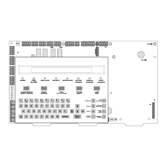
6 amp power supply with battery charger, a signaling line circuit (SLC) and the central processing unit. A keypad/display unit can be installed over the power supply as shown Figure 1. Figure 1 NFS-640 Control Panel with Optional Keypad/Display Unit Installed FIRE POWER... -
Page 14: Circuit Board Components
(SLC Loop #2) 10 Amp Slo-Blow Fuse J10 - Security Tamper Switch P/N 12067 J11 - Auxiliary Trouble Input TB1 - Battery Connection J5 - Panel Circuits (supervised) (over-current protected) J6 - Panel Circuits (supervised) NFS-640 Installation Manual P/N 51332:B1 12/01/2003... - Page 15 D54 - ‘AC ON’ / Power LED D75 - Fire Alarm LED D76 - Pre-Alarm LED D77 - Security LED D81 - Point Disabled LED D80 - Signals Silenced LED D79 - System Trouble LED D78 - Supervisory LED NFS-640 Installation Manual P/N 51332:B1 12/01/2003...
-
Page 16: System Cabinets
MP-1B is also used to mount panel circuit modules. Note: When using trim rings, mount backbox with at least 1 inch (2.54 cm) between wall surface and front of backbox, to allow door to open fully past the trim ring. NFS-640 Installation Manual P/N 51332:B1 12/01/2003... -
Page 17: Optional Devices
System Overview 2.4 Optional Devices Several optional components can be installed within the NFS-640 system. This list provides only a sample of common equipment; for a complete list of what is available, refer to Appendix C “Compatible Equipment” and for a list of conventional equipment, refer to the Device Compatibility Chart. -
Page 18: Intelligent Detectors
159 detectors. The sensitivity of each intelligent detector can be programmed (refer to Appendix C in the NFS-640 Programming Manual for details). Note: A blinking LED on an intelligent detector indicates communication between the detector and the control panel. -
Page 19: Addressable Modules
2.6 Addressable Modules Control Modules and Monitor Modules provide an interface between the control panel and conventional notification and initiating devices. Each module can be set to respond to an address NFS-640 Installation Manual P/N 51332:B1 12/01/2003... - Page 20 • XP6-R controls six Form-C relays. Applications are equivalent to those for XP5-C set as a Form-C relay. • XP10-M supervises ten Class-B addressable Initiating Device Circuits (IDC) which monitor normally open contact initiating devices. Applications are equivalent to those for XP5-M. NFS-640 Installation Manual P/N 51332:B1 12/01/2003...
-
Page 21: Annunciation Modules
Module it is expanding. One Annunciator Fixed Module can also be used per system. Connections are through an EIA-485 ACS Mode connection on the Control Panel. Note: The NFS-640 can only support 64 points per annunciator address regardless of the model used. -
Page 22: Annunciators With 16- And 32-Point Capacity
LED, an Online/Power LED, and a local sounder, and switches for control panel Acknowledge, Alarm Silence, and System Reset. Use the AFM-16AT for systems that require 16 or fewer annunciation points. NFS-640 Installation Manual P/N 51332:B1 12/01/2003... -
Page 23: Peripheral Displays And Printers
80 columns and can be located up to 50 feet (15.24 m) from the control panel within the same room. Note: The CRT cannot be connected at the same time as the network. NFS-640 Installation Manual P/N 51332:B1 12/01/2003... -
Page 24: Panel Circuit Modules
Each relay features manual On/Off control switches and can be disabled or enabled. Contacts rated for 5 A at 120 VAC or 28 VDC (resistive). Note: CRM-4RK is not listed for use with NFS-640 in releasing applications. -
Page 25: Voice Alarm System
• AA-100 – Provides 100 watts of audio power for driving 25 Vrms and 70.7 Vrms speaker circuits. • AA-120 – Provides 120 watts of audio power for driving 25 Vrms speakers. Each AA amplifies the audio signal coming in from an Audio Message Generator (AMG-1 or AMG-E). NFS-640 Installation Manual P/N 51332:B1 12/01/2003... - Page 26 4 Series backbox, while the RM-1SA is installed in a CAB-RM cabinet. For more information and installation instructions see the RM-1 Series Remote Microphone installation document. Quad Intelligent Audio Transponder - XPIQ. See product description on Page 20. NFS-640 Installation Manual P/N 51332:B1 12/01/2003...
-
Page 27: Section 3 Installation
• NEC Article 760 Fire Protective Signaling Systems. • Applicable Local and State Building Codes. • Requirements of the Local Authority Having Jurisdiction. • C22.1-98 The Canadian Electrical Code, Part 1. • CAN/ULC-S5524-01 Standard for the Installation of Fire Alarm Systems. NFS-640 Installation Manual P/N 51332:B1 12/01/2003... -
Page 28: Installation Checklist
Installation Installation Checklist 3.2 Installation Checklist Table 2 provides an installation checklist for installing, wiring, and testing the NFS-640 system. It has references to installation information included in manuals listed in Section 1.2 “Supplemental Documentation”. Table 2 Installation Checklist Task Refer to Mount the cabinet backbox to the wall. -
Page 29: Mounting A Cabinet
Panel” before installing hinges and door according to CAB-3/CAB-4 Series Cabinet Installation Document. Figure 5 Mounting Holes of a Backbox CAB-4 Series CAB-4 Backbox, Keyholes Series D-size 2 places Backbox, (four-row) A-size (one- row) Mounting holes 2 places NFS-640 Installation Manual P/N 51332:B1 12/01/2003... -
Page 30: Laying Out Equipment In Cabinet And Chassis
Laying Out Equipment in Cabinet and Chassis 3.4 Laying Out Equipment in Cabinet and Chassis The NFS-640 allows for flexible system design. Follow these guidelines when deciding where to locate equipment in the backbox. The first row of equipment mounts in chassis CHS-M2. Mount second, third, or fourth rows of equipment in chassis CHS-4N (panel circuit modules, see Section 3.7 “Installing Panel Circuit... -
Page 31: Installing The Control Panel
The NCA may be door-mounted directly in front of the control panel if no KDM-2 is being used; see the NCA Manual for details and restrictions. Note: For initial release of NFS-640, mounting instructions were different. Refer to the installation manual shipped with the panel (Rev A). - Page 32 If using the NCA instead of the KDM-2, refer to Section 3.5.2 “Using NCA as Primary Display” and the NCA Installation Manual. If not using an LEM-320, secure the last 4 mounting holes with screws. NFS-640 Installation Manual P/N 51332:B1 12/01/2003...
-
Page 33: Using Nca As Primary Display
3.5.2 Using NCA as Primary Display The NFS-640 can be set up to use an NCA instead of a KDM-2. In this system design, connect the network port on the NFS-640 (J1) directly to the network port on the NCA (J3); see the NCA Manual for specific instructions. -
Page 34: Loop Expander Module
LEM board. CAUTION: If the stacker-connector is installed incorrectly, the short-pin end of the plug can fail to make a secure connection when plugged through the back of the LEM. NFS-640 Installation Manual P/N 51332:B1 12/01/2003... -
Page 35: Network Control Module
Slide the tabs at the bottom of the option board into slots on the chassis as shown in Figure 11. Lay the board back onto the flanges so that the studs line up with mounting holes on the option board. Attach the option board using screws provided with the module. NFS-640 Installation Manual P/N 51332:B1 12/01/2003... - Page 36 Note: See the BMP-1 Product Installation Drawing for details if considering mounting the module behind blank module plate in a dress plate or annunciator backbox. This dress plate is suitable for modules that do not need to be visible or accessible when the door is closed. NFS-640 Installation Manual P/N 51332:B1 12/01/2003...
-
Page 37: Overview
Remove the plastic insulating cover from TB2. Connect the service ground to terminal marked EARTH. Connect the primary neutral line to terminal marked NEUTRAL and the primary Hot line to terminal marked HOT. Reinstall the plastic insulating cover over TB2. NFS-640 Installation Manual P/N 51332:B1 12/01/2003... -
Page 38: Checking Ac Power
Connect the black cable from TB1(–) on the control panel to the negative (–) terminal of the other battery. Connect the remaining cable between the negative (-) terminal on the first battery to the positive (+) terminal on the second battery. NFS-640 Installation Manual P/N 51332:B1 12/01/2003... -
Page 39: Aps-6R Auxiliary Power Supply Connections
Connect external field wires to power supply terminals TB7 NONRST(+)and(–) to provide up to 1.25 A of non-resettable current for powering external devices such as annunciators. See Figure 15 above. CAUTION: During system reset, power remains at terminals TB7 NONRST(+)and(–). NFS-640 Installation Manual P/N 51332:B1 12/01/2003... -
Page 40: Nac Connections & Releasing Circuits
For TB4 - NAC#3 more information, refer to Section 4.5 “Releasing Applications” in this manual and the NFS-640 Programming Manual. Refer to the Device Compatibility Document, for UL- TB3 - NAC#4 listed compatible releasing devices. -
Page 41: Backup-Alarm Switches
3.2 “Installation Checklist”, Table 2; this is Step 7. 3.5.15 Installing a Transmitter Module TM-4 TM-4 is power-limited. Connections are on TB7 nonresettable output and TB13 EIA-485 ACS Mode. Refer to the Transmitter Module TM-4 installation document for installation details. NFS-640 Installation Manual P/N 51332:B1 12/01/2003... -
Page 42: Ul Power-Limited Wiring Requirements
The following devices are power-limited only when connected to power-limited sources: ARM-4, CRM-4RK, CRE-4, LDM-R32. When one of these devices is connected to a non-power-limited source, the power-limited marking must be removed. NFS-640 Installation Manual P/N 51332:B1 12/01/2003... -
Page 43: Installing Panel Circuit Modules
Figure 21 illustrates the steps. Figure 21 Expander Module Installation Remove existing Install module stand- module support screw Steps 1 & 2 Plug in the expander board Secure with module support screws Steps 4 & 5 NFS-640 Installation Manual P/N 51332:B1 12/01/2003... -
Page 44: Connecting Ribbon Cables For A Cab-4 Series Backbox
Push the upper end of the module into the upper opening in the chassis. Secure the module to the chassis with the two module screws (provided with the module). Tighten securely. Connect the Ribbon Cable to the module. NFS-640 Installation Manual P/N 51332:B1 12/01/2003... -
Page 45: Connecting Icm-4Rk And Ice-4 Modules
NACs on the control panel, cannot exceed the following: • 6.0 A when powered from the APS-6R • 1.25 A when powered from a NFS-640 DC power output terminal Shown below are the wire connectors on the bottom of the ICM-4RK and the ICE-4 modules. -
Page 46: Field-Wiring The Icm-4Rk And Ice-4 (Nfpa Style Y Or Z)
The ICM-4RK is California Code programmable (microprocessor P/N 34077 Rev. B or higher). To program for California Code, cut diode D35 as shown in Figure 27. (See appendix section of the Programming Manual for more detail.) NFS-640 Installation Manual P/N 51332:B1 12/01/2003... -
Page 47: Connecting Crm-4Rk/Cre-4 Modules
• UL contact ratings are 5 A at 125 VAC (resistive) or 30 VDC (resistive) and 2 A at 125 VAC (inductive). • For more information, refer to Section 3.6 “UL Power-limited Wiring Requirements”. • For typical field-wiring connections, refer to Figure 28. NFS-640 Installation Manual P/N 51332:B1 12/01/2003... -
Page 48: Auxiliary Relay Module (Arm-4): Product-Specific Details
Note: The other end of the cable is connected to jumper JP5 on the CRM-4RK or CRE-4. Connect all available external wiring at this time. Refer to Section 3.8.3 “Field Wiring an Auxiliary Relay Module”. NFS-640 Installation Manual P/N 51332:B1 12/01/2003... -
Page 49: Field Wiring An Auxiliary Relay Module
The table contains contact ratings for relays K1-K4 on the ARM-4 module: Table 5 Contact Ratings for K1-K4 on the ARM-4 Module Contacts Resistive Load Normally Open (N.O.) Normally Closed (N.C.) 125 VAC 20 A 10 A 30 VDC 20 A 10 A NFS-640 Installation Manual P/N 51332:B1 12/01/2003... -
Page 50: Installing Remote Printers And/Or Crt
Connect the three (3) open leads of the custom cable to the TB14 terminal block on the control panel as shown in Figure 30. Plug the DB-25 connector end of the custom cable into the EIA-232 port of the remote printer. Tighten securely. NFS-640 Installation Manual P/N 51332:B1 12/01/2003... -
Page 51: Installing And Configuring A Keltron Printer
Connect DC power from TB7 terminal block on the control panel as shown in the figure below. Plug the DB-25 connector end of the custom cable into the EIA-232 port of the Keltron printer. Tighten securely. NFS-640 Installation Manual P/N 51332:B1 12/01/2003... -
Page 52: Installing And Configuring A Crt-2
Table 7 Keltron DIP Switch Settings 3.9.4 Installing and Configuring a CRT-2 A CRT-2 can only be used in a non-networked application when used with the NFS-640. For further details on setting up the CRT-2, refer to the NFS-640 Operations Manual. - Page 53 When finished programming all setup groups, press the <Pause> key. To save all changes, press <Y>. Table 8 shows the standard settings for using the CRT-2 with the NFS-640; for one instance where these settings may change slightly see Section 3.9.6 “Connecting Multiple Printers, CRTs, or CRT/ PRN Combination”.
-
Page 54: Connecting A Pc
Installation Installing Remote Printers and/or CRT Table 8 Standard CRT-2 Settings for Use with NFS-640 Function Key CRT-2 Parameters F1: Quick Emulation=CRT-2 EIA Baud Rate=9600 EIA Data Format=8/1/N (“Read Status” key) Comm Mode=Full Duplex Aux Baud Rate=9600 Aux Data Format=8/1/N Enhanced=On Language=U.S. -
Page 55: Connecting Multiple Printers, Crts, Or Crt/Prn Combination
To EIA-232 port of CRT-2 (female socket shown) (female socket shown) To EIA-232 port of next CRT-2 or PRN (female socket shown) Note: For wire requirements, see Table 16 in Appendix B “Electrical Specifications”. NFS-640 Installation Manual P/N 51332:B1 12/01/2003... -
Page 56: Wiring A Signaling Line Circuit (Slc)
• Style 4 -12,500 feet (3810 meters) total twisted-pair. • Style 6 & 7 -10,000 feet (3048 meters) total twisted-pair. Capacity The NFS-640 provides one (1) SLC, with a total capacity of 318 intelligent/addressable devices: • 01-159 intelligent detectors • 01-159 monitor and control modules An optional expander board provides one (1) additional SLC, with the same capacity. -
Page 57: Section 4 Applications
• a Releasing Device to the FCM-1 Module • an NBG-12LRA Agent Release-Abort Station Municipal Box (Auxiliary) Municipal Box applications require a TM-4 Transmitter module. Refer to the Transmitter Module TM-4 installation document for installation details. NFS-640 Installation Manual P/N 51332:B1 12/01/2003... -
Page 58: Nfpa 72-1999 Central Or Remote Station Fire Alarm System (Protected Premises Unit)
Note: Install a UL-listed 120 ohm End-of-Line resistor (P/N 71244) UDACT TB1 terminals 3 and 4 if this is the last or only device on EIA-485 line. Note: This application can also be done with the TM-4 Transmitter; refer to the Transmitter Module TM-4 document for more details. NFS-640 Installation Manual P/N 51332:B1 12/01/2003... -
Page 59: Nfpa 72-1999 Proprietary Fire Alarm Systems
Applications 4.3 NFPA 72-1999 Proprietary Fire Alarm Systems When connected and configured as a protected premises unit with UDACT, the NFS-640 will automatically transmit General Alarm, General Trouble, and General Supervisory signals to a listed compatible Protected Premises Receiving Unit. See the UDACT Manual for compatible receiving units. -
Page 60: Installing A Security Tamper Switch
Fire/Security Applications For bypass of security zones, use the DISABLE routine (covered in the Status Change section of the NFS-640 Operations Manual) for Security type devices. WARNING: Damage can result from incorrect wiring connections. 4.4.2 Installing a Security Tamper Switch Follow the instructions below to wire the cabinet with a Security Tamper Switch kit model STS-1. -
Page 61: Programming
The control panel can communicate with any number of security devices. To do so, program the points as follows: Select the address of the module(s) to be used for security. Select the Type Code SECURITY Note: For detailed instruction on programming Type Codes, refer to the NFS-640 Programming Manual. NFS-640 Installation Manual P/N 51332:B1 12/01/2003... -
Page 62: Wiring For Proprietary Security Alarm Applications
• NAC devices used for security cannot be shared with fire NAC devices. • Refer to the Device Compatibility Document for compatible NAC devices. • All monitor modules used for security application must be installed in the NFS-640 cabinet with STS-1 Security Tamper Switch. -
Page 63: Releasing Applications
• Supervised for open circuit and shorts. • Supervised for power loss with power- • Supervised for power loss with power- supervision relay. supervision relay. For more information, refer to the NFS-640 Programming Manual. NFS-640 Installation Manual P/N 51332:B1 12/01/2003... -
Page 64: Wiring
Maintain a 0.25 inch (6.35 mm) spacing between the releasing circuit device wiring and any power-limited circuit wiring; and d) Program the releasing circuit for Type Code RELEASE CKT The releasing circuit must be programmed with a releasing type code listed in the NFS-640 Programming Manual. NFS-640 Installation Manual P/N 51332:B1 12/01/2003... -
Page 65: Connecting A Releasing Device To The Fcm-1 Module
Maintain a 0.25 inch (6.35 mm) spacing between the releasing circuit device wiring and any power-limited circuit wiring; and d) Program the releasing circuit for Type Code RELEASE CKT The FCM-1 module must be programmed with a releasing type code listed in the NFS-640 Programming Manual. NFS-640 Installation Manual P/N 51332:B1 12/01/2003... -
Page 66: Connecting An Nbg-12Lra Agent Release-Abort Station
Note: If using the on-board NACs, see Circuit Requirements for Section 4.5.4 “Connecting a Releasing Device to the Control Panel” on page 64. If using FCM-1, see Circuit Requirements for Section 4.5.5 “Connecting a Releasing Device to the FCM-1 Module” on page 65. NFS-640 Installation Manual P/N 51332:B1 12/01/2003... -
Page 67: Section 5 Testing The System
Replace any battery with a terminal voltage less than 21.6 VDC and reapply AC Power. Note: The battery test requires fully charged batteries. If batteries are new or discharged due to a recent power outage, allow the batteries to charge for 48 hours before testing. continued… NFS-640 Installation Manual P/N 51332:B1 12/01/2003... -
Page 68: Battery Checks And Maintenance
A snap-in lithium battery on the CPU provides backup of the CPU’s on-board memory during power loss. The expected shelf-life for this battery is 10+ years. However if battery connections are damaged or the battery does lose power, a system trouble message will appear: “Bat. Backup RAM”. NFS-640 Installation Manual P/N 51332:B1 12/01/2003... -
Page 69: Appendix A Power Supply Calculations
As used in this section, “Primary” refers to the control panel’s on-board power supply, its primary source of AC power. “Secondary” refers to the control panel’s backup batteries (or any other 24 VDC power supply listed for Fire Protective Signaling and connected in place of the batteries). The term NFS-640 Installation Manual P/N 51332:B1 12/01/2003... - Page 70 AC power loss.The non-fire alarm current is required to complete the standby battery calculations. After summing all current draws, insert the total in Table 13. NFS-640 Installation Manual P/N 51332:B1 12/01/2003...
-
Page 71: Power Supply Calculations
2. The total regulated load current supplied to four-wire smoke detector and power supervision relays cannot exceed 1.25 A. 3. Enter the total notification appliance draw from the Main Power Supply, excluding the current from APS-6R supplies. Refer to Device Compatibility Document. 4. Refer to manual and/or Device Compatibility Document. NFS-640 Installation Manual P/N 51332:B1 12/01/2003... -
Page 72: Calculating The Maximum Secondary Power Fire Alarm Current Draw
APS-6R supplies. 2. Exclude Amplifiers that are employed for backup. Contact rating (maximum current) for battery-switching relay in the control panel NFS-640 Installation Manual P/N 51332:B1 12/01/2003... -
Page 73: Calculating The Battery Requirements
UL-listed for Fire-Protective Signaling. If CHG-120 battery charger is used, it requires a second NFS-LBB enclosure. The following battery derating factors must be used for Canadian installations using NFS-640 charger: • For a 12 AH battery, use derating factor of 1.2 •... -
Page 74: Calculating The Battery Size
12 AH 12 volts PS-12120 SBB-A4*, SBB-B4*, SBB-C4*, SBB-D4* 25 AH 12 volts PS-12250 SBB-A4*, SBB-B4*, SBB-C4*, SBB-D4* 55 AH 12 volts PS-12550 NFS-LBB* * Red version available; add “R” to part number listed here NFS-640 Installation Manual P/N 51332:B1 12/01/2003... -
Page 75: Appendix B Electrical Specifications
Charging Current: 4.5 A AH and 120 AH ACPS-2406 An internal battery charger Normal Float Charge: 27.6 VDC Auxiliary for 7AH to 25 AH Charging Current: 1.1 A max (0.750 A typical) Charger/Power Supply NFS-640 Installation Manual P/N 51332:B1 12/01/2003... -
Page 76: Output Relays
Control Panel terminals TB7 RESET (+) and (–) supply filtered, low-noise power for four-wire smoke detectors. Specifications are: • Nominal voltage: 24 VDC • Maximum rated current: 1.25 A DC • Maximum ripple voltage: 176 mVrms Refer to the Device Compatibility Document for compatible 24 VDC detectors. NFS-640 Installation Manual P/N 51332:B1 12/01/2003... -
Page 77: Wire Requirements
Note: If running an SLC in conduit with Notification Appliance Circuits, you can reduce problems by exclusively using electronic sounders (such as the MA/SS-24 Series) instead of more electronically noisy notification appliances (such as electromechanical bells or horns). NFS-640 Installation Manual P/N 51332:B1 12/01/2003... - Page 78 CHG-120 External 20/6.1 (max) 12 AWG (3.1 mm ) in conduit 12 AWG (3.25mm battery charger Note: Lightning arresters required on circuits extending between buildings; 999 meter length maximum to meet UL 1459. NFS-640 Installation Manual P/N 51332:B1 12/01/2003...
-
Page 79: Appendix C Compatible Equipment
DR-B4 B-sized door, 2 rows of equipment FRM-1 Relay Module DR-C4 C-sized door, 3 rows of equipment FSP-751 Photo Detector DR-D4 D-sized door, 4 rows of equipment FSP-751T Photo/Thermal Detector Backboxes (For red, add “R” to the P/N) continued… NFS-640 Installation Manual P/N 51332:B1 12/01/2003... - Page 80 PS-12180 Battery 12-volt, 18 amp-hour XP10-M Ten Input Monitor Module PS-12250 Battery 12-volt, 25 amp-hour PS-12550 Battery 12-volt, 55 amp-hour PS-12600 Battery 12-volt, 60 amp-hour System Sensor Equipment A2143-00 End of Line Resistor Assembly NFS-640 Installation Manual P/N 51332:B1 12/01/2003...
-
Page 81: Us Coast Guard & Lloyd's Register
NCM-F Network Control Module (Fiber) NCM-W Network Control Module (WIRE) PS-12120 Battery 12 volt 12 Amp-Hour PS-12180 Battery 12 volt 18 Amp-Hour PS-12250 Battery 12 volt 25 Amp-Hour PS-12550 Battery 12 volt 55 Amp-Hour NFS-640 Installation Manual P/N 51332:B1 12/01/2003... - Page 82 Notes NFS-640 Installation Manual P/N 51332:B1 12/01/2003...
-
Page 83: Appendix D Canadian Applications
Appendix D Canadian Applications D.1 Standalone Application D.1.1 NFS-640 with KDM-2 If using KDM-2 as the primary display for NFS-640, an ACS series annunciator must be mounted adjacent to the panel or within NFS-640 enclosure. D.1.2 NFS-640 with NCA Network Control Annunciator (NCA) with 640-character, multi-line display complies with ULC requirements when used as the primary display for NFS-640. - Page 84 Notes NFS-640 Installation Manual P/N 51332:B1 12/01/2003...
-
Page 85: Index
Overview 17 Overview 18 NCM-W/F Form-C relays 20, 21, 24, 40, 47, 48, 76 Cabinets Overview 17 Four-wire Smoke Detector Mounting 29 Networking 35 Specifications 76 Overview 16 NFPA Applications FST-751 19 California code 47 NFS-640 Installation Manual P/N 51332:B1 12/01/2003... - Page 86 Releasing Applications, Canada 83 VTCC-1B, see Voice Alarm System 25 Specifications 76 Releasing Device Wiring Connections 64 Proprietary Security Alarm FCM-1 Connections 65 Applications 62 Remote Microphone, see Voice Alarm Wire Requirements 77 System 26 Resistor locations NFS-640 Installation Manual P/N 51332:B1 12/01/2003...
-
Page 87: Limited Warranty
Products are date stamped at time of manufacture. The sole and exclusive obligation of NOTIFIER® is to repair or replace, at its option, free of charge for parts and labor, any part which is defective in materials or workmanship under normal use and service. For products not under NOTIFIER®... - Page 88 World Headquarters NOTIFIER is a company. 12 Clintonville Road Northford, CT 06472-1653 USA 203-484-7161 fax 203-484-7118 www.notifier.com...
Need help?
Do you have a question about the NFS-640 and is the answer not in the manual?
Questions and answers