
Related Manuals for Notifier NFS 2-8


Summary of Contents for Notifier NFS 2-8
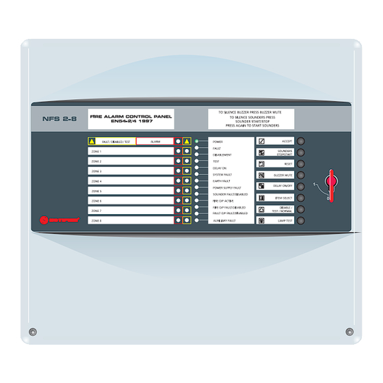
- Page 1 EN 54 & ISO 7240 2- 8 Zone Conventional Fire Control Panel Installation, Commissioning & Configuration Manual 997-492-000-5, Issue 5.0 For use with NFS 2-8 and FLS 2-8 Fire Control Panels...
- Page 2 NFS 2-8 Fire Control Panel FireLite FLS 2-8 Fire Control Panel...
-
Page 3: Table Of Contents
EN 54 & ISO 7240 2-8 Zone Conventional Fire Panel - Installation & Configuration Manual The following markings are used either on Contents the panel hardware or in the documentation. They have the following meaning: Introduction Manual Purpose ..........1 WARNING: Risk of electric shock. - Page 4 EN 54 & ISO 7240 2-8 Zone Conventional Fire Panel - Installation & Configuration Manual 6.3.4 2-Way Relay PCB (Optional) ....16 6.3.5 8-Way Relay PCB (Optional) ....16 6.3.6 4-Way Sounder PCB ........ 16 Powering the Panel ........17 6.4.1 Standby Batteries ........
-
Page 5: Manual Purpose
EN 54 (and ISO 7240) 2-8 Zone Conventional Fire Control Panel. The descriptions and procedures apply to the NFS 2-8 and FLS 2-8 fire control panels. Procedures described in this manual include appropriate... -
Page 6: Ce Marking
EN 54 & ISO 7240 2-8 Zone Conventional Fire Panel - Installation & Configuration Manual As a default, the panel is configured without delays to outputs. If delays are to be configured, refer to Section 7.8 Primary & Secondary Delays for details. While every effort is made to ensure the accuracy of the content of this manual, the manufacturer reserves the right to change the information without notice. -
Page 7: En54 Functions
EN 54 & ISO 7240 2-8 Zone Conventional Fire Panel - Installation & Configuration Manual 1.5 EN 54 Functions This fire control panel is designed to comply with the requirements of EN 54 Part 2/4. In addition to the basic requirements of EN 54-2, the panel may be configured to conform with the following optional functions - the applicable clauses of these standards are referenced as follows:... -
Page 8: Ancillary Functions
EN 54 & ISO 7240 2-8 Zone Conventional Fire Panel - Installation & Configuration Manual The following features are provided by the Power Supply Unit (PSU) of the NFS 2-8 and FLS 2-8 fire control panels to comply with EN 54-4 and ISO 7240-4. -
Page 9: Installation Guide
EN 54 & ISO 7240 2-8 Zone Conventional Fire Panel - Installation & Configuration Manual Installation Guide 2.1 How to Use this Guide This Installation Guide provides you with simple guidelines to install a fire control panel system, quickly and safely. The guide does not describe panel configuration procedures as it is covered by the relevant section of this manual. -
Page 10: Transient Protection
EN 54 & ISO 7240 2-8 Zone Conventional Fire Panel - Installation & Configuration Manual e) DO NOT locate the panel where there are high levels of vibration or shock f) DO NOT site the panel where there would be restricted access to the internal equipment and cabling/wiring connections. -
Page 11: Product Inspection
EN 54 & ISO 7240 2-8 Zone Conventional Fire Panel - Installation & Configuration Manual 2.4 Product Inspection The 2-8 Zone Fire control panel is simple to install and Check for damage commission if the recommended procedures described in this Installation Guide, and the Installation and before proceeding with Commissioning sections of this manual, are followed. -
Page 12: Installation Preparation
EN 54 & ISO 7240 2-8 Zone Conventional Fire Panel - Installation & Configuration Manual 2.5 Installation Preparation This section describes making the panel ready for installation. 2.5.1 Removing the Cover Remove the front cover as follows: Use the supplied 4mm hexagonal socket wrench to release the two recessed, socket-headed screws located in position ‘A’... -
Page 13: Optional Equipment
EN 54 & ISO 7240 2-8 Zone Conventional Fire Panel - Installation & Configuration Manual 2.6 Optional Equipment 2.6.1 2-Way Relay PCB An optional PCB supporting Fire and Fault condition, volt- free, status outputs may be fitted. When fitted, the PCB is connected to the Main PCB via connector, PL1. -
Page 14: Cabling Instructions
EN 54 & ISO 7240 2-8 Zone Conventional Fire Panel - Installation & Configuration Manual Cabling Cabling Instructions All wiring should comply with current IEE wiring WARNING Risk of electric regulations (BS7671) or the applicable local wiring shock. Before working on regulations. -
Page 15: Cable Terminations
EN 54 & ISO 7240 2-8 Zone Conventional Fire Panel - Installation & Configuration Manual 3.1.1 Cable Terminations This section provides guidance on where to bring cables into the back box for ease of termination. a. The mains supply should be brought into the control panel such that the live (L) and neutral (N) cable path to the mains termination block (MTB) is kept as short as possible. -
Page 16: Emc Considerations
(V eolmin = 20 - V eolmin drop The voltage must exceed the minimum specification of the sounders, i.e. 15V for the Notifier NS14. 997-492-000-5, Issue 5 June 2009... -
Page 17: Field Devices
EN 54 & ISO 7240 2-8 Zone Conventional Fire Panel - Installation & Configuration Manual Field Devices The Fire Control Panel is capable of working with various manucturer’s field devices (for compatible field devices refer to Section 1 Introduction). Each of these devices is supplied with an instruction leaflet showing the correct interconnections for various applications. -
Page 18: Panel Electronics
EN 54 & ISO 7240 2-8 Zone Conventional Fire Panel - Installation & Configuration Manual Panel Electronics The Fire Control Panel is supplied with the following factory-fitted electronic equipment: • Main PCB • PSU PCB These PCBs do not need to be removed to install the back box. -
Page 19: Psu Pcb
EN 54 & ISO 7240 2-8 Zone Conventional Fire Panel - Installation & Configuration Manual Refitting the Main PCB The procedure for refitting the Main PCB is the reverse of the removal procedure but note the following points: When offering the Main PCB to the three locating tabs (C) make sure that: Make the ribbon cable connection at socket connector SK4 (D) and re-connect the earth lead to the blade... -
Page 20: Commissioning Introduction
EN 54 & ISO 7240 2-8 Zone Conventional Fire Panel - Installation & Configuration Manual Commissioning 6.1 Introduction It is recommended that the control panel is powered up and tested before connecting the field devices. 6.2 Preliminary Checks Before connecting the mains power to the panel, check: 1 The earth lead from the safety earth post is connected to the earth tag on the Main PCB. -
Page 21: Powering The Panel
EN 54 & ISO 7240 2-8 Zone Conventional Fire Panel - Installation & Configuration Manual 6.4 Powering the Panel Before applying mains power to the control panel make sure that you carry out the following checks and procedures: 1 Check that you carried out all the instructions described in Section 6.2 Preliminary Checks. - Page 22 EN 54 & ISO 7240 2-8 Zone Conventional Fire Panel - Installation & Configuration Manual 2 Connect the batteries using the provided items: a. Red battery lead (1 off) b. Black battery lead (1 off) c. Short battery interlink lead (1 off). One end of each battery lead is fitted with a connector.
- Page 23 EN 54 & ISO 7240 2-8 Zone Conventional Fire Panel - Installation & Configuration Manual Recommended Battery Size The recommended battery sizes are given in the table below. The table is in two parts: the top part recommends battery sizes when 0.47μF capacitor EOL devices are used with 2, 4 or 8 zone panels and with 24hr or 72hr battery backup.
-
Page 24: Configuration And Handover
EN 54 & ISO 7240 2-8 Zone Conventional Fire Panel - Installation & Configuration Manual 6.5 Configuration and Handover After all external wiring has been connected to the panel CAUTION - Heat Hazard! and with no faults existing, the panel can be configured Under certain fault conditions for the particular system requirements. - Page 25 EN 54 & ISO 7240 2-8 Zone Conventional Fire Panel - Installation & Configuration Manual all detectors located between the removed device and the panel. Although the use of a capacitor EOL device meets the requirements of the standards, method 2 should be used when alarm latching of all detectors is required with one removed.
-
Page 26: Sounder Circuits
EN 54 & ISO 7240 2-8 Zone Conventional Fire Panel - Installation & Configuration Manual 6.8 Sounder Circuits Two sounder output circuits are provided. The termination block, TB1, for the sounder circuits is located at the top left-hand corner of the PSU PCB. DO NOT CONNECT UNTIL ALL ZONES HAVE BEEN CONFIGURED AND TESTED. -
Page 27: Digital Inputs
EN 54 & ISO 7240 2-8 Zone Conventional Fire Panel - Installation & Configuration Manual 6.9 Digital Inputs Two digital input circuits are provided. Terminal block, TB5, is provided on the Main PCB for these input circuits. Each circuit is configurable, at access Level 3, as a dedicated input function - refer to Section 7.7 Digital Inputs for details. -
Page 28: Fault Finding Chart
EN 54 & ISO 7240 2-8 Zone Conventional Fire Panel - Installation & Configuration Manual 6.10 Fault Finding Chart Use this chart to identify the cause of possible problems when commissioning your system. Indication Possible Cause Action No indication on panel - buzzer No power to panel. -
Page 29: Configuration
EN 54 & ISO 7240 2-8 Zone Conventional Fire Panel - Installation & Configuration Manual Configuration Access Level 3 allows input, output and control functions ISO 7240-2 : 14.5.3e), f) to be configured. Installers must make a record of the configuration The following sections describe how to configure the details of the panel and store panel. -
Page 30: Panel Options - A
EN 54 & ISO 7240 2-8 Zone Conventional Fire Panel - Installation & Configuration Manual 7.2 Panel Options - A Four user-configurable panel options are available: a. Enable/Disable Engineering Mute b. Enable/Disable Commissioning Mode c. ACCEPT pushbutton access level d. LAMP TEST pushbutton access level. e. -
Page 31: Mains Fault Delay
EN 54 & ISO 7240 2-8 Zone Conventional Fire Panel - Installation & Configuration Manual Non-latching only affects the following fault conditions: a. Zone Faults b. Earth Fault c. Power Supply Fault d. Sounder Fault e. Fire Output Fault f. Fault Output Fault g. -
Page 32: Fire Zone Input Type
EN 54 & ISO 7240 2-8 Zone Conventional Fire Panel - Installation & Configuration Manual 7.5 Fire Zone Input Type Fire input zones can be configured as follows: Latching/non-latching alarms Alarm or for short-circuit operation Auto or manual operation mode Coincident-alarm or separate-alarm detection Setting a Sprinkler Verification Time. -
Page 33: Sprinkler Verification Time
EN 54 & ISO 7240 2-8 Zone Conventional Fire Panel - Installation & Configuration Manual 7.5.5 Sprinkler Verification Time A 2 sec. verification time is applied to all inputs to reduce EN 54-2: & ISO 7240-2: the occurrence of false indications of alarm due to transient 7.1.3 phenomena. -
Page 34: Select Output
EN 54 & ISO 7240 2-8 Zone Conventional Fire Panel - Installation & Configuration Manual sounder output PCB, NFS-SST(English PN: 020-769- 001) or NFS8V-SST (German PN: 020-769) Display Boxes and Routing Termination kit (020-773). vi If an EN 54-2 or ISO 7240-2, 8.9 monitored fault routing output is required both relay and PSU PCB sounder outputs are unmonitored in this mode. -
Page 35: Select Input
EN 54 & ISO 7240 2-8 Zone Conventional Fire Panel - Installation & Configuration Manual g. Fault transmission failed return signal. Class Change: When a class change digital input is activated, all outputs configured as sounders will be activated until the input condition is removed. Alert: When an alert digital input is activated, all outputs configured as sounders and the internal buzzer start pulsing. -
Page 36: Primary And Secondary Delays
EN 54 & ISO 7240 2-8 Zone Conventional Fire Panel - Installation & Configuration Manual 7.8 Primary and Secondary Delays A day-time delay strategy can be implemented, if required, which comprises two user-configurable delay periods to allow a fire search to take place. These delay periods are referred to as primary and secondary. -
Page 37: Configuration Examples
EN 54 & ISO 7240 2-8 Zone Conventional Fire Panel - Installation & Configuration Manual 7.9 Configuration Examples The following examples are provided to offer guidance when navigating through some of the menu options. Note: If you lose your way at any time, simply press the ‘main menu’... -
Page 38: Specification
EN 54 & ISO 7240 2-8 Zone Conventional Fire Panel - Installation & Configuration Manual Specification General The Fire Control Panel meets the requirements of EN 54-2/ 4 and ISO 7240-2/4. See Section 1.4 CE Marking for further details. Mechanical: Construction: Fire-resistant, ABS plastic moulded front cover and back box. - Page 39 EN 54 & ISO 7240 2-8 Zone Conventional Fire Panel - Installation & Configuration Manual Electrical: Classification: A combination of Installation Class 1 and Class 2 (panel must be earthed). Conductor size: Compatible with cable conductor sizes: 0.5mm to 2.5mm Supply Rating: Mains supply to the panel is to be provided via an external, double-pole, mains-isolation unit.
- Page 40 EN 54 & ISO 7240 2-8 Zone Conventional Fire Panel - Installation & Configuration Manual Outputs: Sounder Circuits: EN 54-13 : 5.3.4.1, 5.3.4.2 Two outputs configurable as sounder, fire routing output or PSU PCB circuits do not fault output and each rated at 0.5A. The sounder and fire comply with the routing outputs are monitored.
- Page 41 EN 54 & ISO 7240 2-8 Zone Conventional Fire Panel - Installation & Configuration Manual by EN 54-13. A fault of the 4-way sounder PCB is indicated by the Auxiliary fault indicator. The following output options are configurable: - Sounder output - ÜE transmission circuit - Fire protection output (SST) - Fire routing output...
-
Page 42: Battery Calculation
EN54 & ISO 7240 2-8 Zone Conventional Fire Panel - Installation & Configuration Manual Battery Calculation The table in Section 6.4.1 Standby Batteries can be used to select the correct battery size. If full calculations are required use the procedure below. General Data PSU size Maximum...
Need help?
Do you have a question about the NFS 2-8 and is the answer not in the manual?
Questions and answers