Sign In
Upload
Download
Table of Contents
Contents
Add to my manuals
Delete from my manuals
Share
URL of this page:
HTML Link:
Bookmark this page
Add
Manual will be automatically added to "My Manuals"
Print this page
×
Bookmark added
×
Added to my manuals
Manuals
Brands
Notifier Manuals
Control Panel
NFS-320
Operation manual
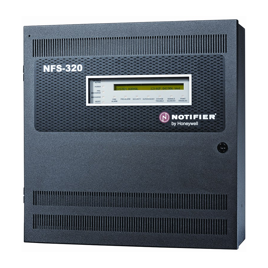
Notifier NFS-320 Operation Manual
Fire alarm control panel
Hide thumbs
Also See for NFS-320
:
Installation manual
(64 pages)
1
2
3
4
Table Of Contents
5
6
7
8
9
10
11
12
13
14
15
16
17
18
19
20
21
22
23
24
25
26
27
28
29
30
31
32
33
34
35
36
37
38
39
40
41
42
43
44
45
46
47
48
49
50
51
52
53
54
55
56
57
58
59
60
61
62
63
64
65
66
67
68
69
70
71
72
73
74
75
76
page
of
76
Go
/
76
Contents
Table of Contents
Bookmarks
Table of Contents
Fire Alarm System Limitations
Installation Precautions
Table of Contents
Section 1: General Information
UL 864 Compliance
About this Manual
1: Cautions and Warnings
2: Typographic Conventions
3: Supplemental Information
4: Shortcuts to Operating Functions
Introduction to the Control Panel
Section 2: Use of the Controls
Introduction
System Status Indicator Leds
Control Keys
1: Acknowledge/Scroll Display
2: Signal Silence
3: System Reset
4: Drill
5: Lamp Test
Programming Keypad
Section 3: Operation of the Control Panel
Overview
Normal Mode of Operation
Fire Alarm Mode of Operation
1: How the Control Panel Indicates a Fire Alarm
2: How to Respond to a Fire Alarm
3: Interpreting Fire Alarm Type Codes
Carbon Monoxide (CO) Alarm Mode of Operation
1: How the Control Panel Indicates a CO Alarm
2: How to Respond to a CO Alarm
3: Interpreting CO Alarm/Supervisory Type ID Codes
System Trouble Mode of Operation
1: How the Control Panel Indicates a System Trouble
2: How to Respond to a System Trouble
Security Alarm Mode of Operation
1: How the Control Panel Indicates a Security Alarm
2: How to Respond to a Security Alarm
System Trouble Mode of Operation
3: Interpreting Security Type Codes
Active Supervisory Signal Mode of Operation
1: How the Control Panel Indicates an Active Supervisory
2: How to Respond to an Active Supervisory
3: How to Interpret Supervisory Type Codes
Pre-Alarm Warning Mode of Operation
1: How the Control Panel Indicates a Pre-Alarm Warning
2: How to Respond to a Pre-Alarm Warning
Disabled Points Mode of Operation
Non-Alarm Mode of Operation
1: Purpose of Non-Alarm Points
2: How the Control Panel Indicates an Active Fire Control
3: How the Control Panel Indicates an Active Non-Fire Point
Active Trouble Monitor Mode of Operation
1: How the Control Panel Indicates an Active Trouble Monitor
2: How to Respond to an Active Trouble Monitor
Output Circuit Trouble Mode of Operation
1: Overview
2: How the Control Panel Indicates a NAC Trouble
3: How the Control Panel Indicates a Control/Relay Trouble
4: How to Respond to a NAC or Control/Relay Trouble
Operation of Special System Timers
1: What Are System Timers
2: How to View System Timer Selections
3: How System Timers Work
Waterflow Circuit Operation
Style 6 and Style 7 Operation
Section 4: Read Status Operation
Introduction
What Is Read Status
1: Quick Reference Key Sequences
Entering Read Status
Viewing and Printing a Read Status
1: How to View Read Status of Devices, Zones, & System Settings
2: How to View Read Status for Event and Alarm History
3: How to Print Points, Event and Alarm History
4: How to View and Print Hidden Event and Alarm History
Appendix A, "Special Zone Operation
A.1: Overview
A.2: Releasing Zones (R0-R9)
A.2.1: Purpose of Releasing Zones
A.2.2: How to View Releasing Zone Selections
A.2.3: How Releasing Zones Operate
A.3: Time, Date, and Holiday Functions
A.3.1: Overview
A.3.2: How to View Time Control Selections
A.3.3: How to View Holiday Function Selections
A.3.4: How Time Control and Holiday Functions Work
A.4: NAC Coding
A.4.1: Overview of Coding
A.4.2: How to View Coding (F8) Selections
A.4.3: How to Respond to an Alarm with Coding
A.5: Presignal and Positive Alarm Sequence (PAS) Operation
A.5.1: Overview
A.5.2: What Is Presignal and PAS
A.5.3: How to View Presignal and PAS Selections
A.5.4: How to Respond to an Alarm with Presignal Delay Timer (no PAS)
A.5.5: How to Respond to an Alarm with Presignal Delay Timer (PAS Selected)
Appendix A: Special Zone Operation
Appendix B, "Intelligent Detector Functions
Appendix B: Intelligent Detector Functions
Appendix C: Remote Terminal Access
C.1: General Description
C.2: Operating Modes
C.2.1: Local Terminal Mode (Loct)
C.2.2: Local Monitor Mode (Locm)
C.2.3: Remote Terminal Mode (Remt)
C.3: Using the CRT-2 for Read Status
C.3.1: Overview
C.3.2: Accessing Read Status Options
Appendix C.3, "Remote Terminal Mode Functions
C.3.3: Read Point
C.3.4: Display Devices in Alarm or Trouble
C.3.5: Display All Programmed Points
C.3.6: Step-Through History
C.3.7: View All History
C.3.8: Step-Through Alarm History
C.3.9: View All Alarm History
C.4: Using the CRT-2 for Alter Status
C.4.1: Overview
C.4.2: Accessing Alter Status Options
C.4.3: Enable or Disable Detectors, Modules or Zones
C.4.4: Change Alarm and Pre-Alarm Levels
C.4.5: Clear Verification Counter
C.4.6: Clear the Entire History Buffer
C.4.7: Set the Pre-Alarm for Alert or Action
Appendix D: Point and System Troubles Lists
Appendix D, "Point and System Troubles Lists
D.1: Point (Device) Troubles
D.2: System Troubles
Index
Advertisement
Quick Links
1
D.2: System Troubles
Download this manual
See also:
Installation Manual
Fire Alarm Control Panel
NFS-320/E/C,
NFS-320SYS/E
Operations Manual
Document 52747
E1
06/16/2011
Rev:
P/N 52747:E1
ECN 11-336
Table of
Contents
Previous
Page
Next
Page
1
2
3
4
5
Advertisement
Table of Contents
Need help?
Do you have a question about the NFS-320 and is the answer not in the manual?
Ask a question
Questions and answers
Related Manuals for Notifier NFS-320
Control Panel Notifier NFS-320 Installation Manual
Fire alarm control panel (64 pages)
Control Panel Notifier NFS-C Operation Manual
Fire alarm control panel (76 pages)
Control Panel Notifier NFS-640 Installation Manual
Fire alarm control panel (88 pages)
Control Panel Notifier NFS-3030/E Installation Manual
Fire alarm control panel (68 pages)
Control Panel Notifier NFS-3030/E Operation Manual
Fire alarm control panel (72 pages)
Control Panel Notifier NFS2-640/E Operation Manual
Fire alarm control panel (76 pages)
Control Panel Notifier NFS2-640/E Installation Manual
Fire alarm control panel (78 pages)
Control Panel Notifier NFS2-3030/E Installation Manual
Fire alarm control panel (68 pages)
Control Panel Notifier NFS2-3030 Operation Manual
Fire alarm control panel (95 pages)
Control Panel Notifier NFS2-3030 Operation And Maintenance Manual
Intelligent addressable fire alarm system (30 pages)
Control Panel Notifier NFS 2-8 Installation, Commissioning & Configuration Manual
En 54 & iso 7240 2- 8 zone conventional fire control panel (43 pages)
Control Panel Notifier AFP-2800 Operation, Installation & Programming Manual
Intelligent, analogue addressable panel with non-proprietary programming tools (158 pages)
Control Panel Notifier AM-6000 Installation Manual
Analog fire alarm control panel (32 pages)
Control Panel Notifier AFP-300 Programming Manual
Analog fire panel (48 pages)
Control Panel Notifier AFP-300 Installation Manual
Analog fire panel (207 pages)
Control Panel Notifier Fire Alarm Control Panel Operating Manual
Fire alarm control panel (34 pages)
This manual is also suitable for:
Nfs-c
Nfs-320sys
Nfs-e
Nfs-320syse
Nfs-320e
Nfs-320c
Table of Contents
Save PDF
Print
Rename the bookmark
Delete bookmark?
Delete from my manuals?
Login
Sign In
OR
Sign in with Facebook
Sign in with Google
Upload manual
Upload from disk
Upload from URL


Need help?
Do you have a question about the NFS-320 and is the answer not in the manual?
Questions and answers