Notifier NFS2-3030 Operation Manual
Fire alarm control panel
Hide thumbs
Also See for NFS2-3030:
- Installation manual (68 pages) ,
- Operating instructions (1 page) ,
- Operation and maintenance manual (30 pages)

Related Manuals for Notifier NFS2-3030


Summary of Contents for Notifier NFS2-3030
- Page 1 Fire Alarm Control Panel NFS2-3030 Operations Manual Document 52546 06/20//2014 Rev: P/N 52546:N1 ECN 13-0838...
- Page 2 Adequate written records of all inspections should be kept. (especially in bedrooms), smoking in bed, and violent explosions Limit-D-1-2013 NFS2-3030 Operations Manual — P/N 52546:N1 06/20//2014...
-
Page 3: Installation Precautions
HARSH™, NIS™, and NOTI•FIRE•NET™ are all trademarks; and Acclimate® Plus, FlashScan®, NION®, NOTIFIER®, ONYX®, ONYXWorks®, UniNet®, VeriFire®, and VIEW® are all registered trademarks of Honeywell International Inc. Echelon® is a registered trademark and LonWorks™ is a trademark of Echelon Corporation. - Page 4 •Brief description of content you think should be improved or corrected •Your suggestion for how to correct/improve documentation Send email messages to: FireSystems.TechPubs@honeywell.com Please note this email address is for documentation feedback only. If you have any technical issues, please contact Technical Services. NFS2-3030 Operations Manual — P/N 52546:N1 06/20//2014...
- Page 5 2.7.3: Interpreting Type ID Codes.......................41 2.8: CO Pre-alarm Event.............................42 2.8.1: How the Control Panel Indicates a CO Pre-alarm................42 2.8.2: How to Respond to a CO Pre-Alarm Warning ..................42 2.8.3: Interpreting Type ID Codes.......................43 NFS2-3030 Operations Manual — P/N 52546:N1 06/20//2014...
- Page 6 Appendix A: Software Type ID Codes .................. 78 A.1: Alphabetical List ............................78 Appendix B: Releasing Zones ....................82 B.1: Introduction ..............................82 B.2: How Releasing Zones Operate ........................83 Section C: Factory Mutual Applications ................86 Index ............................88 NFS2-3030 Operations Manual — P/N 52546:N1 06/20//2014...
-
Page 7: Section 1: General Information
1.2 Related Documents The table below provides a list of document sources (manuals) containing additional information regarding the NFS2-3030 and optional peripherals. The NOTIFIER document (DOC-NOT) pro- vides the current document revision. A copy of this document is included in every shipment. - Page 8 UZC-256 Universal Zone Coder Manual 15216 UZC-256 Programming Manual 15976 XP Transponder Manual 15888 XP10-M Ten Input Monitor Module Installation Document I56-1803 XP5 Series Manual 50786 Table 1.1 Related Documents (2 of 3) NFS2-3030 Operations Manual — P/N 52546:N1 06/20//2014...
-
Page 9: About This Manual
1.4 Introduction to the Control Panel The NFS2-3030 is an intelligent Fire Alarm Control Panel (FACP) with features suitable for most applications. The CPU2-3030 comes with a front display/keypad option, which allows program- ming and viewing options at the panel. -
Page 10: Operating Features
Programmable Control-By-Event control of outputs from individual alarm or supervisory addressable devices • Networks with other FACPs and equipment for large applications • Automatic detector sensitivity adjustments based on programmable building occupancy schedules • Compatible with Mass Notification Systems NFS2-3030 Operations Manual — P/N 52546:N1 06/20//2014... -
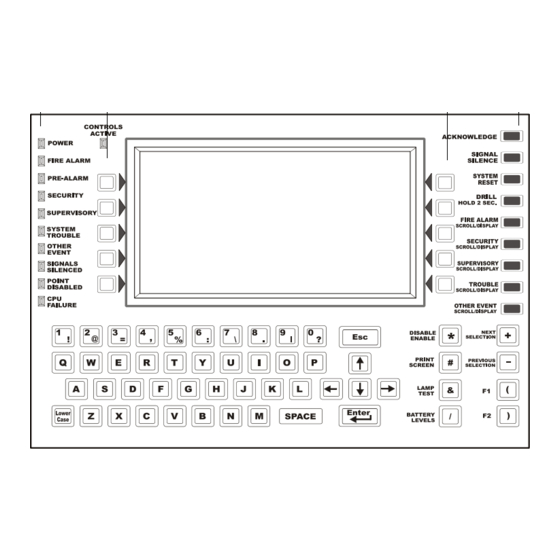
Page 11: The Display/Keypad
Fields may be entered or changed and commands may be issued on the display using the keypad. The Keypad The keypad has several types of keys, described below. NFS2-3030 Operations Manual — P/N 52546:N1 06/20//2014... - Page 12 60 seconds network.) If both Fire and Mass Notification events exist on the fire panel at the same time, a second System Reset will need to be performed to reset the fire panel. The NFS2-3030 will display MN SYSTEM RESET FIRE , depending on which event has priority.
-
Page 13: Led Indicators
Signals Silenced Yellow Illuminates if the NFS2-3030 Notification Appliances have been silenced. It flashes if some but not all of the NFS2-3030 NACs have been silenced. Point Disabled Yellow Illuminates when at least one device has been disabled. It will flash until all disabled points have been acknowledged. -
Page 14: Message Formats
The top four lines contain the event and point information. Event counts display in the next three lines, the current time and soft key information appears after the event counts. NFS2-3030 Operations Manual — P/N 52546:N1 06/20//2014... - Page 15 The event counts display shows the counts for outstanding events. The date in line eight gives the current time. The soft keys may be used to deal with the event; their functions are described in the Operation section of this manual. NFS2-3030 Operations Manual — P/N 52546:N1 06/20//2014...
- Page 16 When a local mass notification event occurs on the fire panel, a message is generated to the panel that displays on the top of the LCD screen, and soft keys display available functions that may be used to handle the event. NFS2-3030 Operations Manual — P/N 52546:N1 06/20//2014...
- Page 17 S Y S T E M R E S E T P R O G R A M / A L T E R S T A T U S B A C K Figure 1.5 Network Mass Notification Event Example NFS2-3030 Operations Manual — P/N 52546:N1 06/20//2014...
-
Page 18: Navigating Menu And Programming Screens
Event Counts screen. This screen will automatically display if an off-normal event requiring acknowledgement occurs, unless the panel is in programming mode. Fire alarm events will display even in programming mode. NFS2-3030 Operations Manual — P/N 52546:N1 06/20//2014... -
Page 19: More Information
This screen will require a password. For program- ming instructions, refer to the NFS2-3030 Programming Manual. SIGNAL SILENCE - Press this key to silence all NFS2-3030 outputs programmed as silenceable. SYSTEM RESET - Press this key to reset the system. - Page 20 The drift compensation tolerance value has been exceeded. For FSC-851 IntelliQuad detectors in CLIP mode, the status will display as None/Very Clean until it displays Needs Immediate Cleaning. No intermediate levels are displayed. NFS2-3030 Operations Manual — P/N 52546:N1 06/20//2014...
-
Page 21: Multiple Event List
Using the Next Selection/Previous Selection special function keys to scroll through the list will replace the event at the top of the screen with the first event in the series displayed below it. NFS2-3030 Operations Manual — P/N 52546:N1 06/20//2014... - Page 22 For USA event ordering - the Event Count Screen will appear with the Acknowledge button only. Acknowledging the event(s) will bring the Multiple Event list back up. For Canadian event ordering - the Multiple Event list screen will display the unacknowledged event at the top. NFS2-3030 Operations Manual — P/N 52546:N1 06/20//2014...
-
Page 23: History Display (History Select Screen)
Reports”, on page 69 for descriptions and illustrations. This key will appear only if a printer has been selected through programming. Refer to this panel’s programming manual for information on printer selection. NFS2-3030 Operations Manual — P/N 52546:N1 06/20//2014... -
Page 24: Section 2: Operation Of The Control Panel
Scans for any panel screen, keypad, and Control Key entries • Performs a detector automatic test operation • Tests system memory • Monitors for microcontroller failure No action is required of the operator when the panel is operating in Normal mode. NFS2-3030 Operations Manual — P/N 52546:N1 06/20//2014... -
Page 25: Acknowledging An Event
Activates the general alarm zone (Z000) NOTE: If a monitor module programmed with a Type Code initiates a fire alarm, the WATERFLOW control panel disables the key and the Auto Silence Timer. SIGNAL SILENCE NFS2-3030 Operations Manual — P/N 52546:N1 06/20//2014... -
Page 26: How To Respond To A Fire Alarm
NFS2-3030 Programming Manual for event priority programming information. The soft key PROGRAM/ALTER STATUS is also displayed on this screen. A password is required to enter these menus, which are described in the NFS2-3030 Programming Manual. 2.2.3 Interpreting Type ID Codes The Type ID code that displays in the fire alarm message is related to the type and function of the point that initiates the fire alarm. -
Page 27: System Or Point Trouble Event
P R O G R A M / A L T E R S T A T U S M A I N M E N U Figure 2.3 Sample Message for System Trouble NFS2-3030 Operations Manual — P/N 52546:N1 06/20//2014... -
Page 28: How To Respond To A System Or Point Trouble
A message from the “Trouble Type” column in Table 2.1, “Point (Device) Troubles,” on page 29 will appear in the upper right corner of the panel display when a point (device) trouble occurs. Use this table to help determine what the trouble is. NFS2-3030 Operations Manual — P/N 52546:N1 06/20//2014... - Page 29 The DVC is currently downloading to a DAL device. DAL DUAL ADDRESS More than one DAL device has the same address. Re-address DAL device(s). CONFLICT Table 2.1 Point (Device) Troubles (1 of 4) NFS2-3030 Operations Manual — P/N 52546:N1 06/20//2014...
- Page 30 Inspect the pipes for damage or clogging. LOW TEMPERATURE The temperature read by a Heat+ or Acclimate™+ Raise the heat in the area of the detector. detector is too low. Table 2.1 Point (Device) Troubles (2 of 4) NFS2-3030 Operations Manual — P/N 52546:N1 06/20//2014...
- Page 31 Investigate and correct the software revision. MISMATCH the fire alarm control panel, or devices installed on the system are programmed with software that is incompatible with each other. Table 2.1 Point (Device) Troubles (3 of 4) NFS2-3030 Operations Manual — P/N 52546:N1 06/20//2014...
- Page 32 The audio library version is incompatible with the database and/or the application version. AUXILIARY TROUBLE Auxiliary device connected to the NFS2-3030 CPU at J5 is in trouble or cable is missing. Table 2.2 System Troubles (1 of 4) NFS2-3030 Operations Manual — P/N 52546:N1 06/20//2014...
- Page 33 The internal RAM test failed. Service required. INVALID NODE TYPE MAPPED An invalid node type has been mapped to the NFS2-3030 for Network Display Mode. Check network mapping and correct. Refer to the NFS2-3030 Programming Manual for valid network types.
- Page 34 NETWORK INCOMPATIBILITY An incompatible product exists on this network. NETWORK MAPPING LIMIT More than 1 fire panel or more than 4 DVCs has been mapped to the NFS2-3030 for Network Display Mode. EXCEEDED Check network mapping and correct. NFN PAGING CHANNEL LIMIT Multiple paging sources are attempting to page over the NFN, exceeding the limit of one (1).
-
Page 35: Interpreting Type Id Codes
LCD, as well as the sensitivity reading, the PREALARM type code and other information specific to the detector as shown in Figure 2.5. • Sends a Pre-alarm message to the History buffer, installed printer and annunciators. NFS2-3030 Operations Manual — P/N 52546:N1 06/20//2014... - Page 36 S Y S T E M R E S E T P R O G R A M / A L T E R S T A T U S M A I N M E N U Figure 2.5 Sample Pre-alarm Message NFS2-3030 Operations Manual — P/N 52546:N1 06/20//2014...
-
Page 37: How To Respond To A Pre-Alarm Warning
A subsequent alarm condition for this detector clears the Action indication from the panel display. The soft key PROGRAM/ALTER STATUS is also displayed on this screen. A password is required to enter these menus, which are described in the NFS2-3030 Programming Manual. 2.4.3 Interpreting Type ID Codes The Type ID code that displays in a pre-alarm message is related to the type and function of the detector point that initiates the pre-alarm. -
Page 38: How To Respond To A Security Alarm
The soft key PROGRAM/ALTER STATUS is also displayed on this screen. A password is required to enter these menus, which are described in the NFS2-3030 Programming Manual. 2.5.3 Interpreting Security Type Codes The Type ID code that displays in a security alarm message is related to the type and function of the point that initiates the security alarm. -
Page 39: Supervisory Signal Event
Press the MORE INFORMATION soft key to display the MORE INFORMATION screen and view additional information on the device and possibly preprogrammed text for recommended action. (Refer to Figure 1.8 on page 19 for an example of this screen and an explanation of its fields.) NFS2-3030 Operations Manual — P/N 52546:N1 06/20//2014... -
Page 40: How To Interpret Type Codes
Latches the control panel in CO alarm. (You cannot return the control panel to normal operation until you correct the alarm condition and reset the control panel) • Initiates any Control-By-Event actions. Activates CBE position 4. • Activates Special Function Zone 18 (ZF18) NFS2-3030 Operations Manual — P/N 52546:N1 06/20//2014... -
Page 41: How To Respond To A Co Alarm
The soft key PROGRAM/ALTER STATUS is also displayed on this screen. A password is required to enter these menus, which are described in the NFS2-3030 Programming Manual. 2.7.3 Interpreting Type ID Codes The Type ID code that displays in the CO alarm message is related to the type and function of the point that initiates the CO alarm. -
Page 42: Co Pre-Alarm Event
Investigate and correct the condition causing the CO Pre-alarm. The soft key PROGRAM/ALTER STATUS is also displayed on this screen. A password is required to enter these menus, which are described in the NFS2-3030 Programming Manual. NFS2-3030 Operations Manual — P/N 52546:N1 06/20//2014... -
Page 43: Interpreting Type Id Codes
If a fire condition is present on the control panel, a second system reset may be required to clear the MN alarm, depending on MN Priority programming. Refer to the NFS2-3030 Programming Manual. •... -
Page 44: How To Respond To An Mn Alarm
MN events, a second reset must be initiated to clear the MN alarm from the panel. The soft key PROGRAM/ALTER STATUS is also displayed on this screen. A password is required to enter these menus, which are described in the NFS2-3030 Programming Manual. 2.9.3 Interpreting Type ID Codes The Type ID code that displays in the fire alarm message is related to the type and function of the point that initiates the fire alarm. -
Page 45: How To Respond To An Active Mn Supervisory
For latching MN Supervisory events: If the supervisory condition was initiated by a device that is programmed with an MN supervisory type code that latches upon activation or a General MN Supervisory event occurs, press the SYSTEM RESET soft key to clear the event. NFS2-3030 Operations Manual — P/N 52546:N1 06/20//2014... -
Page 46: How To Interpret Type Codes
When an unacknowledged event with a higher priority exists, the control panel retains the indications of the higher priority event (the message, lit LED, audible tone, etc.) while flashing the LED, and sending a Trouble message to the history buffer, installed printer and SYSTEM TROUBLE annunciators. NFS2-3030 Operations Manual — P/N 52546:N1 06/20//2014... -
Page 47: How To Respond To A Mass Notification Trouble
Restores troubles automatically - even if troubles are not acknowledged The soft key PROGRAM/ALTER STATUS is also displayed on this screen. A password is required to enter these menus, which are described in this panel’s programming manual. NFS2-3030 Operations Manual — P/N 52546:N1 06/20//2014... -
Page 48: Disabled Points Event
Figure 2.13 Sample Disabled Point Message Soft Keys ACKNOWLEDGE: Press to acknowledge the disable message. MORE INFORMATION: Press to view more information on the disabled point. PROGRAM/ALTER STATUS: A password is required to enter these menus. NFS2-3030 Operations Manual — P/N 52546:N1 06/20//2014... -
Page 49: Active Event
The onboard trouble relay and municipal box output will activate when the countdown is complete. Note that this panel notifies the central station communicator as soon as AC failure occurs, and the central station communicator follows its own programmed schedule for reporting the failure. NFS2-3030 Operations Manual — P/N 52546:N1 06/20//2014... -
Page 50: Presignal
15 seconds, the control panel will enter Presignal mode as described above. The PAS Inhibit switch can be used to turn off the PAS delay timer when the control panel is unat- tended. NFS2-3030 Operations Manual — P/N 52546:N1 06/20//2014... -
Page 51: Section 3: Read Status
(01 through 32), S indicates DAA speaker circuit, n=DAA speaker circuit (A, B, C or D). Release Zone NxxxZRyy R=Releasing Zone, yy=Releasing Zone number (00-09) Table 3.1 Address Formats (1 of 2) NFS2-3030 Operations Manual — P/N 52546:N1 06/20//2014... -
Page 52: Smoke Detector
Lines 1- 4 - This could display any current event message, or, as in this example, the System Nor- mal message. Line 5 - This line contains the screen title and the address of the point being read. NFS2-3030 Operations Manual — P/N 52546:N1 06/20//2014... - Page 53 Lines 11 through 14 - These lines display only if the device being read is a smoke, heat, or aspira- tion detector. Refer to Section 1.8.2, “More Information”, on page 19 for an explanation of these fields. Line 16 - Press to return to the previous screen. B A C K - NFS2-3030 Operations Manual — P/N 52546:N1 06/20//2014...
-
Page 54: Heat Detector
1 0 : 2 2 : 3 4 A T U E J A N 2 5 , 2 0 1 1 B A C K Figure 3.4 Photo/CO Smoke Detector Screen - Read Status NFS2-3030 Operations Manual — P/N 52546:N1 06/20//2014... - Page 55 Line 14 - CO - This field represents the level of Carbon Monoxide for the device. The value is in parts per million. Line 15 - The current time and date are displayed in this line. Line 16 - Press to return to the previous screen. B A C K NFS2-3030 Operations Manual — P/N 52546:N1 06/20//2014...
-
Page 56: Aspiration Detector
T U E J A N 2 5 , 2 0 1 1 AMPS-24, ACPS- B A C K 610/E, or an ACPS-2406. See text below. Figure 3.7 Monitor Module Screen - Read Status NFS2-3030 Operations Manual — P/N 52546:N1 06/20//2014... -
Page 57: Control Module
The point has been forced into manual control state by an outside source. MANUAL DISABLED A status change other than a change to MANUAL control has caused the point to go off automatic control. TROUBLE NFS2-3030 Operations Manual — P/N 52546:N1 06/20//2014... - Page 58 Line 14 - SWITCH INHIBIT: YES - Displays YES if the operator can not manually activate an output. Line 15 - The current time and date are displayed in this line. Line 16 - Press to return to the previous screen. B A C K NFS2-3030 Operations Manual — P/N 52546:N1 06/20//2014...
-
Page 59: General Zone
1 0 : 2 2 : 3 4 A T U E J A N 2 5 , 2 0 1 1 B A C K Figure 3.10 Logic Zone Screen - Read Status NFS2-3030 Operations Manual — P/N 52546:N1 06/20//2014... -
Page 60: Releasing Zone
Line 12 - SOAK TIME - Displays the Soak Time setting; 0 to 9999 seconds. Line 15 - Displays the current time and date. For further information on Releasing Zones, refer to Appendix B of this manual. NFS2-3030 Operations Manual — P/N 52546:N1 06/20//2014... -
Page 61: Special Function Zone
Lines 1 through 6 - Refer to the descriptions in Section 3.2, “Smoke Detector”, on page 52. EQUATION: The equation for this trouble zone is displayed here. Line 15 - Current time and date. NFS2-3030 Operations Manual — P/N 52546:N1 06/20//2014... -
Page 62: Annunciator
Line 6 - Displays the annunciator mode. Line 7 - Displays the state of the active LED. Line 8 - Displays the state of the trouble LED. Line 10 - Displays the annunciator source(s). NFS2-3030 Operations Manual — P/N 52546:N1 06/20//2014... -
Page 63: Daa Speaker Circuit
Figure 3.16 PAM (Prioritized Audio Matrix) Point - Read Status Lines 1 - 6 - Refer to the line 6 description in “Smoke Detector” on page 52 Line 9 - DVC General Zone Map. NFS2-3030 Operations Manual — P/N 52546:N1 06/20//2014... - Page 64 SWITCH INHIBIT: - The screen will display the PAM point’s programmed setting for Switch Inhibit (Yes or No). SILENCEABLE: - The screen will display the PAM point’s programmed Silenceable setting (Yes or No). NFS2-3030 Operations Manual — P/N 52546:N1 06/20//2014...
-
Page 65: Section 4: Viewing And Printing History Information
The screen below is an example of what displays when the ALL EVENTS soft key is pressed. The displayed fields are the same for each event type. NFS2-3030 Operations Manual — P/N 52546:N1 06/20//2014... - Page 66 17 events). The report will look like this: ******EVENT HISTORY************************************************************* TROUBLE TM4 NO ANSWER 08:52:05P SAT MAR 5, 2011 ACK TROUBLE TM4 NO ANSWER 08:53:35P SAT MAR 5, 2011 CLEAR TROUBLE TM4 NO ANSWER 08:54:05P SAT MAR 5, 2011 ******************************************************************************** NFS2-3030 Operations Manual — P/N 52546:N1 06/20//2014...
-
Page 67: Time And Date Range Selection For All Events
Range is selected in the following order: Loop 1 Detectors Loop 2 Detectors, etc.… Loop 10 Detectors Loop 1 Modules Loop 2 Modules, etc. … NFS2-3030 Operations Manual — P/N 52546:N1 06/20//2014... - Page 68 ACCEPT: - When entries are made, press this soft key to proceed to the All Events in Range Screen. All Events in Range Screen This screen is the same as the Event History screen, except for its title. Refer to Figure 4.1 on page 66. NFS2-3030 Operations Manual — P/N 52546:N1 06/20//2014...
-
Page 69: Section 5: Printing Reports
Section 5: Printing Reports A variety of reports can be generated and printed from the NFS2-3030. Reports listing all event, alarm, trouble, supervisory, or security history can be generated from the history screens in Section 4, “Viewing and Printing History Information”, on page 65. The following section describes how to print programming, Walk Test, and active point information. - Page 70 Programmed prealarm sensitivity* prealarm alarm threshold* threshold* Programmed alarm sensitivity* * Whichever occupancy value is in effect when the report is printed. INSTALLED POINTS: Press this soft key to display the Installed Points Menu screen. NFS2-3030 Operations Manual — P/N 52546:N1 06/20//2014...
-
Page 71: Print Programming Menu Screen
******************************************************************************** TIMERS: Press to print timer values for Auto Silence, Silence Inhibit, AC Fail Delay time and whether it has been enabled, Proprietary Reminder, and Remote Reminder timers. The report looks like this: NFS2-3030 Operations Manual — P/N 52546:N1 06/20//2014... -
Page 72: Print Programming Menu Screen (2)
Figure 5.3 Print Programming Screen Soft Keys SUPERVISION: Press to print information on power supply and printer monitoring. The report looks like this: ******SUPERVISION*************************************************************** MAIN POWER SUPPLY ADDRESS: L01M006 PRINTER: 80-column TAMPER INPUT: AUXILIARY TROUBLE: ******************************************************************************** NFS2-3030 Operations Manual — P/N 52546:N1 06/20//2014... -
Page 73: Active Points Report Screen
The soft key will display on the screen only if there is at least one event in the queue. NOTE: For a printed list of history information, refer to the history screens in Section 4, “Viewing and Printing History Information”. NFS2-3030 Operations Manual — P/N 52546:N1 06/20//2014... -
Page 74: Installed Points Report Screen
Point label, Message or Module Co-op extended label Addresses NORMAL SMOKE (ION) Detector L02D129 *** *** NTL*Y *** ** 6666 Z002 L02D129 Device Ten zone fields of zone map (separated by commas) Address NFS2-3030 Operations Manual — P/N 52546:N1 06/20//2014... - Page 75 RELEASE ZONE ******************************************************************************** SPECIAL ZONES: Press to print a report of installed releasing zones. An asterisk in this position indicates this zone appears in a point’s zone map. ******INSTALLED POINTS********************************************************** SPECIAL ZONE ZF0* ******************************************************************************** NFS2-3030 Operations Manual — P/N 52546:N1 06/20//2014...
- Page 76 Printing Reports Installed Points Report Screen TROUBLE ZONES: Press to print a report of installed trouble zones. ******INSTALLED POINTS********************************************************** TROUBLE ZONE OR(ZT049,ZT050) ******************************************************************************** NFS2-3030 Operations Manual — P/N 52546:N1 06/20//2014...
- Page 77 ZONE, ACS PTS, SPECIAL ZONE, TROUBLE ZONE. Using the keypad, type in the start point address. END POINT: Press to place cursor in this field, and to toggle between the choices as described above. Using the keypad, type in the end point address. NFS2-3030 Operations Manual — P/N 52546:N1 06/20//2014...
-
Page 78: Appendix A: Software Type Id Codes
Appendix A: Software Type ID Codes A.1 Alphabetical List The following chart lists NFS2-3030 Type ID codes in alphabetical order. These codes are assigned during programming based on the types and functions of the devices they are assigned. The codes appear in point message formats. - Page 79 REL CKT ULC Control module used to direct outputs to perform a release function as required by ULC RELAY Form-C relay control module Table A.1 Software Type ID Codes, Alphabetical List (2 of 4) NFS2-3030 Operations Manual — P/N 52546:N1 06/20//2014...
- Page 80 Control module for standard telephone circuit TRACKING SUPERV Monitor for waterflow tamper switches for alarm points TROUBLE MON Monitor for trouble inputs Table A.1 Software Type ID Codes, Alphabetical List (3 of 4) NFS2-3030 Operations Manual — P/N 52546:N1 06/20//2014...
- Page 81 Monitor for supervisory condition for activated waterflow switch WEATHER ALRT Monitor for weather condition, tracking *Not suitable for Canadian applications. **Subject to AHJ approval. Table A.1 Software Type ID Codes, Alphabetical List (4 of 4) NFS2-3030 Operations Manual — P/N 52546:N1 06/20//2014...
-
Page 82: Appendix B: Releasing Zones
Select 0001-9999 seconds for Soak Time or 0000 seconds for no Soak Time. Table B.1 Releasing Options The Read Status function allows the operator to view the current selections for a Releasing Zone. Refer to Section 3.10, “Releasing Zone”, on page 60 for more information. NFS2-3030 Operations Manual — P/N 52546:N1 06/20//2014... -
Page 83: B.2: How Releasing Zones Operate
Figure B.1 Illustrated Example of Cross Zone Programming Listing of each Cross Zone option and the conditions required to activate the Releasing Zone, according to the example shown in Figure B.1 on page 83. NFS2-3030 Operations Manual — P/N 52546:N1 06/20//2014... - Page 84 • An alarm from L02D102 and L02D103 – detectors mapped to different zones, but both list ZR01 in their zone map. Cross=HEAT Activation of heat detector L02D104 and one smoke detector (L02D101, L02D102, or L02D103). Table B.2 Example of Cross Zone Selections NFS2-3030 Operations Manual — P/N 52546:N1 06/20//2014...
- Page 85 How Releasing Zones Operate Releasing Zones NFS2-3030 Operations Manual — P/N 52546:N1 06/20//2014...
-
Page 86: Section C: Factory Mutual Applications
The FMM-4-20’s 4-20 mA sensor has dropped below 4 NOTE: If the FMM-4-20 is monitoring a sensor that supports the Device Inhibit condition, it is recommended that the user program one of the 4-20 mA thresholds to support this condition. NFS2-3030 Operations Manual — P/N 52546:N1 06/20//2014... - Page 87 FMM-4-20 thresholds should be programmed to detect the Device Inhibit condition. NOTE: If the intensity of the LCD display on the fire panel needs to be increased or decreased to improve legibility, please refer to LCD Display Programming in the NFS2-3030 Programming Manual.
-
Page 88: Index
Panel indications 40 Report listing 73 CO Pre-alarm 42 Event Ordering 21 How to respond 42 Event ordering setting report 71 Panel indications 42 Event reporting format 14 Control Module point events 14 NFS2-3030 Operations Manual — P/N 52546:N1 06/20//2014... - Page 89 52 History Select 23 More Information 19 Multiple Event List 21 Off-normal events 24 Printer Functions 23 OTHER EVENT SCROLL/DISPLAY fixed Program/Alter Status 23 function key 12 Read Status 23 Manual Release 82 NFS2-3030 Operations Manual — P/N 52546:N1 06/20//2014...
- Page 90 12 Monitor Module 56 Supervisory Signal (Active Supervisory) Releasing Zone 60 How to respond 39 Special Function Zone 61 Panel indication 39 Trouble Zone 61 Supplemental Documentation 7 Receive Mode 12 NFS2-3030 Operations Manual — P/N 52546:N1 06/20//2014...
- Page 91 Use with displayless mode 9 WARNING Information about the Warning notation 9 ZFO, See Special Zone ZF0 50 Zones Address Formats 51 Primary, disabling 48 See also General Zone, Logic Zone, Trou- ble Zone, Releasing Zone, Special NFS2-3030 Operations Manual — P/N 52546:N1 06/20//2014...
- Page 92 Z–Z Index NFS2-3030 Operations Manual — P/N 52546:N1 06/20//2014...
- Page 93 Manufacturer's Return Material Authorization form. The replacement part shall come from Manufacturer's stock and may be new or refurbished. THE FOREGOING IS DISTRIBUTOR'S SOLE AND EXCLUSIVE REMEDY IN THE EVENT OF A WARRANTY CLAIM. Warn-HL-08-2009.fm NFS2-3030 Operations Manual — P/N 52546:N1 06/20//2014...
- Page 94 World Headquarters 12 Clintonville Road Northford, CT 06472-1610 USA 203-484-7161 fax 203-484-7118 www.notifier.com...
Need help?
Do you have a question about the NFS2-3030 and is the answer not in the manual?
Questions and answers