Sony CCU-TX50 Operating Instructions Manual
Camera control unit
Hide thumbs
Also See for CCU-TX50:
- Operating instructions manual (19 pages) ,
- Service manual (90 pages) ,
- Service manual (194 pages)
Table of Contents
Advertisement
Camera Channel
CCU-TX50
DXC-D50
CA-TX50
RCP-D50
Operating Instructions
Before operating the unit, please read this manual thoroughly and retain it for future
reference.
You can find the operating instructions in Japanese, English, French, German and
Italian on the CD-ROM (packed together).
For details on the manuals supplied, see "Using the CD-ROM Manual" on page 6.
© 2004 Sony Corporation
Advertisement
Chapters
Table of Contents

Related Manuals for Sony CCU-TX50


Summary of Contents for Sony CCU-TX50
- Page 1 Before operating the unit, please read this manual thoroughly and retain it for future reference. You can find the operating instructions in Japanese, English, French, German and Italian on the CD-ROM (packed together). For details on the manuals supplied, see “Using the CD-ROM Manual” on page 6. © 2004 Sony Corporation...
-
Page 2: Camera Control Unit
Before operating the unit, please read this manual thoroughly and retain it for future reference. You can find the operating instructions in Japanese, English, French, German and Italian on the CD-ROM (packed together). For details on the manuals supplied, see “Using the CD-ROM Manual” on page 6. CCU-TX50/50P © 2004 Sony Corporation... - Page 3 (servicing) instructions in the literature accompanying the appliance. For the customers in the USA (for CCU-TX50) This equipment has been tested and found to comply with the limits for a Class A digital device, pursuant to Part 15 of the FCC Rules. These limits are designed to...
- Page 4 AVERTISSEMENT WARNUNG Afin d’éviter tout risque d’incendie ou Um Feuergefahr und die Gefahr eines d’électrocution, n’exposez pas cet appareil à la elektrischen Schlages zu vermeiden, darf das pluie ou à l’humidité. Gerät weder Regen noch Feuchtigkeit ausgesetzt werden. Afin d’éviter tout risque d’électrocution, n’ouvrez pas le châssis.
- Page 5 AVVERTENZA Per evitare il pericolo di incendi o scosse elettriche, non esporre l’apparecchio alla pioggia o all’umidità. Per evitare il rischio di scosse elettriche, non aprire l’apparecchio. Per le riparazioni rivolgersi esclusivamente a personale qualificato. QUESTO APPARECCHIO DEVE ESSERE MESSO A TERRA. Per i clienti in Europa (per CCU-TX50P) Questo prodotto recante il marchio CE è...
-
Page 6: Table Of Contents
Reading the Manual in the CD-ROM ....6 Function and Location of Parts and Controls ..8 Front panel ............8 Rear panel ............12 Connecting the CCU-TX50/50P to the Video Camera ..............15 Notes on connections ........15 Self-Diagnostics ............ 16 Entering the Self-diagnostics Mode .... -
Page 7: Overview
Features of this unit are described below. (Japanese, English, French, German and Italian Full-featured signal transfer functions versions). • The CCU-TX50/50P is able to transfer wide band component video signals. CD-ROM System Requirements • The maximum triaxial cable length that can be used to connect this unit to a camera adaptor is max. - Page 8 If you lose the CD-ROM disc or become unable to read its content, for example because of a hardware failure, contact a Sony service representative. • Intel and Pentium are registered trademarks of Intel Corporation or its subsidiaries in the United States and other countries.
-
Page 9: Function And Location Of Parts And Controls
Lights red when the red tally signal is input (e.g. when the video signal from the video camera connected to the If the fan in the CCU-TX50/50P stops, the MAIN CCU-TX50/50P goes on air). When the CALL button indicator will flash simultaneously to warn you of the on the unit or RCP-D50 remote control panel is pressed, abnormal condition. - Page 10 INCOM level control adjusts input communication is possible only between the CCU- level of the program audio. TX50/50P and the camera connected to the rear panel of the CCU-TX50/50P. INCOM selector ENG: Engineer line. Selects the pathway of intercom signals output/input through the INCOM connector.
- Page 11 made with the GAIN control section and SHUTTER changes to the next page. When this button is not lit, the setting section are ignored. self-diagnostics screens are not displayed. l CHARACTER button m MASTER GAMMA adjustment knob Press this button (which lights up when pressed) to Use this knob to adjust the gamma curve.
- Page 12 q WHITE/BLACK BALANCE setting section r MASTER BLACK adjustment knob Adjusts the master black levels of the R, G, and B signals simultaneously. The click position of the knob A WHITE controls provides a typical setting. B PRESET button s IRIS setting section A EXT indicator B AUTO button C BLACK controls...
-
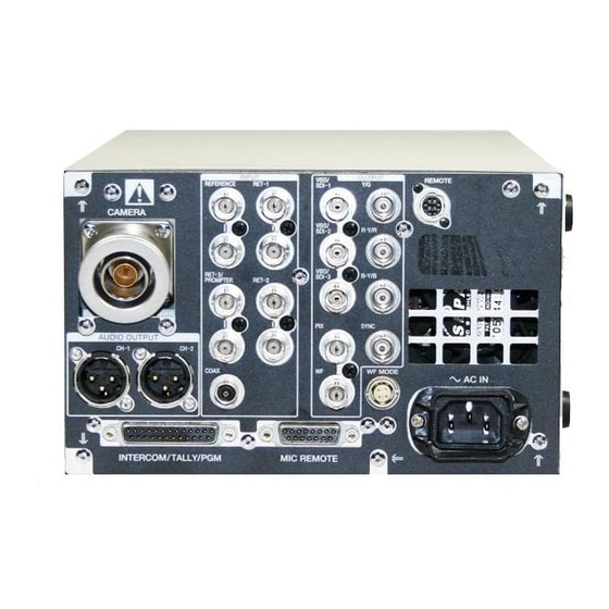
Page 13: Rear Panel
Rear panel a CAMERA connector b AUDIO OUTPUT connectors c INPUT connectors d OUTPUT connectors e REMOTE connector i AC IN connector h WF MODE connector g MIC REMOTE connector f INTERCOM/TALLY/PGM connector a CAMERA connector (triaxial connector) connector is terminated automatically with an Connects to the CA-TX50/50P Camera Adaptor impedance of 75 ohms. - Page 14 (BNC type) to be output. Accept return video signals from two different systems. For details on the internal boards, consult your nearest Sony dealer. For details on the selection of RET-1 and RET-2, refer to Operation Manual that came with the camera or camera C PIX (picture monitor output) connector (BNC adaptor.
- Page 15 AC IN (AC power input) connector Connects to an AC power source using the supplied AC power cord. Secure the power cord to the CCU-TX50/ 50P using the supplied plug holder. Function and Location of Parts and Controls...
-
Page 16: Connecting The Ccu-Tx50/50P To The Video Camera
Always turn the unit off first. Video camera Some switches or controls on the video camera may not work when the camera is connected to the CCU-TX50/ 50P. For details, refer to Operation Manuals of the video camera and the camera adaptor. -
Page 17: Self-Diagnostics
Settings of the Camera Self-Diagnostics The settings and operations status of the camera are displayed. The unit allows you to display the status of the unit and the results of a self-diagnosis is of the internal boards of the unit on the screen of a picture monitor connected to the unit. -
Page 18: Results Of The Self-Diagnosis Of The Internal Boards Of The Unit
Page 2 CCU-TX50: Model name and format of the camera control unit connected. Genlock: External reference signal and its status (lock/unlock) Prompter: Transmission direction of the prompter line Return 1 to 3: Return video signal input status Self-diagnostics of the Camera... - Page 19 AT board Each time you press the CHARACTER button, another page of results is displayed in turn. DM board Reference: Operation mode of the phase adjustment Gen Lock: Locking status BATT Volt: Voltage of the coin battery supplied with CAM Video: Reception status of the video signals the AT board from the camera.
-
Page 20: Diagnostics Page Of The Camera
IV board Diagnostics Page of the Camera Return: Setting status of the return signal input The results of the diagnosis of each board of the camera connectors to the return channels from 1 to 3 are displayed. Return Signal: Status of the return video input signal Rear CN: Power supply status of the CN board on the rear Exiting the Self-diagnostic Mode... -
Page 21: Notes On Use
VBS 1/2/3 BNC type (1 each) VBS, 1.0 Vp-p, 75 ohms BNC type (3) SDI format, 270 Mbps, SMPTE 259M (CCU-TX50)/CCIR656-III (CCU- TX50P) Y/R-Y/B-Y video BNC type (1 each) Y: 1.0 Vp-p, 75 ohms R-Y/B-Y: U.S.A. and Canada:... -
Page 22: Camera Input/Output Signals
PAL: 700 mVp-p, 75 ohms Encoded output: 1.0 Vp-p, 75 ohms WF MODE 4-pin (1) AUDIO OUTPUT XLR, 3-pin 0 dBu/–20 dBu, balanced, 2 channels SYNC BNC type 2) R/G/B/and Y/R-Y/B-Y are switchable. Camera input/output signals CAMERA Triax (Kings type for the U.S.A. and Canada, Fischer type for Europe) COAX BNC type (1), 75 ohms... - Page 25 Sony Corporation Printed in Belguim...
- Page 26 Color Video Camera Operating Instructions Before operating the unit, please read this manual thoroughly and retain it for future reference. DXC-D50K/D50PK DXC-D50L/D50PL DXC-D50WSL/D50WSPL DXC-D50H/D50PH DXC-D50WSH 2004 by Sony Corporation...
- Page 27 The model and serial numbers are located on the top. Record these numbers in the spaces provided below. Refer VARNING to them whenever you call upon your Sony dealer regarding Explosionsfare vid felaktigt batteribyte. this product. Använd samma batterityp eller en ekvivalent typ som rekommenderas av apparattillverkaren.
- Page 28 For customers in the USA For the customers in the USA and Canada This equipment has been tested and found to comply with the limits for a Class A digital device, pursuant to Part 15 of the RECYCLING NICKEL-CADMIUM BATTERIES FCC Rules.
- Page 29 Table of Contents Table of Contents Chapter 1 Overview Product Configurations ............ 7 Features ................9 Features on the DXC-D50/D50P/D50WS/D50WSP ..9 Features on the DXC-D50WS/D50WSP ......11 Location and Function of Parts ........12 Camera Head ..............12 VCL-920BY Zoom Lens ........... 18 DXF-801/801CE Viewfinder ..........
- Page 30 Chapter 3 Shooting Basic Procedure for Shooting ........43 Shooting with the DSR-1/1P ........... 46 Using the Edit Search Function While Back Space Editing ................46 Shuttle shot function ............47 Chapter 4 Viewfinder Screen Viewfinder Screen Indications ........49 Indications and Changing the Viewfinder Display ........
- Page 31 Table of Contents Chapter 5 Adjustments and White Balance Adjustment ..........77 Settings Saving an Appropriate White Balance Value in Memory ................ 77 Using the Preset White Balance Settings ......79 Light Sources and Color Temperature....... 80 Using the ATW (Auto Tracing White Balance) Function................
-
Page 32: Product Configurations
Chapter Overview Product Configurations The nine models, DXC-D50K, DXC-D50L/D50WSL, NTSC and PAL versions and the components as DXC-D50H, DXC-D50PK, DXC-D50PL/D50WSPL, shown in the figure on next page. The operation of the DXC-D50PH, and DXC-D50WSH, comprise both basic camera unit is the same in all cases. Chapter 1 Overview... - Page 33 Product Configurations DXC-D50K/D50PK DXC-D50L/D50PL/ D50WSL/D50WSPL Microphone VCT-U14 DXF-801/801CE Tripod Adaptor Viewfinder DXC-D50H/D50PH/D50WSH Test chart for flange focal length adjustment VCL-920BY DXC-D50/D50P/D50WS/D50WSP Zoom Lens Camera Head Camera adaptor The product kit does not include a camera adaptor: to use a camera adaptor, you will need to purchase a model CA-D50/D50P or CA-TX50/TX50P.
-
Page 34: Features
Features Variety of detail corrections Features on the DXC-D50/D50P/ • Skin detail function: this function gives a slightly D50WS/D50WSP softer appearance to the subject’s face. The target skin color can be easily set with the Menu operation. The DXC-D50WS/S50WSP is a 16:9 wide-screen type •... - Page 35 2 indicates the levels of 50 IRE or more for DSR-570WS/570WSP. For use with the Dynafit Pad, the DXC-D50/D50WS (or the levels of 50% or more consult your Sony dealer. for the DXC-D50P/D50WSP). Slide cover Video monitor output with text...
-
Page 36: Features On The Dxc-D50Ws/D50Wsp
High-performance viewfinder (DXF-801/ Features on the DXC-D50WS/ 801CE) D50WSP • High resolution (600 TV lines of horizontal Features only on the DXC-D50WS/D50WSP is resolution) described in this section. See “Features on the DXC- • Large-diameter eye cup for easier viewing and D50/D50P/D50WS/D50WSP”... -
Page 37: Location And Function Of Parts
Location and Function of Parts Camera Head Before attaching/detaching peripheral equipment to/ from the camera head, be sure to turn off the camera. Otherwise, the camera may not function properly. Right side view 1 5600K button 2 EDIT SEARCH buttons 3 A.IRIS MODE switch and indicator 4 EZ MODE button and indicator FOCUS... - Page 38 1 5600K button Note When this button is pressed (lit,) the standard color If the “easy focus” function is still on when you press temperature for shooting is switched to 5600K. Use the VTR button, it turns off automatically and this button for outdoor shooting in daytime or shooting recording starts.
- Page 39 Location and Function of Parts qs OUTPUT/DCC (Color bar output/dynamic contrast control) switch Use this switch to select the DCC function or color bar output. Select the CAM/ON position in most cases. CAM/ON: This activates the DCC function. This prevents color faults when shooting high-intensity subjects.
- Page 40 Front view 1 MIC IN +48 V connector 2 VF connector 3 FILTER control 4 Lens mount 5 SHUTTER switch 6 WHT/BLK switch 7 AUDIO LEVEL knob 8 VTR button 1 MIC (microphone) IN +48 V connector (XLR 3- 5 SHUTTER switch pin, female) Use this switch to turn the shutter on/off, or set the Connect the supplied microphone or an optional...
- Page 41 Location and Function of Parts Left and upper view 1 Fitting for optional microphone holder 2 Accessory fitting shoe and screw hole 3 Shoulder strap fixture 4 Viewfinder front-to-back position locking lever 5 Viewfinder fitting shoe 6 Viewfinder left-to-right position fixing ring 7 Viewfinder front-to-back position locking knob 8 MONITOR OUT connector 9 VIDEO OUT connector...
- Page 42 0 LENS connector (12-pin, for -inch lens) Connect the lens connector. qa REMOTE connector (10-pin) Connect the optional RM-M7G Remote Control Unit, or the RCP-TX7 or RCP-D50/D51 Remote Control Panel to this connector. Set the CAMERA HEAD SELECT switch on the bottom of RM-M7G to 1.
-
Page 43: Vcl-920By Zoom Lens
Location and Function of Parts VCL-920BY Zoom Lens 1 Focus ring 2 Zoom ring 3 Aperture ring 4 M button 5 F.B adjustment ring and F.B fixing knob 6 MACRO ring 7 ZOOM selector 8 Zoom remote control connector 9 VTR button 0 Shtl button qa DIP switch qs RET button... - Page 44 (Starting and stopping recording is controlled on Use this to adjust the aperture gain. Usually the the VTR.) trimmer is covered by a rubber cap. When operating with a CCU-TX50/TX50P Camera qj Shuttle memory position setting knob Control Unit connected: pressing this button Use this button for the shuttle shot function.
-
Page 45: Dxf-801/801Ce Viewfinder
Location and Function of Parts DXF-801/801CE Viewfinder You can switch the scan size of the DXF-801/801CE in accordance with the aspect ratio selected on the camera or camcorder. 4 TAKE/TALLY indicator TALLY TAKE BATT 5 BATT indicator 6 REC/TALLY indicators 1 Eyepiece focusing knob 7 GAIN UP indicator SHUTTER... - Page 46 6 REC/TALLY (recording/tally) indicators (red) qg DISPLAY switch • This flashes from the time when you press the VTR Set this switch to OFF when you want to remove the button (8 on page 15 and 9 on page 19) on the lens character data from the viewfinder and the monitor or camcorder until recording starts, then stays on connected to the MONITOR OUT connector.
-
Page 48: Replacing The Lithium Battery
(see page 84). • Use only CR2032-type lithium batteries. Other types of lithium batteries may come loose when the camcorder is moved. If you have difficulty finding CR2032-type lithium batteries, contact your Sony dealer. Chapter 2 Fitting and Connections... - Page 49 Replacing the Lithium Battery Open the battery cover (on the rear of the camera head). Pull the catch of the cover toward you while pushing it downward. Rear of the camera head For detaching the VTR or camera adaptor, see “Fitting a VTR” on the next page.
-
Page 50: Fitting A Vtr
Fitting a VTR This section explains how to attach the DSR-1/1P to When replacing the camera head grip with a camcorder grip, see “Using the Camcorder Grip” (page 26). the camera head. The method for attaching a PVV-3/ 3P is similar. Set the PRO 76-pin DIGITAL VTR (DSR-1/1P) connector on the DSR-1/1P. -
Page 51: Using The Camcorder Grip
Fitting a VTR Using the Camcorder Grip When using the camera head with a VTR as a camcorder grip and the method for attaching it differ camcorder, you can replace the camera head’s grip slightly depending on the type of VTR. with a camcorder grip (not supplied). - Page 52 Perform the first three steps in “Fitting a VTR”. Screw the connection plate (supplied with the grip for the DVCAM camcorder) which straddles the connection between the camera head and the DSR-1/1P. Also, tighten Connection the two screws in the shoulder plate pad section.
- Page 53 Fitting a VTR Remove the grip’s three screws, then pull up the grip to remove it. Remove the PVV-3/3P’s shoulder strap fitting. Shoulder strap fitting Attach the cover using the Grip for the Betacam camcorder screw supplied with the CAC- H102, then screw in to attach the grip for the Betacam camcorder.
-
Page 54: Fitting The Lens
Fitting the Lens In the case of the DXC-D50K/D50PK model, the lens is already fitted. In other cases, use the following procedure to fit the lens. Remove the retaining rubber which prevents the lens mount from coming loose, then raise Retaining rubber the lens fixing lever, and remove the lens mount cap. - Page 55 Fitting the Lens Using the triangular mark as a guide, push the lens connector into the LENS connector on the camera head, until it clicks into place. Fasten the cable with the clamps. Triangular mark LENS connector Fitting optional filters Loosen the lens hood fixing screw to remove the lens hood, then attach the filter.
-
Page 56: Using Accessories
Using Accessories Using the Viewfinder Removing the Viewfinder Remove any microphone from the viewfinder before beginning. VF connector Pull the viewfinder connector out of the VF connector on the front of the camera head. Loosen the viewfinder left-to- Retaining catch right position fixing ring, then Viewfinder left-to-right position fixing ring... -
Page 57: Using An Optional Microphone
You cannot stow the camera attached with a left eye with your left eye to the viewfinder. adaptor in the LC-HB330 Carrying Case. For details, consult your Sony dealer. Using an Optional Microphone To use a long microphone such as the optional ECM-... -
Page 58: Fitting To A Tripod
Fitting optional microphones (operable with a Note +48 V supply) other than the ECM-670 After removing the camera, if the tripod adaptor pin Use the same fitting procedure as for the ECM-670, has not returned to its original position, hold down the but note the following differences with respect to the red button and move the lever in the direction of the microphone adaptor. -
Page 59: Using The Lc-Hb330 Carrying Case
Using Accessories Using the LC-HB330 Carrying Case Example of fully-stowed carrying case The DXC-D50/D50P/D50WS/D50WSP Color Video Note Camera can be stored with the following system Be sure to read the Operating Instructions supplied component fitted. with the LC-HB330 Carrying Case before using. •... -
Page 60: Connections
Example: Connecting a BVW-50/50P Portable VTR to a CA-D50/D50P Camera Adaptor For details, consult your Sony dealer. CA-D50/D50P Camera Adaptor Notes • When using the CCU-TX50/TX50P Camera Control CCU/VTR/CMA Unit, use the PRO 76 PIN (DIGITAL) connector of 26-pin connector the CA-TX50/TX50P Camera Adaptor. DXC-D50/D50P/ •... - Page 61 ConnectionsCCU-D50/D50P DXF-51 DXC-D50/D50P/ Prompter video signal D50WS/D50WSP CA-D50/D50P Return video signal Headset Reference sync signal RM-M7G RCP-D50/D51 Camera Remote Remote Control Control Unit Panel INTERCOM CCU-D50/D50P Camera Control Unit (on the front) Headset VTR, chroma keyer, etc. to AC power supply DXF-51 DXC-D50/D50P/ D50WS/D50WSP...
-
Page 62: Connecting A Number Of Cameras (Without Using A Camera Control Unit)
Connecting a Number of Cameras (Without Using a Camera Control Unit) signal. The camera will then operate synchronized to When using two or more synchronized cameras this signal. without a camera control unit, connect an external sync You can adjust the synchronization using the signal to the GEN LOCK IN connector on the camera MAINTENANCE menus. -
Page 63: Power Supply
Intelligent Battery System and Ultralight System. hot, it may not be possible to obtain a full charge. For details, consult your Anton Bauer products supplier or Sony dealer. Battery pack operating times The following table shows approximate continuous operating times, when operating the camera and 1.5- type viewfinder at normal temperatures, with a camera adaptor and the DSR-1/1P or PVV-3/3P connected. -
Page 64: Camera Adaptor Power Supply
Battery pack charging Camera Adaptor Power Supply Before using a battery pack, charge it as shown in the The camera adaptor automatically operates on power following table. supplied to the CCU/VTR/CMA connector from the portable VTR, CCU-D50/D50P Camera Control Unit, For details of battery charger operation, refer to the CMA-8A/8ACE AC Adaptor or other connected instructions provided with the battery charger to be used. -
Page 65: Memory Stick
Memory Stick Types of Memory Stick Using a Memory Stick There are two types of Memory Stick: MagicGate When an optional Memory Stick is inserted into the Memory Stick that are equipped with the MagicGate camera, file data can be stored in the Memory Stick, copyright protection technology and general Memory which enables you to share data among several Stick. - Page 66 Memory Stick. This may damage the data. • Memory Stick and are the trademarks of Sony Corporation. • MagicGate Memory Stick and are the trademarks of Sony Corporation. Chapter 2 Fitting and Connections...
-
Page 68: Basic Procedure For Shooting
Chapter Shooting Basic Procedure for Shooting 5600K button ZEBRA switch RET button POWER switch Focusing ring FILTER control VTR button Attach the VTR or camera adaptor to the camera Set the FILTER control and the 5600K button head, then turn each device’s power on. appropriately for the lighting conditions. - Page 69 Basic Procedure for Shooting FILTER control settings If required, switch on the center marker and/or safety zone (OPERATION menu page 5) and zebra Filter setting Lighting conditions pattern (ZEBRA switch) in the viewfinder image. 1 (CLEAR) Indoor shooting Outdoor in cloudy or rainy day. Adjust the white balance (page 77) and black Indoor shooting and you wish to reduce balance (page 81).
- Page 70 Reviewing the recording It is possible to review the last few seconds of the recording on the tape (recording review). Press the VTR button to pause recording, then press the RET button on the lens. Depending on how long the button is pressed, the tape is automatically rewound over the last two to ten seconds from the paused position, and then this part is played back in the viewfinder.
-
Page 71: Shooting With The Dsr-1/1P
Shooting with the DSR-1/1P The DXC-D50/D50P/D50WS/D50WSP docks with Note the DSR-1/1P to configure a DVCAM digital Do not shut off the camera head’s power while camcorder. using the edit search function. The DSR-1/1P may The following describes how to shoot using a not be able to find the continue point. -
Page 72: Dip Switch Settings
While pressing the Shtl button, rotate the shuttle Shuttle shot function memory position knob 1 to set the zoom position. Rotate the knob to the T side to move in the telephoto What is the shuttle shot function? direction, and rotate to the W side to move in the wide- The shuttle shot function allows you to zoom at angle direction. -
Page 74: Viewfinder Screen Indications
Chapter Viewfinder Screen Indications and Menus Viewfinder Screen Indications There are four types of indication screen which appear Changing the Viewfinder Display in the viewfinder and the video monitor connected to the MONITOR OUT connector, as follows. Use the MENU switch and MENU dial shown in the •... - Page 75 Viewfinder Screen Indications Status indications PLAY TAPE NEAR END TCG 12:34:56:00 WHITE : 3200K A.IRIS : SPOT L. SCENE 01: ABCD1234 : ON BATT : 13.1V 03 08 01 5600K 12:34:56PM 64ND SKIN W:A 36dB 100.4H :::::::: 30-25 F5.6 Press the MENU switch toward the OFF/STATUS side.
- Page 76 Displaying the normal indications <USER PAGE 1> A.IRIS OVERRIDE DTL LEVEL To display the normal indications, set the POWER MASTER BLACK switch to the ON position. PRESET MATRIX : STD SCREEN MODE : 16:9 PLAY TAPE NEAR END TCG 12:34:56:00 Displaying the TOP MENU 03 08 01 5600K...
-
Page 77: Viewfinder Normal Indications
Whether or not to display can be selected by menu setting. d) This is recorded over the picture being shot. e) Displayed only when a CA-TX50/TX50P or CCU-TX50/TX50P is connected The significance of each of the indications shown in... - Page 78 16ND RET1, RET2, or RET3 indicates pressing the return 64ND video button on the CA-TX50/50P when the CA- TX50/50P and CCU-TX50/50P are connected. 9 SKIN DTL indication This appears when the skin detail function is activated. 4 Time data indication (See page 66.)
- Page 79 Viewfinder Normal Indications qd Audio recording level indicators These show the recording levels of audio channels 1 and 2 on the VTR. Channel 1 Channel 2 PVV-3/3P –20 dB +3 dB 0 dB ∞ DSR-1/1P – 0 dB –2 dB qf Tape remaining indication This shows the tape remaining in the VTR as follows.
-
Page 80: Menu Operation
Menu Operation To perform menu operations, first display the menu on Displaying the TOP MENU the viewfinder screen or the monitor connected via the MONITOR OUT connector. There are six menus: The TOP MENU can be displayed in either of the USER, USER MENU CUSTOMIZE, OPERATION, following ways: PAINT, MAINTENANCE, and FILE. -
Page 81: Setting The Menus
Menu Operation The question mark changes to an arrow, and the selected menu page is displayed. Setting the Menus Display the menu page on which you wish to make settings, then proceed in the following manner: Turn the MENU dial to move the arrow to your desired item, then press the MENU dial. -
Page 82: User Menu
USER Menu The USER menu consists of five pages (factory <USER PAGE 1> setting), on which frequently used items of the A.IRIS OVERRIDE OPERATION, PAINT, MAINTENANCE, and FILE DTL LEVEL MASTER BLACK menus are assigned. You can change the assigned PRESET MATRIX : STD items using the USER MENU CUSTOMIZE menu. -
Page 83: Using The User Menu
Menu Operation Using the USER Menu SELECT You can select desired pages from among the MOVE DELETE OPERATION, PAINT, MAINTENANCE and FILE menu pages and copy and set them on the USER menu. If you register pages frequently used on the USER menu, you can easily call those pages and use them. - Page 84 To change the order of the pages Turn the MENU dial to select DELETE, then press the MENU dial. Display the TOP MENU. The menu page selected in Step 4 is deleted, and For details, see “ Displaying the TOP MENU” on the screen returns to the PAGE EDIT screen.
- Page 85 Menu Operation Turn the MENU dial to select the line for which 3) Turn the MENU dial to select the item to be the menu item is to be registered, then press the registered, then press the MENU dial. MENU dial. The screen returns to the USER P1 EDIT The operation select screen appears.
- Page 86 Press the MENU dial. The indication “USER MENU RESET” is displayed, and the settings on all USER PAGEs are reset to the factory-preset values. Displaying the USER menu The USER menu that has been registered as described above can be displayed and operated in the same manner as with other menus.
-
Page 87: Operation Menu
Menu Operation OPERATION Menu The OPERATION menu consists of 11 pages. To <SWITCH> display the OPERATION menu, first display the TOP GAIN MENU, turn the MENU dial to select OPERATION, 18dB then press the MENU dial. OUTPUT [DCC] : AUTO KNEE 5600K DIMMER : 5 For details on how to display the TOP MENU, see “Displaying the TOP MENU”... - Page 88 Submenu title Page Setting item: Selectable Remarks Initial value values <VF/MARKER> SAFETY ZONE: ON ON, OFF To turn the safety-zone display on/off 80%, 90% To select the size of the safety zone NORMAL NORMAL, To select if the safety zone is to change in ASPECT accordance with the aspect ratio ASPECT IND: OFF...
- Page 89 Menu Operation Submenu title Page Setting item: Selectable Remarks Initial value values <ZEBRA> ZEBRA MODE: 1&2 1, 2, 1&2 To select if one zebra pattern or two zebra patterns are to be displayed ZEBRA1 LEVEL: 75% 50 to 75 to 109 To adjust the display level of Zebra 1 WIDTH: 10% 0 to 10 to 30...
-
Page 90: Paint Menu
PAINT Menu The PAINT menu consists of 10 pages. To display the <SHUTTER> PAINT menu, first display the TOP MENU, turn the SHUTTER : 1/100 MENU dial to select PAINT, then press the MENU CLS FREQUENCY: 60.38H : OFF dial. For details on how to display the TOP MENU, see “Displaying the TOP MENU”... - Page 91 Menu Operation Submenu title Page Setting item: Selectable Remarks Initial value values <KNEE/WHITE CLIP> KNEE POINT: 0 –99 to 0 to 99 To adjust the knee point (not available when DCC is activated) KNEE SLOPE: 0 –99 to 0 to 99 To adjust the knee slope (not available when DCC is activated)
- Page 92 Submenu title Page Setting item: Selectable Remarks Initial value values <USER MATRIX> SATURATION: 0 –99 to 0 to 99 To adjust the color saturation (color intensity) of the whole picture HUE: 0 –99 to 0 to 99 To adjust the hue of the whole picture [-R] [-G] [-B] —...
-
Page 93: Maintenance Menu
Menu Operation MAINTENANCE Menu The MAINTENANCE menu consists of 6 pages. To <RESET> display the MAINTENANCE menu, first display the ALL MENU RESET TOP MENU, turn the MENU dial to select MAINTENANCE, then press the MENU dial. For details on how to display the TOP MENU, see “Displaying the TOP MENU”... - Page 94 To turn on and off the TALLY indicator in the viewfinder when the CALL button on the CA-TX50/ TX50P is pressed if the CA-TX50/TX50P and CCU-TX50/TX50P are connected. If the TALLY indicator is lit, it goes dark. CCU CALL: ON...
-
Page 95: File Menu
Menu Operation FILE Menu The FILE menu consists of 4 pages. To display the Using the scene files, data for specific shooting FILE menu, first display the TOP MENU, turn the conditions are stored in memory of this unit, and MENU dial to select FILE, then press the MENU dial. - Page 96 Submenu title Page Setting item: Selectable Remarks Initial value values <OPERATOR FILE> OPERATOR FILE — To write or read data for this camera (incl. settings of customized USER menu) to/from a Memory Stick READ (MStCAMERA) — To copy the data in the Memory Stick to the camera Note If any operator file data are stored in the camera, the data for menu settings are replaced by the data from...
-
Page 97: Storing And Retrieving A Scene File
Menu Operation Retrieving a scene file Storing and Retrieving a Scene File Display page F1 <SCENE FILE1> of the FILE menu. Storing a scene file For details, see “Displaying your desired menu” on page 55. <SCENE FILE1> WHITE:OK Turn the MENU dial to select the number PAGE 1/2 STORE corresponding to the desired scene file, then press... -
Page 98: Storing To And Retrieving From A Memory Stick
All scene files stored in the Memory Stick are Storing to and Retrieving from a written to the camera. If any scene file has already Memory Stick been stored in the camera, that is replaced with the data from the Memory Stick. A scene file or an operator file stored in the camera can be copied to and stored in the Memory Stick, and Storing the operator file... -
Page 99: Items Stored In A File
Menu Operation Items Stored in a File You can store the setting for each item set in menu item is to be stored and the factory setting value. operations in a scene file and/or an operator file. The ∗ : Stored in the corresponding file table below shows in which file the setting of each Function Selectable values Scene Opera- Factory... - Page 100 Function Selectable values Scene Opera- Factory file tor file setting ∗ VF Display ND — ∗ IRIS — ∗ White — ∗ 5600K — ∗ Gain — ∗ Shutter — ∗ Skin DTL — ∗ Audio — ∗ Tape Remain —...
-
Page 102: Adjustments And Settings
Chapter Adjustments and Settings White Balance Adjustment Adjusting the white balance ensures that as lighting Saving an Appropriate White conditions change white objects remain white in the Balance Value in Memory image and tones remain natural. The color of light emitted varies from one light source You can save two white balance values in separate to another, and as the lighting changes the apparent memories, A and B. - Page 103 White Balance Adjustment Area of white within this rectangle should be equivalent to at least 10% of Center of the screen the image area. approximately approximately 70% of the 70% of the height of the width of the image image Push the WHT/BLK switch in the WHT direction and release.
-
Page 104: Using The Preset White Balance Settings
TIME LIMIT the A or B position. This automatically sets the If AWB adjustment cannot be performed camera to the white balance adjustment saved in the on the second try, consult your Sony dealer. corresponding memory. AWB:BREAK This message is displayed when the... -
Page 105: Light Sources And Color Temperature
White Balance Adjustment Light Sources and Color Using the ATW (Auto Tracing Temperature White Balance) Function Adjustment of the white balance to match the light The ATW function continuously adjusts the white source is essential to ensure correct color rendering. balance automatically to adapt to changes in lighting The color of a light source is indicated as a color conditions. -
Page 106: Black Balance Adjustment
Close the lens, then perform the Auto ABB:NG Black Balance adjustment again. TIME LIMIT If ABB adjustment cannot be performed on the second try, consult your Sony ABB:EXECUTING dealer. REFERENCE READ G ABB:BREAK This message is displayed when the ABB... -
Page 107: Shutter Settings
Shutter Settings This section covers the settings for electronic shutter speed and CLS (clear scan ) function. The new value for the shutter speed or clear scan frequency setting remains set until changed, even when the camera is powered off. Shutter speeds There are six shutter speeds, from s (DXC-D50/... - Page 108 When using the CLS function Watching the monitor screen, adjust the frequency to give minimum interference. If there is a black band in the monitor image, reduce the frequency, and if there is a white band, increase the frequency. For details on CLS setting, see page P1 <SHUTTER> of the PAINT menu.
-
Page 109: Setting The Clock And Timestamping Recordings
Setting the Clock and Timestamping Recordings Use the page M3 <CLOCK>of the MAINTENANCE <CLOCK> menu to set the camera head’s internal clock and record the date and time. 2003/08/01 08:32:45 HOUR TYPE DATE TYPE Y/Mn/D Notes CLOCK IND BARS •If the following date/time setting procedure for the internal clock does not cause the date/time information to be displayed in the MAINTENANCE menu, it may be due to a worn-out lithium battery in... -
Page 110: Viewfinder Screen Adjustments
Using an optional part allows you to modify the adjustment range to –2 to +1 diopters or –0.5 to +3 diopters. For details, consult your Sony dealer........................................... 1) Diopter: A unit to indicate the degree of convergence or divergence of a bundle of rays. -
Page 111: Adjusting The Lens
Adjusting the Lens Flange Focal Length Adjustment It is necessary to adjust the flange focal length (the • When a lens is fitted for the first time distance from the lens flange to the plane of the image • After changing lenses along the optical axis) in the following cases. -
Page 112: Aperture Adjustments
Aperture Adjustments Aperture ring Instant automatic aperture button Aperture selector ZEBRA switch A.IRIS MODE switch To make the image clearer when shooting a There are three ways of adjusting the aperture: subject lit by a spotlight automatically, manually, and with the instant In the automatic aperture adjustment mode, set the automatic aperture adjustment function. -
Page 113: Adjusting The Aperture Sensitivity
9 - 16 More precise settings according to your lenses are possible for lens numbers 9-16, if necessary. For details, consult your Sony dealer. (No data setting at shipping) If using a lens not mentioned in the above You can see the aperture sensitivity trimmer when... -
Page 114: Macrophotography
Macrophotography Use the macro function when the subject is at a distance of less than about 90 cm (3 feet) (for the VCL-920BY) from the front of the lens. It is possible to shoot close-ups down to a distance of 10 mm (wide angle, f = 8.5 mm). -
Page 115: Settings For Special Cases
Settings for Special Cases Settings for special cases Shooting conditions Setting Effect The background is very bright, and the Set the A.IRIS MODE switch to BACK This lightens the foreground. subject is too dark. L., turning the indicator on. The subject is under a spotlight. Set the A.IRIS MODE switch to SPOT This prevents white burn-out in highlights L., turning the indicator on. -
Page 116: Appendix
In the event of operating problems • Locations subject to violent vibration If you should experience problems with the unit, contact your supplier or Sony service representative. • Close to radio or TV transmitters producing strong electromagnetic fields. Connection with peripheral equipment... -
Page 117: Phenomena Specific To Ccd Image Sensors
Important Notes on Operation Phenomena Specific to CCD Image Sensors The following phenomena that may appear in images are specific to CCD (Charge Coupled Device) image sensors. They do not indicate malfunctions. White flecks Although the CCD image sensors are produced with high-precision technologies, fine white flecks may be generated on the screen in rare cases, caused by cosmic rays, etc. -
Page 118: Warning Indications
(During other fault in the heads, disconnect the recording only) the recording power and consult your Sony system. dealer. — — SERVO The servo Recording Disconnect the power and lock has continues, but consult your Sony dealer. -
Page 119: Specifications
Specifications Sensitivity 2000 lux (f/11.0 standard, 3200 K) DXC-D50/D50P/D50WS/D50WSP Camera Gain levels Selectable –3 dB, 0 dB, 3 dB, 6 dB, Head 9 dB, 12 dB, 18 dB, 24 dB, 30 dB, 36 dB Imaging element Three-chip interline transfer CCD Video output Composite signal 980 (horizontal) ×... -
Page 120: Related Products
Related Products 82 mm dia., 0.75 mm pitch Mounting Sony -inch bayonet mount There is a range of Sony products available to meet Mass Approx. 1.3 kg (2 lb 14 oz) every conceivable video shooting requirement. For (including lens hood) - Page 121 Specifications Studio equipment CCU-D50/D50P/TX50/TX50P Camera Control Unit DXF-51 5-inch Viewfinder (monochrome) DR-100 Intercom Headset Cables and miscellaneous The suffix number on a cable part number indicates the length in meters: e.g. a CCZ-A2 is 2 meters long. (Approximate equivalents in feet: 2 m = 6 ft, 5 m = 16 ft, 10 m = 33 ft, 25 m = 82 ft, 50 m = 164 ft, 100 m = 328 ft) Camera cables with Z-type 26-pin connectors...
-
Page 122: Chart Of Optional Components And Accessories
Chart of Optional Components and Accessories EC-0.5C2 Microphone Cable ECM-670/672 and C-74 Microphone CAC-12 Microphone Holder CCU-TX50/TX50P Camera TLCS Control Unit DXF-51 5-inch Viewfinder CA-TX50/TX50P Camera Adaptor CCZ-A cable CCU-D50/D50P Camera Control Unit CCZ-A DVW-250/250P cable Digital Betacam Recorder CCZ-A... - Page 123 Sony Corporation Printed in Belgium...
- Page 124 Before operating the unit, please read this manual thoroughly and retain it for future reference. You can find the operating instructions in Japanese, English, French, German and Italian on the CD-ROM (packed together). For details on the manuals supplied, see “Using the CD-ROM Manual” on page 6. CA-TX50/50P © 2004 Sony Corporation...
- Page 125 WARNING AVERTISSEMENT To prevent fire or shock hazard, do not expose Afin d’éviter tout risque d’incendie ou the unit to rain or moisture. d’électrocution, n’exposez pas cet appareil à la pluie ou à l’humidité. To avoid electrical shock, do not open the cabinet.
- Page 126 WARNUNG AVVERTENZA Um Feuergefahr und die Gefahr eines Per evitare il pericolo di incendi o scosse elektrischen Schlages zu vermeiden, darf das elettriche, non esporre l’apparecchio alla Gerät weder Regen noch Feuchtigkeit pioggia o all’umidità. ausgesetzt werden. Per evitare il rischio di scosse elettriche, non Um einen elektrischen Schlag zu vermeiden, aprire l’apparecchio.
- Page 128 Table of Contents Overview ..............6 Using the CD-ROM Manual ......... 6 CD-ROM System Requirements ......6 Preparations ............6 Reading the Manual in the CD-ROM ....6 Location and Function of Parts ......8 Front and Right Side .......... 8 Switches and Knobs on the Rear ......
-
Page 129: Overview
* It is required to perform the internal adjustment to change the http://www.adobe.com/ teleprompter video signal transfer direction to input. Contact your Sony dealer for more information on changing the teleprompter video signal transfer direction. Reading the Manual in the CD-ROM To read the operating instructions contained in the CD-ROM disc, do the following. - Page 130 If you lose the CD-ROM disc or become unable to read its content, for example because of a hardware failure, contact a Sony service representative. • Intel and Pentium are registered trademarks of Intel Corporation or its subsidiaries in the United States and other countries.
-
Page 131: Location And Function Of Parts
Location and Function of Parts Front and Right Side Accessory Shoe Shoulder Strap fitting c CALL button a Camera connector (PRO 76-pin DIGITAL) b POWER switch a Camera connector (PRO 76-pin DIGITAL) control panel. This unit’s back tally indicator also lights Connects to the camera’s 76-pin connector. -
Page 132: Switches And Knobs On The Rear
CALL button on the camera control unit or remote control panel has been pressed. When the INCOM selector on the CCU-TX50/50P Camera Control Unit is in the PRIV position, the intercom operates only between the camera and the... - Page 133 camera control unit regardless of the PROD/ENG switch position. g PROGRAM knob Adjusts the program audio reception level. When using a DXC-D50 series camera, setting the MIC/ LEVEL switch i to OFF/FRONT will enable this knob to adjust the balance between the program audio and intercom audio levels.
-
Page 134: Connectors And Switches On The Rear And Left Side
An internal adjustment can be made to enable both sides AC Adaptor for AC power sources. of the headset to receive audio, with intercom audio on Contact your Sony dealer for more information on refitting the the left side and program audio on the right side. CCU connector. - Page 135 REAR/LINE: Transfers audio from a line output for teleprompter video signals. connected to this unit’s AUDIO IN (CH1/CH2) Contact your Sony dealer for further information on the connector to the camera control unit. internal adjustment to change the teleprompter video signal transfer direction.
-
Page 136: Mounting On Video Camera
Note Mounting on Video Turn the POWER switch off before mounting the unit on Camera the camera. Fit the projection on the bottom of this unit into the This unit is dockable with the DXC-D50 series digital slot on the camera. video camera. -
Page 137: Removing From The Camera
Tighten the two screws (M4 × 6) to fix the shoulder Notes on Use pad. Use and storage locations Avoid using or storing the unit in the following places: • Where it is subject to extremes of temperature (operating temperature: –10ºC to +45ºC (14ºF to 113ºF)). -
Page 138: Specifications
Power requirements * WRR-861 series UHF Portable tuner is not available in some areas. When supplied via the CCU connector: For details, contact your Sony dealer. 180 V DC When supplied via the DC IN connector: 12 V DC (10.5 to 17 V Design and specifications are subject to change without notice. - Page 139 Sony Corporation Printed in Belguim...
- Page 140 Remote Control Panel Operating Instructions RCP-D50/D51...
- Page 141 English For the customers in Europe WARNING This product with the CE marking complies with the EMC To prevent fire or shock hazard, do not expose the unit to Directive (89/336/EEC) issued by the Commission of the rain or moisture. European Community.
- Page 142 Table of Contents Overview ................57 Features ................57 Locations and Functions of Parts ......... 58 Operation Panel ..............58 Connector Panel ..............66 Mounting on a Console ..........67 Menu Configuration and Basic Menu Operations ..68 Basic Operating Procedure ..........68 Basic Configuration of Menu Display ......
-
Page 143: Overview
Overview The RCP-D50/D51 Remote Control Panel enables Confirmation of camera conditions and remote operation of the DXC-D50-series, DXC-D30/ operation status D35-series,or DXC-637-series Color Video Cameras. This unit’s LCD panel indicates camera conditions such as the optical filter position, value, and lens The RCP-D50 and RCP-D51 are completely identical extender setting. -
Page 144: Locations And Functions Of Parts
Locations and Functions of Parts Operation Panel 1 MASTER and SLAVE buttons qa ASSIGN button qs Power and output select buttons MASTER SLAVE ASSIGN CAM PW BARS CLOSE 2 PREVIEW button AUTO SETUP qd AUTO SETUP buttons 3 STANDARD button PREVIEW SKIN DTL LEVEL... - Page 145 1 MASTER and SLAVE buttons 5 WHITE (white balance manual adjustment) When adjusting the white balance of multiple cameras knobs in Master/Slave mode, designate the master camera or Used to manually adjust the white balance. the slave cameras. Press and light up the MASTER The left knob is for the R signal and the right knob for button to specify the connected camera for the master.
- Page 146 Locations and Functions of Parts 0 PANEL ACTIVE button C CLOSE button Press and light up the button to permit this panel to Press and light the button to close the iris. To release control the camera system (Panel active status). the close mode, press the button again so that it goes dark.
- Page 147 qf White balance control buttons PRESET WHITE PRESET: Press and light this button to retrieve the preset white balance of the camera. A (memory A): Press and light this button to retrieve the white balance stored in memory A of the camera.
- Page 148 (When a CCU is used, the camera picture with characters is not displayed). If no camera picture is displayed with the CCU-TX7 connected, consult your Sony dealer. 3 LCD/touch panel Normally displays the statuses (see page 69)
- Page 149 Iris/master black control block (RCP-D50) 3 IRIS/M.BLACK LINK button 4 IRIS/M.BLACK ACTIVE button 5 AUTO button 6 f-number display 7 EXT indicator IRIS/M.BLACK ACTIVE OPEN IRIS/M.BLACK 1 MASTER BLACK display LINK 8 SENS control knob MASTER SENS BLACK AUTO 2 MASTER BLACK RELATIVE 9 COARSE control knob button RELATIVE...
- Page 150 Locations and Functions of Parts 5 AUTO button qd IRIS RELATIVE (iris relative) button Press and light the button to automatically adjust the When the IRIS/M.BLACK ACTIVE button is lit, the iris according to the amount of input light. iris adjustment mode can be selected with this button. When this button is lit, the reference value for Press and light up the button for Relative mode or automatic iris adjustment can be set with the iris...
- Page 151 Iris/master black control block (RCP-D51) 4 IRIS RELATIVE button 5 IRIS/M.BLACK LINK button 1 MASTER BLACK display 6 f-number display 7 EXT indicator 2 MASTER BLACK control 8 SENS control knob MASTER 9 COARSE control knob BLACK RELATIVE IRIS/ SENS OPEN CLOSE COARSE...
-
Page 152: Connector Panel
Locations and Functions of Parts 8 SENS (sensitivity) control knob Connector Panel Used for manual iris adjustment in Absolute mode. This control is not operative when Relative mode is selected. 1 MONITOR connector See the table “Iris adjustment functions”on page 64. 2 CCU/CAMERA connector 9 COARSE control knob 3 EXT I/O connector... -
Page 153: Mounting On A Console
Mounting on a Console The RCP-D50/D51 can be mounted on a console as shown below:... -
Page 154: Menu Configuration And Basic Menu Operations
Menu Configuration and Basic Menu Operations The RCP-D50/D51 provides menu operations for When the selected menu is composed of various functions such as adjustments of system multiple pages equipment. With the menu that is composed of multiple pages such as Paint menu, press v or V to flip the pages. See “Initial display (Paint menu)”... -
Page 155: Basic Configuration Of Menu Display
Basic Configuration of Menu Display Status display When you do not select any menu or the signal from the camera, the LCD shows the following status display: On the status display, the set value of each item is only displayed. The The set values of the shutter and master gain setting is made with the Function are displayed. - Page 156 Menu Configuration and Basic Menu Operations Adjustment display (Paint menu) When you select an item on the initial display of the Paint menu, the lower half of the panel becomes the adjustment display for the selected item. Example: when you select “White” from the PAINT 1 initial display with the DXC-D50 series connected The name of the item selected on the initial display is displayed.
- Page 157 Function menu displays When you press and light the FUNCTION button of the menu operation block, the scene file operation menu display is obtained. When “Operation” is selected Example: with the DXC-D50 series connected The ND filter number being selected Filter Opera- Lens...
- Page 158 Menu Configuration and Basic Menu Operations Monitor output set display (Expansion menu) [Monitor Select] When you press on an adjustment display of the Paint menu, the upper half of the panel becomes the monitor output setting display. When the CCU-TX7 is connected, you can select the WF/PIX output signals.
-
Page 159: Menu Items With The Dxc-D50-Series Cameras
Menu Items with the DXC-D50-Series Cameras The “Control items” marked with are those assigned The items displayed differ according to whether the to the control knobs. The other items are operated on unit is in Advanced Setting mode or in Normal Setting the menu display. - Page 160 Menu Configuration and Basic Menu Operations Page Menu Submenu Control item Function Paint 2 Detail Detail 1 • Level To adjust the detail (contour correction) level • H/V Ratio To adjust the ratio of V (Vertical) detail to H (Horizontal) detail in detail correction.
- Page 161 Page Menu Submenu Control item Function Paint 4 White Clip • Master To adjust the amount of white clip (the highest white level). As the value becomes larger, the output level decreases. TLCS TLCS To turn the TLCS (total level control) function ON/OFF •...
- Page 162 Menu Configuration and Basic Menu Operations Function menu (with the DXC-D50 series) Menu Control item Function Operation Jump menu 1 To jump to the adjustment screen designated for Menu 1 in Menu Set (Default: White of Paint 1) Jump menu 2 To jump to the adjustment screen designated for Menu 2 in Menu Set (Default:Black of Paint 1) Jump menu 3 To jump to the adjustment screen designated for Menu 3 in Menu Set (Default: Flare of Paint 1)
- Page 163 OTHERS menu (with the DXC-D50 series) Menu 2ndary menu Submenu Control item Function Adjusting White Shading • R To adjust the V white shading (vertical variation of the white) of the R signal • G To adjust the V white shading of the G signal •...
- Page 164 Menu Configuration and Basic Menu Operations Menu 2ndary menu Submenu Control item Function RCP Config VR Setting M. Black VR (Only available for RCP-D50) To select the response rate of the (cont.) (cont.) MASTER BLACK knob (relative-value adjustment rates: 1/1, 1/2, and 1/4, where 1/1 is the quickest response position) Information To display the software version of the unit...
- Page 165 Menu 2ndary menu Submenu Control item Function RCP Config Security Status Panel Active Lock To set whether to use the Panel Active Lock function with a security (cont.) (cont.) (cont.) code or not. Disable: Not to use the Panel Active Lock function Enable: To use the Panel Active Lock function by specifying a new security code Enable (Engineer Code): To use the Panel Active Lock function...
-
Page 166: Menu Items With The Dxc-D30/D35-Series Cameras
Menu Configuration and Basic Menu Operations Menu Items with the DXC-D30/D35-Series Cameras The “Control items” marked with are those assigned The items displayed differ according to whether the to the control knobs. The other items are operated on unit is in Advanced Setting mode or in Normal Setting the menu display. - Page 167 Page Menu Submenu Control item Function Paint 2 Detail Detail 1 • Level To adjust the detail (contour correction) level • H/V Ratio To adjust the ratio of V (vertical) detail to H (horizontal) detail in detail correction. As the value becomes larger, the V detail ratio increases.
- Page 168 Menu Configuration and Basic Menu Operations Page Menu Submenu Control item Function Paint 2 Black STR Black • Level To adjust the black stretch level (cont.) Stretch 1 • Stretch Level/Point 1 To adjust the upper limit of the signal levels that activate the black stretch function •...
- Page 169 Page Menu Submenu Control item Function Paint 4 CLS/EVS TLCS To turn the TLCS (total level control) function ON/OFF (cont.) Shutter To turn the shutter function ON/OFF To turn the CLS (clear scan) function (which reduces noise on the horizontal scan lines when the monitor screen connected to a PC is shot) ON/OFF To turn the EVS mode (which reduces flicker by increasing the vertical resolutions) ON/OFF...
- Page 170 Menu Configuration and Basic Menu Operations Menu Submenu Control item Function Lens/Pan Option 1 To turn the option control function 1 ON/OFF Option 2 To turn the option control function 2 ON/OFF • Focus To adjust the focus • Zoom To adjust the zoom •...
- Page 171 Menu 2ndary menu Submenu Control item Function RCP Config RCP LED Bright • Switch To set the brightness of respective LEDs (cont.) Adjusting • Tally (cont.) • Other • Master To set the brightness of the all LEDs of the unit RE Setting BLACK/FLARE To select the function for the BLACK/FLARE knob...
- Page 172 Menu Configuration and Basic Menu Operations Menu 2ndary menu Submenu Control item Function RCP Config Security Engineer Mode To set whether to display “Status”, “Menu Set”, and “Code No.” or (cont.) not (With Engineer Mode ON, all operative menu items are displayed regardless of the Advance Mode setting.) Status Advance Mode...
-
Page 173: Menu Items With The Dxc-637-Series Cameras
Menu Items with the DXC-637-Series Cameras The “Control items” marked with are those assigned The items displayed differ according to whether the to the control knobs. The other items are operated on unit is in Advanced Setting mode or in Normal Setting the menu display. - Page 174 Menu Configuration and Basic Menu Operations Function menu (with the DXC-637 series) Menu Control item Function Operation Jump menu 1 To jump to the adjustment screen designated for Menu 1 in Menu Set (Default: White of Paint 1) Jump menu 2 To jump to the adjustment screen designated for Menu 2 in Menu Set (Default:Black of Paint 1) Jump menu 3 To jump to the adjustment screen designated for Menu 3 in Menu Set (Default: Flare of Paint 1)
- Page 175 OTHERS menu (with the DXC-637 series) Menu 2ndary menu Submenu Control item Function Camera Title ID Title IND To turn the title display ON/OFF while the camera is in Color Bars Config mode Clock IND Switching of the clock indication Cam: To always display the clock indication Off: No clock indication File...
- Page 176 Menu Configuration and Basic Menu Operations Menu 2ndary menu Submenu Control item Function RCP Config Comm Link Gain To turn ON/OFF command link operation (activation of several (cont.) cameras at the same time) of the gain Shutter To turn ON/OFF command link operation of shutter settings R/B White To turn ON/OFF command link operation of the white R/B adjustment...
-
Page 177: Initial Settings
Initial Settings Setting the Operating Conditions RCP Config. Menu Exit of the RCP-D50/D51 Adjusting Setting By using the RCP Config menu or LCD setting display, you can set the built-in clock of the RCP-D50/ Cable Camera Date Comp Setting Time D51 and adjust various conditions of the RCP-D50/ D51, such as the sound volume of the warning buzzer Secu-... -
Page 178: Adjusting The Buzzer Sound
Initial Settings To set the date: Adjusting the Buzzer Sound [Date] 1) Press and light A buzzer sounds on the RCP-D50/D51 when it receives call signal or a panel control is operated. Date Time Setting Exit When required, you may turn on/off the buzzer or adjust the sound volume. -
Page 179: Adjusting The Brightness Of The Leds
To turn on/off the buzzers independently lamps, including the master black indicator and Press the corresponding button. When it is lit, the f-number indicator buzzer is on. The master brightness can be adjusted with the [Call Buzzer] : For the buzzer sound when a call signal rightmost control knob (Master). -
Page 180: Adjusting The Brightness/Contrast Of The Lcd
Initial Settings Set the menu to Advanced Setting mode. Adjusting the Brightness/ 1) Press [Security] on the RCP Config menu. Contrast of the LCD 2) Press and highlight [Engineer Mode]. You can adjust the brightness and contrast of the The [Status], [Menu Set], and [Code No.] buttons display of the menu control block. -
Page 181: Specifying The Security Codes
If you enter an incorrect security code, the message Specifying the Security Codes “!!!Code No. NG!!!” is displayed. You can authorize specific persons to set the menu to When you enter the correct security code, the Engineer mode, to operate this panel, and to adjust the Security Code setting display is resumed with iris and master black by specifying a security code. - Page 182 Initial Settings The Security Code input display appears. Press B to display the second page and press [Enable $ENG Code%] [Disable] (Pressing registers the same security code as Engineer mode for Panel Active Lock.) The security code is disabled. Operate in the same manner as step 5 and step 6 in Changing a security code “Locking Engineer mode with a security code.”...
-
Page 183: File Operations
File Operations This unit can operate two types of files: scene files and The table below shows the setting items which can be setup files. registered as either of the files. Setting data of cameras can be registered as scene files or setup files and recalled as required. - Page 184 File Operations Setup file Scene file Setting item DXC-D30/D35 DXC-D30/D35 DXC-D50 DXC-637 series only series series series Gamma correction on/off Master gamma R/B gamma Master black gamma R/G/B black gamma Gamma initial gain Black stretch level Upper/lower limit value for black stretch Upper/lower limit value for black compress DynaLatitude effect Matrix adjustment ON/OFF...
-
Page 185: Operating Scene Files
If the scene file button corresponding to the Operating Scene Files memory cell in which you wish to store data is not displayed, press either the v or V button at the Scene files are stored in the memory of this unit (or of lower-right position. -
Page 186: Transferring Scene Files Between The Camera And A Memory Stick (With The Dxc-D50 Series)
File Operations Reading the scene files from a Memory Transferring Scene Files between Stick the camera and a Memory Stick (with the DXC-D50 Series) Proceed as follows: Insert the Memory Stick ( see page 105 When a DXC-D50-series camera is connected, the registered scene files can be stored as a data block and Operate in the same manner as when you stored can be read when required. -
Page 187: Operating Setup Files (For Dxc-D30/D35 Series Only)
Press [Store]. Operating Setup Files (for DXC- D30/D35 Series only) The current settings of the camera are stored as a setup file with the name entered in Step 4, and that Among the setting items listed in the table on pages 97 filename is displayed on the list. -
Page 188: Skin Detail Correction/Skin Matrix Adjustment (For Dxc-D30/D35/D50 Series Only)
Skin Detail Correction/Skin Matrix Adjustment (for DXC-D30/D35/D50 Series Only) The skin detail and skin matrix functions can adjust If you power off the unit or store the current detail level and matrix (saturation and hue) of a settings as a scene file while setting the detail level selected skin gate area (area designated by color to the minimum value, the skin detail function will range). -
Page 189: Multi-Camera Control
CCU to make a daisy chain of the CCUs. For more information about cables which can be used, On the cameras connected to the RCP units whose consult your Sony dealer. IRIS/M.BLACK LINK buttons light, the iris or master black adjustments are performed by the... -
Page 190: Operating Multiple Cameras From One Rcp Unit -Command Link
Multi-Camera Control • The command link adjustment of R/G/B flare Notes correction is available only with the DXC-D30/D35/ • While scene file transfer is in progress on a slave D50 series. unit, do not tranfer data from the master unit to the slave unit. -
Page 191: Memory Sticks
Memory Sticks Using a Memory Stick Notes on Memory Stick When a Memory Stick is inserted in the panel, the file On Memory Stick data can be stored on the Memory Stick, which enables you to share data among RCPs. Memory Stick is a new compact, portable and versatile IC recording medium with a data capacity that exceeds that of a floppy disk. - Page 192 Memory Stick, be sure to use Memory Sticks of a size that can be used with both the RCP-D50/D51 and the camera. Memory Stick and are the trademarks of Sony Corporation. MagicGate Memory Stick and are the trademarks of Sony Corporation.
-
Page 193: Specifications
Specifications General Power requirements 10.5 to 17 V DC Power consumption 4.5 W Cable length 50 m (164 feet) max. (when the CCA-7 cable is used) Operating temperature 5°C to 40°C (41°F to 104°F) Dimensions (w/h/d) RCP-D50: 102 × 354 × 126.5 mm ×... - Page 194 Printed in Belgium...