Table of Contents
Advertisement
Quick Links
Advertisement
Table of Contents

Related Manuals for MSI MS-9125


Summary of Contents for MSI MS-9125
- Page 1 E7501 Master Series MS-9125 (v1.X) SSI Mainboard Version 1.0 G52-S9125X1-G22...
-
Page 2: Fcc-A Radio Frequency Interference Statement
Shielded interface cables and A.C. power cord, if any, must be used in order to comply with the emission limits. VOIR LA NOTICE D’INSTALLATION AVANT DE RACCORDER AU RESEAU. Micro-Star International MS-9125 Tested to comply with FCC Standard For Home or Office Use... -
Page 3: Copyright Notice
Alternatively, please try the following help resources for further guidance. Visit the MSI website for FAQ, technical guide, BIOS updates, driver updates, and other information: http://www.msi.com.tw/ Contact our technical staff at: support@msi.com.tw... -
Page 4: Safety Instructions
Safety Instructions Always read the safety instructions carefully. Keep this User’s Manual for future reference. Keep this equipment away from humidity. Lay this equipment on a reliable flat surface before setting it up. The openings on the enclosure are for air convection hence protects the equipment from overheating. -
Page 5: Table Of Contents
Safety Instructions ..................iv Chapter 1. Getting Started ................ 1-1 Mainboard Specifications ..............1-2 Mainboard Layout ................1-7 MSI Special Features ................1-8 PC Alert™ III ................. 1-8 Chapter 2. Hardware Setup ............... 2-1 Quick Components Guide ..............2-2 Central Processing Unit: CPU .............. 2-3 CPU Installation Procedures for Socket 604 ........ - Page 6 USB Ports ..................2-12 Connectors ..................2-13 Floppy Disk Drive Connector: FDD ..........2-13 ATA100 Connector: PRI IDE ............2-14 ATA133 RAID Connectors: RAID IDE1, RAID IDE2 ....2-14 Fan Power Connectors: CPUFAN1/2, SYSFAN1/2/3 ....2-15 Front Panel Connector: JSSI ............2-16 Ultra320 SCSI Connector: SCSI 2 (Channel B) ......
- Page 7 Getting Help .................. 3-3 The Main Menu ................... 3-4 Standard CMOS Features ..............3-6 IPMI V1.5 BIOS Features ..............3-8 Advanced BIOS Features ..............3-10 Advanced Chipset Features ............... 3-16 Integrated Peripherals ................ 3-19 Power Management Setup ..............3-23 PNP/PCI Configurations ..............3-26 PC Health Status ................
-
Page 8: Chapter 1. Getting Started
Getting Started Chapter 1. Getting Started Getting Started Thank you for purchasing the E7501 Master LRS2 (MS- 9125 v1.X) SSI (Server System Infrastructure) mainboard. The E7501 Master LRS2 is a superior computer mainboard based on ® Intel E7500/E7501 & ICH3-S chipsets for optimal system efficiency. -
Page 9: Mainboard Specifications
MS-9125 SSI Mainboard Mainboard Specifications Target Segment Target in the entry-level and mid-range, front-end and general purpose server market segments. The second-generation of microprocessors using the Intel ® NetBurst™ microarchitecture. ® Supports Single/Dual Intel Xeon™ with 512KB L2 cache processors. - Page 10 Getting Started Memory Bus Feature Supports dual channel (144-bit wide) DDR200/266 memory interface. Each channel supports 3 DIMM slots. Supports six 184-pin DDR DIMM sockets up to 12GB. Supports ECC (x72) DDR200/266 DIMMs using 64MB, 128MB, 256MB, or 512MB DRAMs. I/O Feature 266 MB/s point-to-point connection for ICH3-Switch parity protection.
- Page 11 MS-9125 SSI Mainboard Network Intel ® 82546EB Gigabit Ethernet Controller - Provides 1000, 100, and 10Mb/s data rates, 64-bit/100MHz PCI-X bus. - Dual ports. Power Management Features Wake up on LAN (WOL), USB, PCI, Mouse. RTC alarm. Supports ACPI S1, S4, and S5 functions.
- Page 12 SSI EEB 3.0 Form Factor: 12” x 13” (W x H). Mounting 18 mounting holes in total, including CPU fan mounting holes. MSI Reminds You... Enabling the functionality of Hyper-Threading Technology for your computer system requires ALL of the following platform Components: ®...
- Page 13 MS-9125 SSI Mainboard Table 1. 2D Modes (TFT or CRT) Mode Refresh Minimum Amount of Memory Required rate(Hz) 8bpp 16bpp 24bpp 32bpp 640x480 640X480 640X480 640X480 640X480 800X600 800X600 800X600 800X600 800X600 1024X768 1024X768 1024X768 1024X768 1024X768 1280x1024 1280x1024 1280x1024...
-
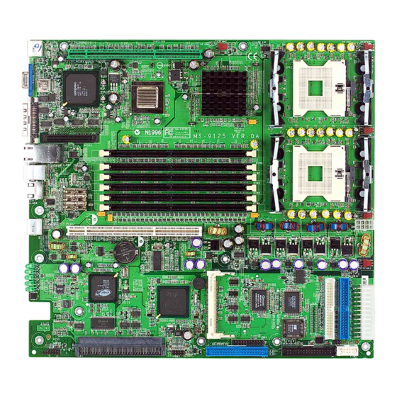
Page 14: Mainboard Layout
DIMM 3 DIMM 4 Intel DIMM 5 82546EB CPU1 DIMM 6 SYSFAN1 PCIX3 Port POWERJ2 BATT SYSFAN2 PCI1 RAGE XL Winbond Intel Promise W83627HF-AW 82801CA PDC20271 BIOS JBAT1 JSSI PRI IDE JLCD1 USB2 COM2 E7501 Master LRS2 (MS-9125 v1.X) SSI Mainboard... -
Page 15: Msi Special Features
MS-9125 SSI Mainboard MSI Special Features PC Alert™ III The PC Alert III is a utility you can find in the CD-ROM disk. The utility is just like your PC doctor that can de- tect the following PC hardware status during real time operation: monitor CPU &... -
Page 16: Chapter 2. Hardware Setup
Hardware Setup Chapter 2. Hardware Setup Hardware Setup This chapter provides you with the information about hard- ware setup procedures. While doing the installation, be careful in holding the components and follow the installation procedures. For some components, if you install in the wrong orientation, the components will not work properly. -
Page 17: Quick Components Guide
MS-9125 SSI Mainboard Quick Components Guide J27, p.2-25 SYSFAN3, p.2-15 CPU2, p.2-3 CPUFAN2, p.2-15 PCIX1, p.2-27 Back Panel I/O, p.2-9 CPUFAN1, S C S I 2 , p.2-15 p.2-17 DIMM1~6, CPU1, p.2-3 p.2-5 SYSFAN1, p.2-15 P C I X 3, POWERJ2, p.2-27... -
Page 18: Central Processing Unit: Cpu
Heat Sink and cooling fan, contact your dealer to purchase and install them before turning on the computer. MSI Reminds You... Overheating will seriously damage the CPU and system, always make sure the cooling fan can work properly to protect the CPU from overheating. -
Page 19: Cpu Installation Procedures For Socket 604
MS-9125 SSI Mainboard CPU Installation Procedures for Socket 604 1. Please turn off the power and Open Lever Sliding Plate unplug the power cord before installing the CPU. 2. Pull the lever sideways away from the socket. Make sure to raise the lever up to a 90- Dot / Cut Edge degree angle. -
Page 20: Memory
Hardware Setup Memory The mainboard provides 6 slots for 184-pin DDR SDRAM DIMM (Double In-Line Memory Module) modules and supports up to 12GB memory size. You can install PC2100/DDR266 or PC1600/DDR200 modules on the DDR DIMM slots (DIMM 1~6). DDR DIMM Slots (DIMM1/2/3/4/5/6) Memory Speed/CPU FSB Support Matrix DDR200... -
Page 21: Installing Ddr Modules
MS-9125 SSI Mainboard Memory modules can be installed in any combination as follows: Slot M em ory M od ule Population R u les Install Install (1) Install (1) Install (1) D IM M 1 D IM M 2 Install... -
Page 22: Power Supply
Hardware Setup Power Supply The mainboard supports SSI power supply for the power system. Be- fore inserting the power supply connector, always make sure that all compo- nents are installed properly to ensure that no damage will be caused. SSI 24-Pin Power Connector: POWERJ1 This connector allows you to connect an SSI power supply. -
Page 23: Ssi 8-Pin Power Connector: Powerj2
MS-9125 SSI Mainboard SSI 8-Pin Power Connector: POWERJ2 This connector is an optional power connector to provide 12V power output. SSI 5-Pin Power Connector: J9 This connector provides power supply to the System Management Bus (SMB). POWERJ2 J9 Pin Definition... -
Page 24: Back Panel
Hardware Setup Back Panel The back panel provides the following connectors: RJ-45/COM1 (with serial port converter) Mouse/ SCSI Keyboard (with Y-type PS/2 converter) Serial Port Connector: RJ-45/COM1 A serial port converter is provided in the mainboard package to convert the onboard RJ-45/COM1 port from the RJ-45 LAN jack into standard 9-pin serial port COM1. -
Page 25: Mouse/Keyboard Connector
MS-9125 SSI Mainboard Mouse/Keyboard Connector The mainboard provides a standard PS/2 ® mouse/keyboard mini DIN ® ® connector for attaching a PS/2 mouse/keyboard. You can plug a PS/2 mouse/ keyboard directly into this connector or use the provided Y-type PS/2 con- verter to simultaneously connect to a mouse &... -
Page 26: Rj-45 Lan Jack: Giga-Bit Lan
Hardware Setup RJ-45 LAN Jack: Giga-bit LAN The mainboard provides one standard RJ-45 jack for connection to Local Area Network (LAN). Giga-bit LAN enables data to be transferred at 1000, 100 or 10Mbps. Pin assignments vary depending on the transfer rates: 10/100Mbps or 1000Mbps. -
Page 27: Ultra320 Scsi Connector: Scsi 3 (Channel A)
MS-9125 SSI Mainboard Ultra320 SCSI Connector: SCSI 3 (Channel A) SCSI (Small Computer System Interface) is a parallel interface standard for attaching peripheral devices to computers. Ultra320 SCSI is the seventh generation of SCSI I/O technology, and has a maximum data rate speed of 320 MB/sec. -
Page 28: Connectors
Hardware Setup Connectors The mainboard provides connectors to connect FDD, IDE HDD, front panel of the system case, audio ports, USB Ports, and CPU/System FANs. Floppy Disk Drive Connector: FDD The mainboard provides a standard floppy disk drive connector that supports 360K, 720K, 1.2M, 1.44M and 2.88M floppy disk types. -
Page 29: Ata100 Connector: Pri Ide
MS-9125 SSI Mainboard ATA100 Connector: PRI IDE The mainboard offers one Ultra ATA/100 hard drive connector. ATA133 RAID Connectors: RAID IDE1, RAID IDE2 The mainboard supports high-end Ultra ATA/133 RAID (0, 1, or 0+1) hard drive interface specifications as well. -
Page 30: Fan Power Connectors: Cpufan1/2, Sysfan1/2/3
CPU fan control. SYSFAN3 CPUFAN2 +12V SENSOR +12V SENSOR CPUFAN1 +12V SENSOR SYSFAN1 +12V SENSOR SYSFAN2 MSI Reminds You... Always consult the vendors for proper CPU cooling fan. 2-15... -
Page 31: Front Panel Connector: Jssi
MS-9125 SSI Mainboard Front Panel Connector: JSSI The mainboard provides one front panel connector for electrical con- nection to the front panel switches and LEDs. Reset Power Power Switch Switch JSSI Standby Giga-bit SMBus Power (5V) LAN2 Giga-bit Chassis LAN1 LED... -
Page 32: Ultra320 Scsi Connector: Scsi 2 (Channel B)
Hardware Setup Ultra320 SCSI Connector: SCSI 2 (Channel B) SCSI (Small Computer System Interface) is a parallel interface standard for attaching peripheral devices to computers. Ultra320 SCSI is the seventh generation of SCSI I/O technology, and has a maximum data rate speed of 320 MB/sec. -
Page 33: Lcd Panel Connector: Jlcd1
MS-9125 SSI Mainboard LCD Panel Connector: JLCD1 The connector is additionally provided for connection to a LCD panel, which shows information on the panel for you to identify the current status or mode of the connected system. JLCD1 SIGNAL GND1... -
Page 34: Front Usb Connector: Usb2
Hardware Setup Front USB Connector: USB2 The mainboard provides one front Universal Serial Bus connector for users to connect to USB ports. Pin Definition Description Description USBPWR USBPWR USBP2- USBP3- USBP2+ USBP3+ USB2 Serial Port Connector: COM 2 The mainboard offers one 9-pin header as serial port COM 2. The port is a 16550A high speed communication port that sends/receives 16 bytes FIFOs. -
Page 35: System Id Led Connector: J30
System ID LED Connector: J30 The connector is used to connect the System ID LED on the front panel. Please note that this connector is specifically designed for MSI MS-9206 & MS-9214 rackmount servers only. System ID Button Connector: J38 The connector is used to connect the System ID Button on the front panel to facilitate system management. -
Page 36: System Id Button: J23
LED lights up, the server manager will immediately know that the remote subsystems are currently sharing certain services to his system. By pressing the J23 button again, the D81 LED will go out. Please note that this function is specifically designed for MSI MS-9206 & MS-9214 rackmount servers only. Front View... -
Page 37: Five-Fan Module Power Connector: Fan
MS-9125 SSI Mainboard Five-Fan Module Power Connector: FAN A module consisting of five 40mm, multi-speed fans provides the pri- mary airflow for the system. A 12-wire cable/connector provides the fan mod- ule with power and tach lines, allowing each fan to be monitored indepen- dently by server management software. -
Page 38: 6-Pin I2C Bus Connector: J34
Hardware Setup 6-pin I2C Bus Connector: J34 The mainboard provides one I2C (also known as I C) Bus connector for users to connect to System Management Bus (SMBus) interface. J34 Pin Definition SIGNAL SMBUS_SDA SMBUS_SCL 5VCC SMBUS_ALERT# PCIRST# 2-23... -
Page 39: Jumpers
MS-9125 SSI Mainboard Jumpers The motherboard provides the following jumpers for you to set the computer’s function. This section will explain how to change your motherboard’s function through the use of jumpers. Clear CMOS Jumper: JBAT1 There is a CMOS RAM on board that has a power supply from external battery to keep the data of system configuration. -
Page 40: Pcix Channel A Frequency Jumper: J27
Hardware Setup PCIX Channel A Frequency Jumper: J27 The jumper is used to set the channel A of 64-bit PCI bus (PCIX) to run at PCI 66 Mode or PCI-X Mode. Channel A includes SCSI interface and 64- bit PCIX1 slot. PCI 66 Mode PCI-X Mode PCIX Channel B Frequency Jumper: J28... -
Page 41: Vga Disable/Enable Jumper: J15
MS-9125 SSI Mainboard VGA Disable/Enable Jumper: J15 This jumper is used to enable or disable the onboard VGA. Disable VGA Enable VGA 2-26... -
Page 42: Slots
Hardware Setup Slots The motherboard provides two 64-bit Master PCI-X bus slots and one Mini PCI slot. 64-bit PCI-X Slot (ZCR) 64-bit PCI-X Slot Mini PCI Slot PCI (Peripheral Component Interconnect) Slots The PCI slots allow you to insert the expansion cards to meet your needs. When adding or removing expansion cards, make sure that you unplug the power supply first. -
Page 43: Mini Pci Bus
MS-9125 SSI Mainboard Mini PCI bus This bus is used to connect the optional MS-9518 SCSI card. MS-9518 SCSI card Mini PCI slot Installing the card: 1. Locate the Mini PCI slot on the mainboard. 2. Place the card over the Mini PCI slot... - Page 44 Hardware Setup 3. Locate the supporters on the mainboard (one on the right end and the other on the left end). supporters 4. Align the two fixing holes on the card with the supporters and press the card carefully down until the fixing holes get locked by the supporters.
- Page 45 MS-9125 SSI Mainboard Removing the card: 1. Gently push the retaining clips outwards. Hold the card lightly but firmly. Use long nose pliers to clip one of the supporters and press it down- wards until it withdraws from the fix- ing hole.
-
Page 46: Pci Interrupt Request Routing
Hardware Setup PCI Interrupt Request Routing The IRQ, acronym of interrupt request line and pronounced I-R-Q, are hardware lines over which devices can send interrupt signals to the microprocessor. The PCI IRQ pins are typically connected to the PCI bus INT A# ~ INT D# pins as follows: PCI-32 IRQ Routing (for ICH3) PCI Device... -
Page 47: Chapter 3. Bios Setup
BIOS Setup Chapter 3. BIOS Setup BIOS Setup This chapter provides information on the BIOS Setup pro- gram and allows you to configure the system for optimum use. You may need to run the Setup program when: An error message appears on the screen during the system booting up, and requests you to run SETUP. -
Page 48: Entering Setup
MS-9125 SSI Mainboard Entering Setup Power on the computer and the system will start POST (Power On Self Test) process. When the message below appears on the screen, press <DEL> key to enter Setup. Press DEL to enter SETUP If the message disappears before you respond and you still wish to enter Setup, restart the system by turning it OFF and On or pressing the RESET button. -
Page 49: Getting Help
Press <Esc> to exit the Help screen. MSI Reminds You... The items under each BIOS category described in this chapter are under continuous update for better system performance. -
Page 50: The Main Menu
MS-9125 SSI Mainboard The Main Menu Once you enter Phoenix-Award BIOS CMOS Setup Utility, the Main Menu will appear on the screen. The Main Menu displays thirteen configurable functions and two exit choices. Use arrow keys to move among the items and press <Enter>... - Page 51 BIOS Setup Power Management Setup Use this menu to specify your settings for power management. PNP/PCI Configurations This entry appears if your system supports PnP/PCI. PC Health Status (for mainboards without mBMC chip) This entry shows your PC health status. Frequency/Voltage Control Use this menu to specify your settings for frequency/voltage control.
-
Page 52: Standard Cmos Features
MS-9125 SSI Mainboard Standard CMOS Features The items inside Standard CMOS Features menu are divided into 10 categories. Each category includes none, one or more setup items. Use the arrow keys to highlight the item you want to modify and use the <PgUp> or <PgDn>... - Page 53 BIOS Setup your hard disk drive type is not matched or listed, you can use Manual to define your own drive type manually. If you select Manual, related information is asked to be entered to the follow- ing items. Enter the information directly from the keyboard. This information should be provided in the documentation from your hard disk vendor or the system manufacturer.
-
Page 54: Ipmi V1.5 Bios Features
MS-9125 SSI Mainboard IPMI V1.5 BIOS Features This setup screen appears only when the mBMC chip (for Server Management) is integrated on the mainboard. PEF Configuration Status This option shows the current Platform Event Filter (PEF) configuration status. (Read only) Setting PEF Configuration This setting is used to set the Platform Event Filter (PEF) configuration. - Page 55 BIOS Setup able on expiration of the Watchdog Timer: No Action, Hard Reset, Power Down, Power Cycle. WatchDog Timer Counter This feature allows users to set the time interval to reboot the computer if a timeout event occurs. Setting options: 10 Sec, 20 Sec, 30 Sec, 40 Sec.
-
Page 56: Advanced Bios Features
This setting is used to enable/disable the fan speed control function. Smart Fan Control This setting controls the Fan PWM Duty Cycle. When setting to MSI Def., the duty cycle will be controlled by BIOS. When setting to Auto, the duty cycle will be controlled by fans. - Page 57 Setting options: Enabled, Disabled. MSI Reminds You... Enabling the functionality of Hyper-Threading Technology for your computer system requires ALL of the following platform Components: ®...
- Page 58 MS-9125 SSI Mainboard Quick Power On Self Test The option speeds up Power On Self Test (POST) after you power on the computer. When setting the item to Enabled, BIOS will shorten or skip some check items during POST. Settings: Enabled, Disabled.
- Page 59 BIOS Setup Floppy Disk Access Control This enables or disables the write protection for floppy drive. Settings: R/W, Read Only. Boot Up NumLock Status This setting is to set the Num Lock status when the system is powered on. Setting to On will turn on the Num Lock key when the system is powered on. Setting to Off will allow users to use the arrow keys on the numeric keypad.
- Page 60 MS-9125 SSI Mainboard MPS Version Control For OS This field allows you to select which MPS (Multi-Processor Specification) version to be used for the operating system. You need to select the MPS ver- sion supported by your operating system. To find out which version to use, consult the vendor of your operating system.
- Page 61 BIOS Setup IRQ6 when the system contains no floppy drive. When this setting is set to Yes, users have to select Disabled for the Onboard FDC Controller in the Integrated Peripherals menu. Setting options: Yes, No. Small Logo(EPA) Show This setting enables you to show the EPA logo (brand specific graphics) on the bootup screen.
-
Page 62: Advanced Chipset Features
MS-9125 SSI Mainboard Advanced Chipset Features MSI Reminds You... Change these settings only if you are familiar with the chipset. DRAM Timing Control Press <Enter> to enter the following sub-menu screen. DRAM Timing Configure Selects whether DRAM timing is controlled by the SPD (Serial Presence Detect) EEPROM on the DRAM module. - Page 63 BIOS Setup figurations on the SPD. Selecting Manual allows users to configure these fields manually. --CAS Latency Time This controls the timing delay (in clock cycles) before SDRAM starts a read command after receiving it. Settings: 1.5, 2, 2.5 (clocks). 1.5 (clocks) increases the system performance the most while 2.5 (clocks) provides the most stable performance.
- Page 64 MS-9125 SSI Mainboard writes to this memory area, a system error may result. Setting options: Enabled, Disabled. Memory Hole At 15M-16M In order to improve performance, certain space in memory can be reserved for ISA peripherals. This memory must be mapped into the memory space below 16MB.
-
Page 65: Integrated Peripherals
BIOS Setup Integrated Peripherals OnChip IDE Device Press <Enter> to enter the following sub-menu screen. IDE HDD Block Mode This allows your hard disk controller to use the fast block mode to transfer data to and from the hard disk drive. Block mode is also called block transfer, multiple commands or multiple sector read/write. - Page 66 MS-9125 SSI Mainboard On-Chip Primary PCI IDE The integrated peripheral controller contains an IDE interface with sup- port for two IDE channels. Choose Enabled to activate each channel separately. IDE Primary Master/Slave PIO The four items allow you to set a PIO (Programmed Input/Output) mode for each of the four IDE devices that the onboard IDE interface supports.
- Page 67 BIOS Setup Onboard LAN The field determines whether the onboard Giga-bit LAN controller is activated. Setting options: Enabled, Disabled. Onboard SCSI The field determines whether the onboard SCSI controller is activated. Setting options: Enabled, Disabled. Onboard RAID Device This setting controls the onboard RAID device. Setting options: Enabled, Disabled.
- Page 68 MS-9125 SSI Mainboard the field for the PS/2 keyboard to power on the system. Please note that this function will only work under S3 mode. Hot Key Power ON If POWER ON Function is set to Hot KEY, you can assign a hot key com- bination in the field for the PS/2 keyboard to power on the system.
-
Page 69: Power Management Setup
BIOS Setup Power Management Setup MSI Reminds You... S3-related functions described in this section are available only when your BIOS supports S3 sleep mode. ACPI Function This item is to activate the ACPI (Advanced Configuration and Power Man- agement Interface) function. If your operating system is ACPI-aware, such as Windows 98SE/2000/ME, select Enabled. - Page 70 MS-9125 SSI Mainboard the vertical and horizontal synchronization ports and write blanks to the video buffer. Blank Screen This option only writes blanks to the video buffer. DPMS Initial display power management signaling. Video Off In Suspend This setting determines whether the monitor will be turned off during suspend mode.
- Page 71 The field specifies the time for Resume by Alarm. Format is <hour> <minute><second>. MSI Reminds You... If you have changed this setting, you must let the system boot up until it enters the operating system, before this function will work.
-
Page 72: Pnp/Pci Configurations
MS-9125 SSI Mainboard PNP/PCI Configurations This section describes configuring the PCI bus system and PnP (Plug & Play) feature. PCI, or Peripheral Component Interconnect, is a system which allows I/O devices to operate at speeds nearing the speed the CPU itself uses when communicating with its special components. - Page 73 BIOS Setup IRQ Resources The items are adjustable only when Resources Controlled By is set to Manual. Press <Enter> and you will enter the sub-menu of the items. IRQ Resources list IRQ 3/4/5/7/9/10/11/12/14/15 for users to set each IRQ a type depending on the type of device using the IRQ.
-
Page 74: Pc Health Status
MS-9125 SSI Mainboard PC Health Status This setup screen shows the status of your CPU, fan, overall system status,.. etc. Monitor function is available only if there is hardware monitor- ing mechanism onboard. Chassis Intrusion Detect The field enables or disables the feature of recording the chassis intrusion status and issuing a warning message if the chassis is once opened. -
Page 75: Frequency/Voltage Control
BIOS Setup Frequency/Voltage Control Use this menu to specify your settings for frequency/voltage control. CPU Clock Ratio This setting controls the multiplier that is used to determine the internal clock speed of the processor for overclocking purposes. Auto Detect DIMM/PCI Clk This item is used to auto detect the DIMM/PCI slots. -
Page 76: Load Fail-Safe/Optimized Defaults
MS-9125 SSI Mainboard Load Fail-Safe/Optimized Defaults The two options on the main menu allow users to restore all of the BIOS settings to the default Fail-Safe or Optimized values. The Optimized Defaults are the default values set by the mainboard manufacturer specifically for op- timal performance of the mainboard. -
Page 77: Set Supervisor/User Password
FEATURES menu. If the Security Option is set to System, the password is required both at boot and at entry to Setup. If set to Setup, password prompt only occurs when you try to enter Setup. MSI Reminds You... About Supervisor Password & User Password: Supervisor password: Can enter and change the settings of the setup menu. -
Page 78: Chapter 4. Scsi Bios Setup (Optional)
SCSI BIOS Setup Chapter 4. SCSI BIOS Setup (optional) SCSI BIOS Setup (Optional) This chapter provides information on the Small Computer System Interface (SCSI) BIOS setup utility and allows you to configure the SCSI subsystem for optimum use. You may need to run the SCSI BIOS setup utility when: You want to change the default SCSI controller settings for customized features. -
Page 79: Entering Scsi Bios
MS-9125 SSI Mainboard Entering SCSI BIOS Power on the computer and the system will start POST (Power On Self Test) process. When the message below appears on the screen, press <Ctrl> + <A> keys simultaneously to enter SCSI BIOS utility. - Page 80 SCSI BIOS Setup AIC-7902 A at slot 0A, 03:07:00 Would you like to configure the SCSI controller, or run the SCSI Disk Utilities? Select the option and press <Enter>. Options Configure/View SCSI Controller Settings SCSI Disk Utilities Configure/View SCSI Controller Settings Use this option for SCSI controller configurations.
-
Page 81: Configure/View Scsi Controller Settings
MS-9125 SSI Mainboard Configure/View SCSI Controller Settings There are 8 items in the “Configure/View SCSI Controller Settings” screen. These items display or allow you to change the SCSI controller’s settings. Use the arrow keys to highlight the item and then press <Enter> to select the value you want in each item or enter each item’s sub-menu screen. -
Page 82: Additional Options
SCSI BIOS Setup SCSI Controller Termination In order to have the SCSI bus function properly and reliably, termination at the ends of the SCSI bus is necessary. Proper termination can ensure signal on the SCSI bus will not reflect and cause data loss or errors. Settings options: Enabled, Disabled. - Page 83 MS-9125 SSI Mainboard SCSI Device Configuration SCSI Device ID Sync Transfer Rate (MB/Sec) ..320 320 320 320 320 320 320 320 Packetized......... Yes Yes Yes Yes Yes Yes Yes Yes QAS........... Yes Yes Yes Yes Yes Yes Yes Yes Initiate Wide Negotiation ....
- Page 84 SCSI BIOS Setup SCSI device to disconnect during an I/O transfer operation. The discon- nection ability frees the SCSI bus to allow other I/O processes and thus optimizes the SCSI bus performance. Setting options: Yes, No. Send Start Unit Command When set to Yes, the SCSI controller sends the Start Unit command to the specified SCSI device during bootup.
- Page 85 MS-9125 SSI Mainboard Display <Ctrl><A> Message During BIOS Initialization When enabled, the message “Press <Ctrl><A> for SCSISelect(TM) Util- ity” appears on the screen during bootup. If disabled, the message does not show up, but you can still press <Ctrl> + <A> key combination to enter the SCSI BIOS utility.
-
Page 86: Bios Information
SCSI BIOS Setup device, make sure no bootable CD-ROM is inserted or disable this option. BIOS Information Interrupt (IRQ) Channel Displays the IRQ line assigned to the SCSI channel. I/O Port Address Displays the I/O port address assigned to the SCSI channel. -
Page 87: Disk Utilities
MS-9125 SSI Mainboard Disk Utilities AIC-7902 A at slot 0A, 03:07:00 Select SCSI Disk and press <Enter> SCSI ID#0: No device SCSI ID#1: No device SCSI ID#2: No device SCSI ID#3: No device SCSI ID#4: No device SCSI ID#5: No device... - Page 88 SCSI BIOS Setup Select the SCSI device which you want to manage by highlighting the item and press <Enter>. The following dialog box appears. Select the function you want to perform. SCSI ID# 0: HITACHI DK32DJ-18MW Firmware: G2G2 Capacity: 17GB Format Disk Verify Disk Media Format Disk...
-
Page 89: Troubleshooting
Q: How do I know what MSI D-LED or D-bracket light mean? A: Please follow the special tech issue, http://www.msi.com.tw/support/ techexpress/special_tech/smartled.htm Q: I used my MSI motherboard and got an error message, "Primary IDE Channel No 80 Conductor Cable Installed" while the system detected hard drives. - Page 90 2. Try to clear the CMOS If problem still persists, ask your reseller for new BIOS chip or contact one of MSI office near your place for new BIOS chip http:// www.msi.com.tw/contact/main.htm Q: Should I update my BIOS, once a new BIOS is released? A: A new BIOS is usually released due to the following reasons: 1.
- Page 91 BIOS, unless you really have to. Q: How do I update the BIOS? A: Please refer to http://www.msi.com.tw/support/bios/note.htm for details. Q: How do I identify the BIOS version? A: Upon boot-up, the 1st line appearing after the memory count is the BIOS version.
- Page 92 MS-9125 SSI Mainboard Q: After I flashed the BIOS and rebooted the system, the screen went blank. A: For AMI BIOS Rename the desired AMI BIOS file to AMIBOOT.ROM and save it on a floppy disk. e.g. Rename A569MS23.ROM to AMIBOOT.ROM Insert this floppy disk in the floppy drive.
-
Page 93: Glossary
Glossary Glossary Glossary ACPI (Advanced Configuration & Power Interface) This power management specification enables the OS (operating system) to control the amount of power given to each device attached to the computer. Windows 98/98SE, Windows 2000 and Windows ME can fully support ACPI to allow users managing the system power flexibly. - Page 94 MS-9125 SSI Mainboard contents of frequently accessed RAM locations and the addresses where these data items are stored. Chipset A collection of integrated chips designed to perform one or more related functions. For example, a modem chipset contains all the primary circuits for transmitting and receiv- ing data;...
- Page 95 Glossary ECC Memory (Error Correcting Code Memory) A type of memory that contains special circuitry for testing the accuracy of data and correcting the errors on the fly. EEPROM Acronym for Electrically Erasable Programmable Read-Only Memory. An EEPROM is a special type of PROM that can be erased by exposing it to an electrical charge. Like other types of PROM, EEPROM retains its contents even when the power is turned off.
- Page 96 MS-9125 SSI Mainboard IDE (Integrated Drive Electronics) A type of disk-drive interface widely used to connect hard disks, CD-ROMs and tape drives to a PC, in which the controller electronics is integrated into the drive itself, eliminating the need for a separate adapter card. The IDE interface is known as the ATA (AT Attachment) specification.
- Page 97 Glossary LBA (Logical Block Addressing) Logical block addressing is a technique that allows a computer to address a hard disk larger than 528 megabytes. A logical block address is a 28-bit value that maps to a specific cylinder-head-sector address on the disk. 28 bits allows sufficient variation to specify addresses on a hard disk up to 8.4 gigabytes in data storage capacity.
- Page 98 MS-9125 SSI Mainboard PS/2 Port A type of port developed by IBM for connecting a mouse or keyboard to a PC. The PS/2 port supports a mini DIN plug containing just 6 pins. Most modern PCs equipped with PS/2 ports so that the special port can be used by another device, such as a modem.
Need help?
Do you have a question about the MS-9125 and is the answer not in the manual?
Questions and answers