Table of Contents
Advertisement
Quick Links
Advertisement
Table of Contents

Related Manuals for MSI MS-98G6


Summary of Contents for MSI MS-98G6
- Page 1 MS-98G6 (v1.x) Industrial Computer Board...
-
Page 2: Trademarks
Alterna- tively, please try the following help resources for further guidance. Visit the MSI website for technical guide, BIOS updates, driver updates and other information, or contact our technical staff via http://www.msi.com/support/... -
Page 3: Safety Instructions
MS-98G6 Safety Instructions ■ Always read the safety instructions carefully. ■ Keep this User’s Manual for future reference. ■ Keep this equipment away from humidity. ■ Lay this equipment on a reliable flat surface before setting it up. ■ The openings on the enclosure are for air convection hence protects the equipment from overheating. -
Page 4: Chemical Substances Information
Chemical Substances Information In compliance with chemical substances regulations, such as the EU REACH Regulation (Regulation EC No. 1907/2006 of the European Parliament and the Council), MSI provides the information of chemical substances in products at: http://www.msi.com/html/popup/csr/evmtprtt_pcm.html Battery Information European Union: Batteries, battery packs, and accumulators should not be disposed of as unsorted household waste. -
Page 5: Ce Conformity
MSI will comply with the prod- uct take back requirements at the end of life of MSI-branded products that are... -
Page 6: Japan Jis C 0950 Material Declaration
Declaration A Japanese regulatory requirement, defined by specification JIS C 0950, man- dates that manufacturers provide material declarations for certain categories of electronic products offered for sale after July 1, 2006. http://www.msi.com/html/popup/csr/cemm_jp.html http://tw.msi.com/html/popup/csr_tw/cemm_jp.html 日本JIS C 0950材質宣言 日本工業規格JIS C 0950により、2006年7月1日以降に販売される特定分野の 電気および電子機器について、製造者による含有物質の表示が義務付けられま... -
Page 7: Vietnam Rohs
Việt Nam RoHS Kể từ ngày 01/12/2012, tất cả các sản phẩm do công ty MSI sản xuất tuân thủ Thông tư số 30/2011/TT-BCT quy định tạm thời về giới hạn hàm lượng cho phép... -
Page 8: Table Of Contents
Preface CONTENTS Copyright Notice .................... ii Trademarks ....................ii Revision History .................... ii Technical Support ..................ii Safety Instructions ..................iii Chemical Substances Information ............... iv Battery Information ..................iv CE Conformity ....................v FCC-A Radio Frequency Interference Statement ......... v WEEE Statement .................. -
Page 9: Chapter 1. Overview
Thank you for choosing the MS-98G6, an excellent industrial computer board. With low power and low profile design, the MS-98G6 is integrated Intel Bay Trail-D (J1900, QC 2.0GHz) or Intel Bay Trail-M (N2930, QC 1.83GHz) processor, and supports up to 1 DDR3L 1333 MHz SO-DIMM slot to provide the maximum of 8GB memory capacity. -
Page 10: Mainboard Specifications
Overview Mainboard Specifications Processor ■ Intel Bay Trail-D (J1900, QC 2.0GHz) or Intel Bay Trail-M (N2930, QC 1.83GHz) Memory ■ 1 DDR3L 1333 MHz SO-DIMM slot ■ Up to 8GB ■ 2 Intel I210-AT Gigabit Fast Ethernet controller SATA ■ 1 SATA 3Gb/s port ■... - Page 11 MS-98G6 Onboard Headers/ Connectors/ Jumpers ■ 1 SATA Connector ■ 1 SATA Power Connector ■ 2 USB 2.0 Header ■ 1 8 bit GPIO Header ■ 6 COM port Header ■ 1 Front Panel ■ 1 System Fan Header ■ 1 LVDS Connector ■...
-
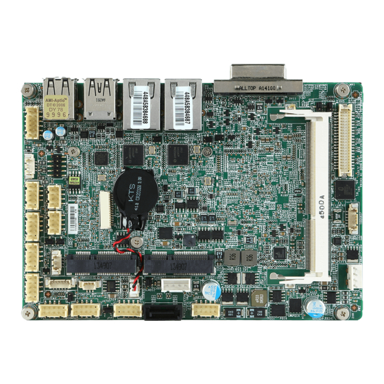
Page 12: Mainboard Layout
Overview Mainboard Layout SO-DIMM Slot DC-In 12V/19V/24V LVDS Inverter Power Connector Connector LVDS Connector LVDS Inverter Power Jumper LVDS Power Jumper Rear Panel Mini-PCIe/ mSATA Slot Intel TXE F/W Jumper GPIO Connector LAN1 Jumper SATA Power Connector SATA 2.0 Connector LAN2 Jumper Clear CMOS Jumper... -
Page 13: Me Overview
MS-98G6 ME Overview h Board Dimension unit of measurement: mm... - Page 14 Overview h Suggested Chassis I/O Gap Dimension...
-
Page 15: Chapter 2. Hardware Setup
Hardware Setup This chapter provides you with the information about hardware setup procedures. While doing the installation, be careful in holding the com- ponents and follow the installation procedures. For some components, if you install in the wrong orientation, the components will not work prop- erly. - Page 16 Hardware Setup Components Reference Guide Memory ....................2-3 Power Supply ..................2-4 DC Power Connector: JPWR2 ..............2-4 SATA Power Connector: JPW1 ..............2-4 Rear Panel I/O ...................2-5 Connector ..................2-6 Fan Power Connector: SYSFAN1 ..............2-6 GPIO Connector: JGPIO1 ................2-6 Serial ATA Connector: SATA1 ..............2-6 Front Panel Connector: JFP1 ..............2-7 LPC Debug Port Connector: JDP1 .............2-7 LVDS Inverter Connector: JINVDD1 ............2-7...
-
Page 17: Memory
MS-98G6 Memory The SO-DIMM slot is intended for memory modules. 1. Locate the SO-DIMM slot. Align the notch on the DIMM with the key on the slot and insert the DIMM into the slot. 2. Push the DIMM gently down- wards until the slot levers click and lock the DIMM in place. -
Page 18: Power Supply
Hardware Setup Power Supply DC Power Connector: JPWR2 This connector allows you to connect a 12V/ 19V/ 24V DC power adapter. SATA Power Connector: JPW1 This connector is used to provide power to SATA devices. Important Make sure that all power connectors are connected to the power supply to ensure stable operation of the motherboard. -
Page 19: Rear Panel I/O
MS-98G6 Rear Panel I/O USB 2.0 USB 2.0 LAN1 LAN2 Port Port Port Port DVI-I Port USB 3.0 USB 2.0 Port Port USB 2.0 Port The USB (Universal Serial Bus) port is for attaching USB devices such as key- board, mouse, or other USB-compatible devices. -
Page 20: Connector
Hardware Setup Connector Fan Power Connector: SYSFAN1 The fan power connector supports system cooling fans with +12V. When con- necting the wire to the connectors, always note that the red wire is the positive and should be connected to the +12V; the black wire is Ground and should be connected to GND. -
Page 21: Front Panel Connector: Jfp1
MS-98G6 Front Panel Connector: JFP1 This front panel connector is provided for electrical connection to the front panel switches & LEDs and is compliant with Intel Front Panel I/O Connectivity Design Guide. LPC Debug Port Connector: JDP1 This connectoris LPC debug port. -
Page 22: Lvds Connector: Jlvds1
Hardware Setup LVDS Connector: JLVDS1 The LVDS (Low Voltage Differential Signal) connector provides a digital interface typically used with flat panels. After connecting an LVDS interface flat panel to the JLVDS1, be sure to check the panel datasheet and set the LVDS jumper to proper power voltage. -
Page 23: Serial Port Connector: Com1 ~ Com6
MS-98G6 Serial Port Connector: COM1 ~ COM6 This connector is a 16550A high speed communications port that sends/receives 16 bytes FIFOs. You can attach a serial device to it. COM1 supports RS-232/ 422/ 485. RS-232 SIGNAL DESCRIPTION Data Carrier Detect... -
Page 24: Amplifier Connector: Jamp1
Hardware Setup Amplifier Connector: JAMP1 The JAMP1 is used to connect audio amplifiers to enhance audio performance. Audio Connector: JAUDIO1 This connector allows you to connect the front panel audio and is compliant with Intel Front Panel I/O Connectivity Design Guide. 2-10... -
Page 25: Ps/2 Keyboard/Mouse Connector: Jkbms1
MS-98G6 PS/2 Keyboard/Mouse Connector: JKBMS1 This connector is provided to connect a keyboard and a mouse. I2C/ SMBus Connector: JSMB1 This connector, known as I2C, is for users to connect System Management Bus (SMBus) interface. 2-11... -
Page 26: Jumper
Hardware Setup Jumper Important Avoid adjusting jumpers when the system is on; it will damage the motherboard. Clear CMOS Jumper: JCMOS1 There is a CMOS RAM onboard that has a power supply from an external battery to keep the data of system configuration. With the CMOS RAM, the system can automatically boot OS every time it is turned on. -
Page 27: Serial Port Power Jumper: Jcomp1~3
MS-98G6 Serial Port Power Jumper: JCOMP1 ~ JCOMP3 This jumper specifies the operation voltage of the serial ports. JCOMP1/ 2 (for COM1 ~ 4) JCOMP1 for COM1~2 JCOMP2 for COM3~4 JCOMP3 for COM5~6 +12V JCOMP3 (for COM5 ~ 6) +12V... -
Page 28: Lvds Power Jumper: Jvdd1
Hardware Setup LVDS Power Jumper: JVDD1 Use this jumper to specify the operation voltage of the LVDS interface flat panel. LVDS Inverter Power Jumper: JINV1 Use this jumper to specify the operation voltage of the interver interface flat panel. +12V Intel TXE F/W Jumper: JME1 This jumper is used to enable/disable the Intel TXE F/W. -
Page 29: Slot
MS-98G6 Slot Mini-PCIe (Peripheral Component Interconnect Express) Slot The Mini-PCIe slot is provided for 3G module, wireless LAN card, TV tuner card, Robson NAND Flash card and mSATA devices. Important • MINI_PCIE2 does not support mSATA function. • When adding or removing expansion cards, make sure that you unplug the power supply first. -
Page 31: Chapter 3. Bios Setup
BIOS Setup This chapter provides information on the BIOS Setup program and allows users to configure the system for optimal use. Users may need to run the Setup program when: ■ An error message appears on the screen at system startup and re- quests users to run SETUP. -
Page 32: Entering Setup
BIOS Setup Entering Setup Power on the computer and the system will start POST (Power On Self Test) process. When the message below appears on the screen, press <DEL> or <F2> key to enter Setup. Press <DEL> or <F2> to enter SETUP If the message disappears before you respond and you still wish to enter Setup, restart the system by turning it OFF and On or pressing the RESET button. - Page 33 MS-98G6 Control Keys ← → Select Screen ↑ ↓ Select Item Enter Select Change Option General Help Previous Values Optimized Defaults Save & Exit Exit Getting Help After entering the Setup menu, the first menu you will see is the Main Menu.
-
Page 34: The Menu Bar
BIOS Setup The Menu Bar ▶ Main Use this menu for basic system configurations, such as time, date, etc. ▶ Advanced Use this menu to set up the items of special enhanced features. ▶ Boot Use this menu to specify the priority of boot devices. ▶... -
Page 35: Main
MS-98G6 Main ▶ System Date This setting allows you to set the system date. The date format is <Day>, <Month> <Date> <Year>. ▶ System Time This setting allows you to set the system time. The time format is <Hour> <Min- ute>... -
Page 36: Advanced
BIOS Setup Advanced ▶ Bootup NumLock State This setting is to set the Num Lock status when the system is powered on. Setting to [On] will turn on the Num Lock key when the system is powered on. Setting to [Off] will allow users to use the arrow keys on the numeric keypad. - Page 37 MS-98G6 ▶ Super IO Configuration ▶ Serial Port 1/ 2/ 3/ 4/ 5/ 6 This setting enables/disables the specified serial port. ▶ Change Settings This setting is used to change the address & IRQ settings of the specified serial port.
- Page 38 BIOS Setup ▶ H/W Monitor These items display the current status of all monitored hardware devices/ components such as voltages, temperatures and the system fans speed. ▶ Smart Fan Configuration ▶ Smart SYSFAN1 Target These settings enable/disable the Smart Fan function. Smart Fan is an excel- lent feature which will adjust the system fan speed automatically depending on the current system temperature, avoiding the overheating to damage your system.
- Page 39 MS-98G6 ▶ CPU Configuration ▶ Active Processor Cores This setting specifies the number of active processor cores. ▶ Execute Disable Bit Intel’s Execute Disable Bit functionality can prevent certain classes of mali- cious “buffer overflow” attacks when combined with a supporting operating system.
- Page 40 BIOS Setup ▶ PCI/PCIE Device Configuration ▶ PCI Latency Timer This item controls how long each PCI device can hold the bus before another takes over. When set to higher values, every PCI device can conduct trans- actions for a longer time and thus improve the effective PCI bandwidth. For better PCI performance, you should set the item to higher values.
-
Page 41: Boot
MS-98G6 Boot ▶ CSM Support This setting allows users to set the device to enable/ disable the legacy BIOS ROM boot. Important If the Operating System is going to boot in UEFI mode, disable CSM Support to speed up the boot process. -
Page 42: Security
BIOS Setup Security ▶ Administrator Password Administrator Password controls access to the BIOS Setup utility. ▶ User Password User Password controls access to the system at boot and to the BIOS Setup utility. ▶ Serial Port Console Redirection ▶ Console Redirection Console Redirection operates in host systems that do not have a monitor and keyboard attached. - Page 43 MS-98G6 ▶ Console Redirection Settings ▶ Terminal Type To operate the system’s console redirection, you need a terminal support- ing ANSI terminal protocol and a RS-232 null modem cable connected be- tween the host system and terminal(s). This setting specifies the type of terminal device for console redirection.
- Page 44 BIOS Setup ▶ Security Configuration Intel TXE Configuration ▶ TXE FW Version This item displays the TXE firmware version. Read-only. ▶ TXE This setting enables/disables the TXE function. ▶ TXE HMRFPO This setting enables/disables the TXE HMRFPO (Host ME Region Flash Pro- tection Override) function.
-
Page 45: Chipset
MS-98G6 Chipset ▶ DVMT Pre-Allocated This setting defines the DVMT pre-allocated memory. Pre-allocated memory is the small amount of system memory made available at boot time by the system BIOS for video. Pre-allocated memory is also known as locked memory. This is because it is "locked"... -
Page 46: Power
BIOS Setup Power ▶ Restore AC Power Loss This setting specifies whether your system will reboot after a power failure or interrupt occurs. Available settings are: [Power Off] Leaves the computer in the power off state. [Power On] Leaves the computer in the power on state. [Last State] Restores the system to the previous status before power failure or interrupt occurred. - Page 47 MS-98G6 ** Advanced Resume Events Control ** ▶ PCIE PME This field specifies whether the system will be awakened from power saving modes when activity or input signal of onboard PCIE/PCI PME is detected. ▶ USB from S3/S4 The item allows the activity of the USB device to wake up the system from S3/S4 sleep state.
-
Page 48: Save & Exit
BIOS Setup Save & Exit ▶ Save Changes and Reset Save changes to CMOS and reset the system. ▶ Discard Changes and Exit Abandon all changes and exit the Setup Utility. ▶ Discard Changes Abandon all changes. ▶ Restore Defaults Use this menu to load the default values set by the motherboard manufacturer specifically for optimal performance of the motherboard. -
Page 49: Chapter A. Appendix Wdt & Gpio
Appendix WDT & GPIO This appendix provides the sample codes of WDT (Watch Dog Timer) and GPIO (General Purpose Input/ Output). 2-A-1... -
Page 50: Wdt Sample Code
WDT & GPIO WDT Sample Code SIO_INDEX_Port equ 04Eh SIO_DATA_Port equ 04Fh SIO_UnLock_Value equ 087h SIO_Lock_Value equ 0AAh WatchDog_LDN equ 007h WDT_UNIT equ 60h ;60h=second, 68h=minute, 40h=Disabled Watchdog timer WDT_Timer equ 30 ;ex. 30 seconds Sample code: ;Enable config mode dx, SIO_INDEX_Port al, SIO_UnLock_Value dx, al... -
Page 51: Gpio Sample Code
MS-98G6 GPIO Sample Code GPI 0 ~ GPI 3 GPI 0 GPI 1 GPI 2 GPI 3 IO Address SIO GPIO Register Sample code GPO 0 ~ GPO 3 GPO 0 GPO 1 GPO 2 GPO 3 IO Address... - Page 52 dx, SIO_DATA_Port al, dx WDT & GPIO ;al bit0 = GPI 0 status Exit SIO dx, SIO_INDEX_Port al, SIO_Lock_Value dx, al #2 : Set GPO 0 status to high ; Enable config mode dx, SIO_INDEX_Port al, SIO_UnLock_Value dx, al short $+2 ;Io_delay short $+2 ;Io_delay...
Need help?
Do you have a question about the MS-98G6 and is the answer not in the manual?
Questions and answers