Table of Contents
Advertisement
Advertisement
Table of Contents

Subscribe to Our Youtube Channel
Related Manuals for MSI 3200 Master Series


Summary of Contents for MSI 3200 Master Series
- Page 1 3200 Master Series MS-9656 (V1.X) Server Board G52-96561X1...
-
Page 2: Copyright Notice
Visit the MSI website for FAQ, technical guide, BIOS updates, driver updates, an d ot h er i n f orm at i on: h t t p: / / g l o ba l . m s i. c o m . t w / i n d e x .p h p ? func=faqIndex Contact our technical staff at: http://support.msi.com.tw/... -
Page 3: Safety Instructions
Safety Instructions Always read the safety instructions carefully. Keep this User’s Manual for future reference. Keep this equipment away from humidity. Lay this equipment on a reliable flat surface before setting it up. The openings on the enclosure are for air convection hence protects the equip- ment from overheating. -
Page 4: Fcc-B Radio Frequency Interference Statement
FCC-B Radio Frequency Interference Statement T h is eq uip men t h as been tested and found to c omply with the limits for a Class B digital device, pursuant to Part 15 of the FCC Rules. These limits are designed to provide reasonable protection against harmful interference in a residential installation. -
Page 5: Weee (Waste Electrical And Electronic Equipment) Statement
WEEE (Waste Electrical and Electronic Equipment) Statement... -
Page 8: Table Of Contents
Copyright Notice ... ii Trademarks ... ii Revision History ... ii Technical Support ... ii Safety Instructions ... iii FCC-B Radio Frequency Interference Statement ... iv W EEE (Waste Electrical and Electronic Equipment) Statement ... v Chapter 1 Getting Started ... 1-1 Mainboard Specifications ... -
Page 9: Chapter 1 Getting Started
Getting Started Chapter 1 Getting Started Thank you for choosing the 3200 Master Series (MS- 9656 V1.X), an excellent server board from MSI. ® Based on the innovative Intel 3200 & ICH9R chipsets for optimal system efficiency, the 3200 Master accom- ®... -
Page 10: Mainboard Specifications
MS-9656 Server Board Mainboard Specifications Proce ssor - Dual-Core Intel Xeon processor 3000 series, Quad-Core Intel Xeon processor 3200 series, Wolfdale and Yorkfield processors in LGA775 package - 1333/ 1066/ 800 MHz Chipset - North Bridge: Intel 3200 chipset (Intel 3200/3210 supports PCI Express graphics) - South Bridge: Intel ICH9R chipset M e mo r y... - Page 11 Getting Started Graphics - XGI Z7 graphics controller - Onboard 16MB Video SDRAM IPMI (Optional) - Hitachi H8S/2168 IPMI microcontroller Connectors Back Panel - 1 PS/2 m ouse port - 1 PS/2 keyboard port - 2 USB 2.0 ports - 1 serial port - 1 VGA port - 2 Gigabit LAN jacks Onboard Connectors...
-
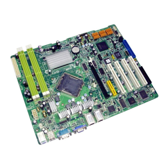
Page 12: Mainboard Layout
FRONT_FA N1 FPC1 JSPI1 Intel ICH9R JUSB3 JUSB2 J_V GA_E N1 BATT J_CMOS1 SYS_FAN2 Intel 3200 JPWR2 3200 Master Series (MS-9656 V1.X) Server Board JUSB4 FDD1 J_IDE1 JTPM1 IT8213F J_BOOT3 J_IPMB1 J_ICMB1 Chi p J_SMBUS1 J_B OOT2 PCIE1 J_BOOT1 PCIE2... -
Page 13: Chapter 2 Hardware Setup
Hardware Setup Chapter 2 Hardware Setup This chapter provides you with the information about hardware setup procedures. While doing the installation, be careful in holding the components and follow the installation procedures. For some components, if you install in the wrong orientation, the components will not work properly. -
Page 14: Quick Components Guide
MS-9656 Server Board Quick Components Guide JSPI1, p.2-12 JAPP2, p.2-14 FRONT_FAN1, p.2-13 COM2, p.2-15 FPC1, p.2-13 SATA1~6, p.2-12 J_BOOT3, p.2-18 JUSB2/3, p.2-15 J_SMBUS1, JAPP3, p.2-14 p.2-17 J_VGA_EN1, p.2-18 SYS_FAN2, p.2-13 J_CMOS1, p.2-18 CPU, p.2-3 JPWR2, DIMM Slots, p.2-9 p.2-7 JTPM1, p.2-17 JUSB4, p.2-15... -
Page 15: Cpu (Central Processing Unit)
CPU (Central Processing Unit) This mainboard supports dual-core Intel ® ® Intel Xeon processor 3200 series, W olfdale and Yorkfield processors in LGA775 package. W hen you install the CPU, make sure that you install the cooler to prevent overheating. If you do not have the CPU cooler, consult your dealer before turning on the computer. -
Page 16: Cpu & Cooler Installation
MS-9656 Server Board CPU & Cooler Installation W hen you are installing the CPU, make sure the CPU has a cooler attached on the top to prevent overheating. Meanwhile, do not forget to apply some thermal paste on CPU before installing the heat sink/cooler fan for better heat dispersion. Follow the steps below to install the CPU &... - Page 17 5. Lift the load lever up and open the load plate. 7. Visually ins pect if the CPU is seated well into the socket. If not, take out the CPU with pure vertical motion and reinstall. Important Mainboard photos shown in this section are for demonstration of the CPU/ cooler installation only.
- Page 18 MS-9656 Server Board 9. Press down the load lever lightly onto the load plate, and then se- cure the lever with the hook under retention tab. 11. Press the four hooks down to fas- ten the cooler. Then rotate the lock- ing switch (refer to the correct di- rection marked on it) to lock the hooks.
-
Page 19: Memory
Memory These DIMM slots are intended for system memory modules. DDR2 240-pin, 1.8V Dual-Channel Mode Population Rule In Dual-Channel mode, the memory modules can transmit and receive data with two data bus lines simultaneously. Dual-Channel mode is enabled when the installed memory capacities of both DIMM channels are equal. -
Page 20: Installing Memory Modules
MS-9656 Server Board Installing Memory Modules 1. The memory module has only one notch on the center and will only fit in the right orientation. 2. Insert the memory module vertically into the DIMM slot. Then push it in until the golden finger on the memory module is deeply inserted in the DIMM slot. -
Page 21: Power Supply
Power Supply 24-Pin System Power Connector: JPWR2 This connector allows you to connect a 24-pin power supply. To connect the 24-pin power supply, make sure the power supply connector is inserted in the proper orientation and the pins are aligned. Then push down the power supply firmly into the connector. You may use the 20-pin power supply as well. -
Page 22: Back Panel I/O
MS-9656 Server Board Back Panel I/O Mouse Keyboard USB Ports Serial Port M ouse/Keyboard ® The standard PS/2 mouse/keyboard DIN connector is for a PS/2 USB Port The USB (Universal Serial Bus) port is for attaching USB devices such as keyboard, mouse, or other USB-compatible devices. -
Page 23: Connector
Connector Floppy Disk Drive Connector: FDD1 This connector supports 360KB, 720KB, 1.2MB, 1.44MB or 2.88MB floppy disk drive. FDD1 IDE Connector: J_IDE1 This connector supports IDE hard disk drives, optical disk drives and other IDE devices. J_IDE1 Important If you install two IDE devices on the same cable, you must configure the drives separately to master / slave mode by setting jumpers. - Page 24 MS-9656 Server Board SPI Flash ROM Connector: JSPI1 This connector is used to flash SPI flash ROM. JSPI1 Serial ATA Connector: SATA1 ~ SATA6 This connector is a high-speed Serial ATA interface port. Each connector can con- nect to one Serial ATA device. SATA1 SATA2 SATA3 SATA4...
-
Page 25: Fan Power Connector
DVD/CD-ROM Connector: FPC1 (Optional) This connector is designed to connect slim DVD/CD-ROM drive. Chassis Intrusion Switch Connector: JINT1 This connector connects to the chassis intrusion switch cable. If the chassis is opened, the chassis intrusion mechanism will be activated. The system will record this status and show a warning message on the screen. - Page 26 MS-9656 Server Board Front Panel Connector: JAPP1, JAPP2, JAPP3 (Optional) These are proprietary front panel connectors that provide I signal connection, and electrical connection to the front panel switches/LEDs. JAPP1 JAPP2 JAPP3 2-14 C bus connection, serial JAPP1 Pin Definition SIGNAL SIGNAL +5VSB...
-
Page 27: Serial Port Connector: Com2
Serial Port Connector: COM2 This connector is a 16550A high speed communications port that sends/receives 16 bytes FIFOs. You can attach a serial device to it. COM2 Front USB Connector: JUSB2, JUSB3, JUSB4 This connector, compliant with Intel necting high-speed USB interface peripherals such as USB HDD, digital cameras, M P3 players, printers, modems and the like. - Page 28 MS-9656 Server Board BMC Connector: J_BOOT1, J_BOOT2, J_IPMB1, J_ICMB1, J1 These connec tors are used to control the H8 BMC (Baseboard Management Controller). J_BOOT1 Pin Definition SIGNAL BOOT_TXD_CON BOOT_RXD_CON J_IPMB1 Pin Definition SIGNAL IPMB_DATA IPMB_CLK 2-16 J_BOOT2 Pin Definition SIGNAL Boot Mode J_ICMB1 Pin Definition...
- Page 29 I2C Bus Connector: J_SMBUS1 The mainboard provides one I2C (also known as I connect System Management Bus (SMBus) interface. J_SMBUS1 TPM Connector: JTPM1 (Optional) This connector connects to an optional TPM (Trusted Platform Module). Please refer to the TPM security platform manual for more details. JTPM 1 SIGNAL DESCRIPTION...
-
Page 30: Jumper
MS-9656 Server Board Jumper VGA Jumper: J_VGA_EN1 This jumper is used to enable or disable the onboard VGA controller. J_VGA_EN1 BIOS Recovery Jumper: J_BOOT3 Users can short connect pin#2-3 to recover the system BIOS with a Recovery Floppy. W hen the system is done with the job, the buzzer will beep to remind the user to set the jumper to its normal state (pin#1-2 short connected). -
Page 31: Slot
Slot PCI (Peripheral Component Interconnect) Express Slot The PCI Express slot supports the PCI Express interface expansion card. The standard PCI Express x16 slot supports up to 4.0 GB/s transfer rate. But the onboard PCI Express x16 slot only supports x8 signal with up to 2.0 GB/s transfer rate. -
Page 32: Pci Interrupt Request Routing
MS-9656 Server Board PCI Interrupt Request Routing The IRQ, acronym of interrupt request line and pronounced I-R-Q, are hardware lines over which devices can send interrupt signals to the microprocessor. The PCI IRQ pins are typically connected to the PCI bus pins as follows: DEVICE Interrupt XGI Z7... -
Page 33: Chapter 3 Bios Setup
Chapter 3 BIOS Setup This chapter provides information on the BIOS Setup program and allows you to configure the system for optimum use. You may need to run the Setup program when: ² An error message appears on the screen during the system booting up, and requests you to run SETUP. -
Page 34: Entering Setup
MS-9656 Server Board Entering Setup Power on the computer and the system will start POST (Power On Self Test) process. W hen the message below appears on the screen, press <Del> key to enter Setup. Press Del to enter SETUP If the message disappears before you respond and you still wish to enter Setup, restart the system by turning it OFF and On or pressing the RESET button. -
Page 35: Control Keys
Control Keys < > Move to the previous item < > Move to the next item < > Move to the item in the left hand < > Move to the item in the right hand <Enter> Select the item <Esc>... -
Page 36: The Menu Bar
MS-9656 Server Board The Menu Bar Main Use this menu for basic system configurations, such as time, date etc. Advanced Use this menu to set up the items of special enhanced features. Boot Use this menu to specify the priority of boot devices. Security Use this menu to set supervisor and user passwords. -
Page 37: Main
Main AM I BIOS, Processor, System M emory These items show the firmware and hardware specifications of your system. Read only. System Time This setting allows you to set the system time. The time format is <Hour> <Minute> <Second>. System Date This setting allows you to set the system date. -
Page 38: Advanced
MS-9656 Server Board Advanced For mainboards with IPMI chip For mainboards without IPM I chip... - Page 39 CPU Configuration Execute Disable Bit Capability Intel's Execute Disable Bit functionality can prevent certain classes of malicious "buffer overflow" attacks when combined with a supporting operating system. This functionality allows the processor to classify areas in memory by where application code can execute and where it cannot. W hen a malicious worm attempts to insert code in the buffer, the processor disables code execution, preventing damage or worm propagation.
- Page 40 MS-9656 Server Board IDE Configuration SATA#1 Configuration, SATA#2 Configuration These settings specify the operation modes of the SATA ports. Configure SATA#1 as s This setting specifies the function of the on-chip SATA controller. Primary/Secondary/Third/Fourth/Fifth/Sixth IDE Master/Slave...
- Page 41 [Type] [LBA/Large Mode] [Block(Multi-Sector Transfer)] Any selection except Disabled determines [PIO Mode] [DMA Mode] [S.M.A.R.T.] [32 Bit Data Transfer] Floppy Configuration Floppy A, Floppy B This setting allows you to set the type of floppy drives installed. Press PgUp/<+> or PgDn/<-> to select [Manual], [None] or [Auto] type.
- Page 42 MS-9656 Server Board Onboard LANs Configuration GbE LAN1 (82573) Controller, GbE LAN2 (82566) Controller These settings disable/enable the specified LAN controllers. GbE LAN1 (82573) Boot ROM, GbE LAN2 (82566) Boot ROM The items enable or disable the initialization of the onboard LAN Boot ROMs during bootup.
- Page 43 Super IO Configuration Onboard Floppy Controller This setting disables/enables the onboard floppy disk drive controller. Serial Port 1 Address, Serial Port 2 Address Select an address and a corresponding interrupt for the serial port 1/2. BIOS Setup 3-11...
- Page 44 MS-9656 Server Board Hardware Health Configuration These items display the current status of all of the monitored hardware devices/ components such as voltages, temperatures and all fans’ speeds. CPU FAN Mode Setting This setting controls the Smart Fan feature. Smart Fan is an excellent feature which will adjust the CPU/system fan speed automatically depending on the current CPU/system temperature.
- Page 45 APM Configuration Resume On Ring An input signal on the serial Ring Indicator (RI) line (in other words, an incoming call on the modem) awakens the system from a soft off state. Resume On PME# of PCI Slots W hen setting to [Enabled], this setting allows your system to be awakened from the power saving modes through any PME (Power Management Event) on PCI slots.
- Page 46 MS-9656 Server Board Event Log Configuration View Event Log Press [Enter] to view the contents of the DMI event log. Mark All Events as Read d Press [Enter] and a screen pops up, asking users to confirm whether or not to clear all DMI event logs immediately.
- Page 47 IPMI 2.0 Configuration (for mainboards with IPM I chip) Status of BM C, BM C Firmware Version These settings show the status of the BMC (Baseboard Management Controller) chip and its firmware version. Read only. View BM C System Event Log Use this function to view system event logs recorded by BMC.
- Page 48 MS-9656 Server Board BMC Watch Dog Timer Action The system watch-dog timer is a hardware timer that generates either an NMI or a reset when the software that it monitors does not respond as expected each time the watch dog polls it. Notify BMC FAN Type This setting specifies the BMC fan type.
- Page 49 Terminal Type To operate the system’s console redirection, you need a terminal supporting ANSI terminal protocol and a RS-232 null modem cable connected between the host system and terminal(s). This setting specifies the type of terminal device for console redirection. VT-UTF8 Combo Key Support This setting enables/disables the VT-UTF8 combination key support for ANSI/ VT100 terminals.
- Page 50 MS-9656 Server Board TPM Enable/Disable Status This setting displays the TPM enable/disable status. Read only. TPM Owner Status This setting shows the TPM ownership. Read only. USB Configuration Legacy USB Support Set to [Enabled] if you need to use any USB 1.1/2.0 device in the operating system that does not support or have any USB 1.1/2.0 driver installed, such as DOS and SCO Unix.
- Page 51 USB Mass Storage Device Configuration USB Mass Storage Reset Delay This setting controls the number of seconds the POST waits for the USB mass storage device after the start unit command is sent. Emulation Type This setting enables you to set the type of device you want the USB mass storage device to emulate.
-
Page 52: Boot
MS-9656 Server Board Boot Boot Settings Configuration 3-20... - Page 53 Quiet Boot This BIOS feature determines if the BIOS should hide the normal POST mes- sages with the motherboard or system manufacturer's full-screen logo. W hen it is enabled, the BIOS will display the full-screen logo during the boot-up sequence, hiding normal POST messages.
- Page 54 MS-9656 Server Board W hen disabled, the ROM BIOS of these host adaptors will not be able to "cap- ture" Interrupt 19. Therefore, you will not be able to boot operating systems from any bootable disks attached to these host adaptors. Nor will you be able to gain access to their ROM setup utilities.
-
Page 55: Security
Security Supervisor Password / Change Supervisor Password Supervisor Password controls access to the BIOS Setup utility. These settings allow you to set or change the supervisor password. User Password / Change User Password / Clear User Password User Password controls access to the system at boot. These settings allow you to set, change, or clear the user password. -
Page 56: Chipset
MS-9656 Server Board Chipset North Bridge Configuration 3-24... - Page 57 ECC Function This setting enables/disables ECC (Error Correction Code) checking, a method of checking the integrity of data in DRAM. ECC provides more elaborate error detection than parity; ECC can detect multiple-bit errors and can locate and correct single-bit errors. M emory Remap Feature The memory remapping feature allows for the segment of system memory that was previously overwritten by the Peripheral Component Interconnect (PCI)
-
Page 58: Exit
MS-9656 Server Board Exit Save Changes and Exit Save changes to CMOS and exit the Setup Utility. Discard Changes and Exit Abandon all changes and exit the Setup Utility. Discard Changes Abandon all changes and continue with the Setup Utility. Load Optimal Defaults Use this menu to load the default values set by the mainboard manufacturer specifi- cally for optimal performance of the mainboard. -
Page 59: Appendix A Intel Ich9R Sata Raid
Appendix A Intel ICH9R SATA RAID This appendix will assist users in configuring and en- abling RAID functionality on platforms The ICH9R RAID s olution s upports RAID level 0 (striping), RAID level 1 (mirroring), RAID level 5 (striping with parity) and RAID level 10 (striping and mirroring). Intel ICH9R SATA RAID... -
Page 60: Ich9R Introduction
MS-9656 Server Board ICH9R Introduction The ICH9R provides a hybrid solution that combines 6 independent SATAII ports for support of up to 6 Serial ATAII (Serial ATAII RAID) drives. Serial ATAII (SATAII) is the latest generation of the ATA interface. SATA hard drives deliver blistering transfer speeds up to 300MB/sec. -
Page 61: Bios Configuration
BIOS Configuration The Intel Matrix Storage Manager Option ROM should be integrated with the system BIOS on all motherboards with a supported Intel chipset. The Intel Matrix Stroage Manager Option ROM is the Intel RAID implementation and provides BIOS and DOS disk services. - Page 62 MS-9656 Server Board After pressing the <Ctrl> and <I> keys simultaneously, the following window will appear: (1) Create RAID Volume Select option 1 “Create RAID Volume” and press <Enter> key. The following screen appears. Then in the Name field, specify a RAID Volume name and then press the <TAB>...
- Page 63 In the Disk field, press <Enter> key and the following screen appears. Use <Space> key to select the disks you want to create for the RAID volume, then click <Enter> key to finish selection. Then select the strip value for the RAID array by using the “upper arrow” or “down arrow”...
- Page 64 MS-9656 Server Board Important Since you want to create two volumes (Intel Matrix RAID Technology), this default size (maximum) needs to be reduced. Type in a new size for the first volume. As an example: if you want the first volume to span the first half of the two disks, re-type the size to be half of what is shown by default.
- Page 65 (2) Delete RAID Volume Here you can delete the RAID volume, but please be noted that all data on RAID drives will be lost. Important If your system currently boots to RAID and you delete the RAID volume in the Intel RAID Option ROM, your system will become unbootable.
- Page 66 MS-9656 Server Board (3) Reset Disks to Non-RAID Select option 3 Reset Disks to Non-RAID and press <Enter> to delete the RAID volume and remove any RAID structures from the drives. The following screen appears: Press <Y> key to accept the selection. Important 1.
-
Page 67: Installing Driver
Important Please follow the instruction below to make an “Intel yourself. 1. Insert the MSI CD into the CD-ROM drive. 2. Click the “Browse CD” on the Setup screen. 3. Copy all the contents in \\IDE\Intel\ICH9R\Floppy to a formatted floppy diskette. - Page 68 MS-9656 Server Board † Confirming Windows Vista/XP/2000 Driver Installation 1. From W indows Vista/XP/2000, open the Control Panel from My Computer followed by the System icon. 2. Choose the Hardware tab, then click the Device M anager tab. 3. Click the "+" in front of the SCSI and RAID Controllers hardware type. The driver Intel(R) ICH9R SATA RAID Controller should appear.
-
Page 69: Installing Software
For this reason, you cannot remove or un-install this driver from the system after installation; however, you will have the ability to un-install all other non-driver components. Insert the MSI CD and click on the Intel M atrix Storage M anager to install the s of tware. Click on this item... - Page 70 MS-9656 Server Board The InstallShield Wizard will begin automatically for installation showed as following: Click on the Next button to proceed the installation in the welcoming window. A-12...
- Page 71 Intel ICH9R SATA RAID The window shows the components to be installed. Click Next button to continue. After reading the license agreement in the following window, click Yes button to continue. A-13...
- Page 72 MS-9656 Server Board The following window appears to show the Readme File Information. It shows the system requirements and installation information. Once the installation is complete, the following window appears. A-14...
-
Page 73: Raid Migration Instructions
RAID Migration Instructions The Intel Matrix Storage Console offers the flexibility to upgrade from a single Serial ATA (SATA) hard drive to RAID configuration when an additional SATA hard drive is added to the system. This process will create a new RAID volume from an existing disk. -
Page 74: Create Raid Volume From Existing Disk
MS-9656 Server Board Create RAID Volume from Existing Disk To create a RAID volume from an existing disk, choose Action --> Create RAID Volume from Existing Hard Drive. Note: The “Action” button only appears in advance mode. To enable the advance mode, go to View -->... - Page 75 (1) Step 1: Configure Volume Here you can configure the new RAID volume by entering the volume name, selecting the RAID level and strip size. † RAID Volume Name: A desired RAID volume name needs to be typed in where the ‘RAID_Volume1’ text currently appears above.
- Page 76 MS-9656 Server Board RAID 10 (Mirrored Stripes) – A RAID 1 array of two RAID 0 arrays. † Strip Sizes: Select the desired strip size setting. As indicated, the optimal setting is 128KB. Se- lecting any other option may result in performance degradation. Even though 128KB is the recommended setting for most users, you should choose the strip size value which is best suited to your specific RAID usage model.
- Page 77 Intel ICH9R SATA RAID (3) Select Member Hard Drive(s) Then select the member disk (the target disk) that you wish to use and then click “- -->” to move it to the Selected field. Then click Next to continue. Please note that the existing data on the selected hard drive(s) will be deleted permanently.
- Page 78 MS-9656 Server Board (4) Specify Volume Size Specify the amount of available array space to be used by the new RAID volume. You may enter the amount in the space or use the slider to specify. It is recommended you use 100% of the available space for the optimized usage.
- Page 79 Intel ICH9R SATA RAID (6) Start Migration The migration process may take up to two hours to complete depending on the size of the disks being used and the strip size selected. A dialogue window will appear stating that the migration process may take considerable time to complete, meanwhile a popup dialogue at the taskbar will also show the migration status.
-
Page 80: Degraded Raid Array
MS-9656 Server Board Degraded RAID Array A RAID 1, RAID 5 or RAID 10 volume is reported as degraded when one of its hard drive members fails or is temporarily disconnected, and data mirroring is lost. As a result, the system can only utilize theremaining functional hard drive member. To re- establish data mirroring and restore data redundancy, refer to the procedure below that corresponds to the current situation. - Page 81 5. Exit Intel RAID Option ROM, and then reboot to W indows system. 6. W hen prompted to rebuild the RAID volume, click 'Yes'. 7. The Intel(R) Storage Utility will be launched. Right-click the new hard drive and select 'Rebuild to this Disk'. The 'Rebuild W izard' will be launched which will guide you through the process of rebuilding to the new hard drive.
Need help?
Do you have a question about the 3200 Master Series and is the answer not in the manual?
Questions and answers