Table of Contents
Advertisement
Quick Links
Advertisement
Table of Contents

Related Manuals for MSI MS-9802


Summary of Contents for MSI MS-9802
- Page 1 Fuzzy CX700/CX700D MS-9802 (V1.X) Mainboard G52-98021X1...
-
Page 2: Copyright Notice
Alternatively, please try the following help resources for further guidance. Visit the MSI website at faq/esc_faq_list.php updates, and other information. Contact our technical staff at http://support.msi.com.tw/. Date February 2007 http://www.msi.com.tw/program/service/faq/ for FAQ, technical guide, BIOS updates, driver... -
Page 3: Safety Instructions
Safety Instructions Always read the safety instructions carefully. Keep this User’s Manual for future reference. Keep this equipment away from humidity. Lay this equipment on a reliable flat surface before setting it up. The openings on the enclosure are for air convection hence protects the equip- ment from overheating. -
Page 4: Fcc-B Radio Frequency Interference Statement
This device complies with Part 15 of the FCC Rules. Operation is subject to the following two conditions: (1) this device may not cause harmful interference, and (2) this device must accept any interference received, including interference that may cause undesired operation. Micro-Star International MS-9802... -
Page 5: Weee (Waste Electrical And Electronic Equipment) Statement
WEEE (Waste Electrical and Electronic Equipment) Statement... -
Page 8: Table Of Contents
Copyright Notice ... iii Trademarks ... iii Revision History ... iii Technical Support ... iii Safety Instructions ... iii FCC-B Radio Frequency Interference Statement ... v WEEE (Waste Electrical and Electronic Equipment) Statement ... v Chapter 1 Product Overview ... 1-1 Mainboard Layout ... - Page 9 Parallel Port Header: JLPT1 ... 4-12 Fan Power Connectors: CPUFAN1, SYSFAN1 ... 4-12 Serial Port Connector: COM3, COM4 ... 4-13 Front USB Connector: F_USB1 ... 4-13 CD-In Connector: JCD1 ... 4-14 LVDS Flat Panel Connector: JLVDS1 ... 4-14 IrDA Infrared Module Header: IRDA1 ... 4-15 I2C Bus Connector: J1 ...
- Page 10 Award POST Code ... 6-4 Check Point & Beep Code List ... 6-10 PCI Configuration ... 6-16 Resource List ... 6-19...
-
Page 11: Chapter 1 Product Overview
Chapter 1 Product Overview Thank you for choosing the Fuzzy CX700/CX700D (MS- 9802 v1.X) Mini ITX mainboard from MSI. Noiseless, fanless and low power consumption are the advantages of the Fuzzy CX700/CX700D, making it an ideal choice for IPC special application. -
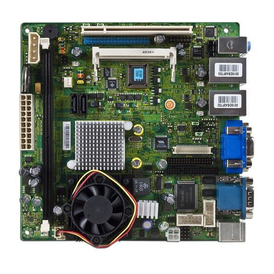
Page 12: Mainboard Layout
Top: LAN Jack Bottom: USB Ports Top: LAN Jack Bo ttom: USB Ports T: Li ne-In M: Li ne- Ou t B: Mic-In Fuzzy CX700/CX700D (MS-9802 v1.X) Mini ITX Mainboard COM3 V IA COM4 C7 CP U JLP T1 V IA... -
Page 13: Chapter 2 Product Specifications
Chapter 2 Product Specifications Based on the innovative VIA CX700/ CX700M/ CX700M2 controller for optimal system efficiency, the Fuzzy CX700/CX700D accommodates VIA C7/ Eden/ Eden ULV processor and supports one 240-pin 400/533MHz DDR2 DIMM slot to provide the maximum of 2GB memory capacity. -
Page 14: Mainboard Specifications
MS-9802 Mainboard Mainboard Specifications Processor Support - VIA C7/ Eden/ Eden ULV processor with nanoBGA2 footprint - 3-pin CPU fan pinheader with Smart Fan Speed Control - Power Saver Technology enabled Supported FSB - 400/ 533 MHz Chipset - Single chip solution: VIA CX700/ CX700M/ CX700M2... - Page 15 Environmental Operating Temperature - Temperature: -10 C ~ 70 - Humidity: 0% ~ 85% RH Storage Temperature - Temperature: -20 C ~ 80 - Humidity: 25% ~ 90% RH For more information on compatible components, please visit http://www.msi.com.tw/program/products/server/svr/pro_svr_qvl.php Product Specifications...
-
Page 16: Safety Compliance & Mtbf
MS-9802 Mainboard Safety Compliance & MTBF Standard number Certification EN 55022:1998+A1:2000+A2:2003 Class B Product family standard EN 6100-3-2:2000 Class D EN 6100-3-3:1995+A1:2001 Immunity EN 55024:1998+A1:2001+A2:2003 BSMI CNS 13438 乙類(1997年版) AS/NZS CISPR 22:2004 C-Tick FCC CFR Title 47 Part 15 Subpart B: 2005 Class B... -
Page 17: Block Diagram
Product Specifications Block Diagram... -
Page 18: Board Dimension
MS-9802 Mainboard Board Dimension... -
Page 19: I/O Shield Drawing
Product Specifications I/O Shield Drawing... - Page 20 MS-9802 Mainboard...
-
Page 21: Chapter 3 Electrical Specifications
Chapter 3 Electrical Specifications This chapter provides detailed electrical specifications of this mainboard. For safety concern, users are ad- vised to read this chapter first before powering on the mainboard. Electrical Specifications... -
Page 22: Power Consumption
MS-9802 Mainboard Power Consumption Configuration CPU:VIA C7 1GHz Memory:Samsung PC2-3200 1GB SATA HDD:HITACHI 80GB SATA HDD:Maxtor 80GB CDROM:Samsung CD-RW/DVD Mainboard +3.3V Current (A) A. Full Running (CPU / 1.33 Memory / HDD / LAN stress & Play Audio CD) B. Running Network 1.33... -
Page 23: General Purpose I/O Lines
General Purpose I/O Lines General Purpose I/O Lines Parameter Input High Voltage (VIH) Input High Voltage (VIL) Input Current (II) Out High Voltage (VoH) Out Low Voltage (VoL) Electrical Specifications Conditions -0.5V IOH = -50uA 4.4V IOH = -16uA 3.8V IOL = 50uA IOH = 16uA 0.8V... -
Page 24: Onboard Connector Part Number
MS-9802 Mainboard Onboard Connector Part Number Onboard Connector Part Number DC 12V power connector HORNG TONG ( E20221-222123 ) AMP audio header FOXCONN ( HB1104H ) GPIO box header HORNG TONG ( A10271-0A1129 ) Parallel port box header HORNG TONG ( A26371-0A1120 ) -
Page 25: Chapter 4 Hardware Setup
Chapter 4 Hardware Setup This chapter provides you with the information about hardware setup procedures. While doing the installation, be careful in holding the components and follow the installation procedures. For some components, if you install in the wrong orientation, the components will not work properly. -
Page 26: Quick Components Guide
MS-9802 Mainboard Quick Components Guide COM3, p.4-13 Back Panel, p.4-5 J LPT1 , p.4-12 JLVDS1, p.4-14 J7, p.4-17 JTV1, p.4-15 TV/CRT1, p.4-16 JAUD1, p.4-9 JCD1, p.4-14 JAUD2, p.4-9 COM4, p.4-13 J2~J5, p.4-17 CPUFAN1, p.4-12 PCI1, p.4-18 JCF_SEL1, p.4-7 MINIPCI1, CLR_CMOS1, p.4-19... -
Page 27: Memory
Memory The mainboard provides one 240-pin non-ECC DDR2 400/533 and ECC DDR2 400 DIMM slot and supports up to 2GB system memory. For more information on compatible components, please visit http://www.msi.com. tw/program/products/server/svr/pro_svr_qvl.php. DDR2 240-pin, 1.8V Installing DDR2 Modules 1. The memory module has only one notch on the center and will only fit in the right orientation. -
Page 28: Power Supply
MS-9802 Mainboard Power Supply ATX 20-Pin System Power Connector: ATX1 This connector allows you to connect to an ATX power supply. To connect to the ATX power supply, make sure the plug of the power supply is inserted in the proper orientation and the pins are aligned. -
Page 29: Back Panel
Back Panel Serial Port M ouse Keyboard Serial Port Mouse/Keyboard Connector ® The standard PS/2 mouse/keyboard DIN connector is for a PS/2 Serial Port The serial port is a 16550A high speed communications port that sends/ receives 16 bytes FIFOs. You can attach a serial mouse or other serial devices directly to the connector. - Page 30 MS-9802 Mainboard LAN (RJ-45) Jacks The standard RJ-45 jacks are for connection to Local Area Network (LAN). You can connect network cables to them. LED Color 10M Cable Plug-in No Transmission Transition 100M Cable Plug-in No Transmission Transition 1000M Cable Plug-in...
-
Page 31: Cf Mode Selecting Jumper: Jcf_Sel1
Connectors IDE Connector: IDEB1 The mainboard has a 32-bit Enhanced PCI IDE and Ultra DMA 33/66/100/133 controller that provides PIO mode 0~4, Bus Master, and Ultra DMA 33/66/100/133 function. You can connect hard disk drives, CD-ROM and other IDE devices. The Ultra ATA133 interface boosts data transfer rates between the computer and the hard drive up to 133 megabytes (MB) per second. -
Page 32: Serial Ata Connectors: Sata1, Sata2
MS-9802 Mainboard Serial ATA Connectors: SATA1, SATA2 SATA1~SATA2 are high-speed SATA interface ports and support SATA data rates of 300MB/s. Each SATA connector can connect to 1 hard disk device and is fully compliant with Serial ATA 2.0 specifications. Serial ATA cable... -
Page 33: Audio Amplifier Connector: Jaud1
Audio Amplifier Connector: JAUD1 The 6W JAUD1 is used to connect audio amplifiers to enhance audio performance. JAUD1 Front Audio Connector: JAUD2 This connector is designed to connect an optional audio bracket that provides extra front panel audio IO jacks. JAUD2 Pin Definition SIGNAL... -
Page 34: Front Panel Connector: Jfp1
MS-9802 Mainboard Front Panel Connector: JFP1 The mainboard provides one front panel connector for electrical connection to the front panel switches and LEDs. The JFP1 is compliant with Intel Connectivity Design Guide. JFP1 Power Power Reset Switch Switch Reset Circuit VCC3 4.7K ohm... -
Page 35: Digital Io Connector: J6
Power LED Circuit VCC5_SB 330 ohm PWR_LED SUS_LED VCC5_SB 330 ohm Power Button Circuit VCC3_SB 4.7K ohm PWRBTN Digital IO Connector: J6 The J6 connects to the General-Purpose Input/Output (GPIO) peripheral module. DIO Circuit 74LV244A 74LV244A External circuit 68 ohm 0.1uf 100 ohm External circuit... -
Page 36: Parallel Port Header: Jlpt1
MS-9802 Mainboard Parallel Port Header: JLPT1 The mainboard provides a 26-pin header for connection to an optional parallel port bracket. The parallel port is a standard printer port that supports Enhanced Parallel Port (EPP) and Extended Capabilities Parallel Port (ECP) mode. -
Page 37: Serial Port Connector: Com3, Com4
Serial Port Connector: COM3, COM4 The mainboard provides two 9-pin headers as serial ports. These ports are 16550A high speed communication port that sends/receives 16 bytes FIFOs. You can attach a serial mouse or other serial devices directly to them. COM3 COM4 Front USB Connector: F_USB1... -
Page 38: Cd-In Connector: Jcd1
MS-9802 Mainboard CD-In Connector: JCD1 The connector is for CD-ROM audio connector. LVDS Flat Panel Connector: JLVDS1 The LVDS (Low Voltage Differential Signal) connector provides a digital interface ty p i ca l l y u se d w it h fl at p a n e l s. Aft er... -
Page 39: Irda Infrared Module Header: Irda1
TV-Out Connector: JTV1 The mainboard provides a TV-Out connector. Display Matrix LVDS LVDS TV OUT V : Support X : No Support IrDA Infrared Module Header: IRDA1 The connector allows you to connect to IrDA Infrared module. You must configure the setting through the BIOS setup to use the IR function. -
Page 40: Clear Cmos Jumper: Clr_Cmos1
MS-9802 Mainboard Jumpers Display Jumper: TV/CRT1 This jumper is used to select the display type. TV/CRT1 LVDS TV OUT Clear CMOS Jumper: CLR_CMOS1 There is a CMOS RAM onboard that has a power supply from external battery to keep the data of system configuration. With the CMOS RAM, the system can automatically boot OS every time it is turned on. -
Page 41: Lcd Power Source Jumper: J7
LCD Power Source Jumper: J7 This jumper is used to select the power source of LCD. COM Port Power Jumpers: J2, J3, J4, J5 These jumpers specify the operation voltage of the serial port COM1~4. J2 -> COM2 J3 -> COM1 J4 ->... -
Page 42: Slots
MS-9802 Mainboard Slots PCI (Peripheral Component Interconnect) Slot The PCI slot supports LAN cards, SCSI cards, USB cards, and other add-on cards that comply with PCI specifications. At 32 bits and 33 MHz, it yields a throughput rate of 133 MBps. -
Page 43: Mini Pci Slot
Mini PCI Slot This is a 32 bits, 33 MHz and 133 MBps PCI slot, only select the MiniPCI adapters can be installed. Installing Mini PCI Cards 1. Insert the card at an angle of 45 degrees into the Mini PCI slot, Line up the notch in the card with the small tab in the slot and slide the card into the slot until the golden finger is almost invisible. -
Page 44: Removing Mini Pci Cards
MS-9802 Mainboard Removing Mini PCI Cards If you need to remove a card in the Mini PCI slot, spread the tabs in the slot away from the notches in the card. The card should pop up slightly. Lift the card to a 45-degree angle and then gently slide the card out of the slot. -
Page 45: Chapter 5 Bios Setup
Chapter 5 BIOS Setup This chapter provides information on the BIOS Setup program and allows you to configure the system for optimum use. You may need to run the Setup program when: ² An error message appears on the screen during the system booting up, and requests you to run SETUP. -
Page 46: Entering Setup
MS-9802 Mainboard Entering Setup Power on the computer and the system will start POST (Power On Self Test) process. When the message below appears on the screen, press <F1> key to enter Setup. Press F1 to enter SETUP If the message disappears before you respond and you still wish to enter Setup, restart the system by turning it OFF and On or pressing the RESET button. -
Page 47: Control Keys
Control Keys < > Move to the previous item < > Move to the next item < > Move to the item in the left hand < > Move to the item in the right hand Select the item <Enter> Jumps to the Exit menu or returns to the main menu from a <Esc>... -
Page 48: The Menu Bar
MS-9802 Mainboard The Menu Bar Main Use this menu for basic system configurations, such as time, date etc. Advanced Use this menu to set up the items of special enhanced features available on your system’s chipset. Boot Use this menu to specify the priority of boot devices. -
Page 49: Main
Main Date (mm:dd:yy) The date format is <Day>, <Month> <Date> <Year>. Time (hh:mm:ss) The time format is <Hour> <Minute> <Second>. IDE Channel 0/1 Master/Slave Press <Enter> to enter the sub-menu. IDE HDD Auto-Detection Press [Enter] to auto-detect the HDD on this channel. If detection is successful, it fills the remaining fields on this menu. - Page 50 MS-9802 Mainboard Capacity This setting shows the formatted size of the storage device. Note that this size is usually slightly greater than the size of a formatted disk given by a disk checking program. Cylinder Set the number of cylinders for this hard disk.
-
Page 51: Advanced
BIOS Setup Advanced Advanced BIOS Features Virus Warning The item is to set the Virus Warning feature for IDE Hard Disk boot sector... - Page 52 MS-9802 Mainboard protection. If the function is enabled and any attempt to write data into this area is made, BIOS will display a warning message on screen and beep. Quick Power On Self Test Select [Enabled] to reduce the amount of time required to run the power-on self- test (POST).
- Page 53 Advanced Chipset Features AGP & P2P Bridge Control VGA Share Memory Size The system shares memory to the onboard VGA card. This setting controls the exact memory size shared to the VGA card. Direct Frame Buffer When [Enabled], a fixed VGA frame buffer from A000h to BFFFh and a CPU- to-PCI write buffer are implemented.
- Page 54 MS-9802 Mainboard Select Display Device Use the field to select the type of device you want to use as the display(s) of the system. Panel Type Use this field to specify the panel type. Output Port Use this field to specify the video output channel.
- Page 55 HDTV Type Select the HDTV standard which is used as the video signal format of your HDTV if you have connected a HDTV to the system. HDTV Connector This setting specifies the HDTV connector. System BIOS Cacheable Selecting [Enabled] allows caching of the system BIOS ROM at F0000h-FFFFFh, resulting in better system performance.
- Page 56 MS-9802 Mainboard Integrated Peripherals VIA OnChip IDE Device SATA Controller This setting enables/disables the on-chip SATA controller. IDE DMA Transfer Access Setting to [Enabled] will open DMA bus master and execute DMA action in DOS, which will make the data transferring faster.
- Page 57 OnChip IDE Channel 1 The integrated peripheral controller contains an IDE interface with support for one IDE channel. Choose [Enabled] to activate the IDE channel 1. IDE Prefetch Mode The onboard IDE drive interfaces support IDE prefetching, for faster drive accesses.
- Page 58 MS-9802 Mainboard Azalia HDA Controller Azalia is the codename of “High Definition Audio.” This setting controls the High Definition Audio interface integrated in the Southbridge. Super IO Device Onboard Serial Port 1 / 2 Select an address and corresponding interrupt for Serial Port 1/2.
- Page 59 Use IR Pins Consult your IR peripheral documentation to select the correct setting of the TxD and RxD signals. Onboard Serial Port 3 / 4 Select an address and corresponding interrupt for Serial Port 3/4. Onboard Parallel Port This setting specifies the I/O port address and IRQ of the onboard parallel port.
- Page 60 MS-9802 Mainboard USB 1.1 Controller This setting is used to enable/disable the onboard USB 1.1 controller. USB 2.0 Controller This setting is used to enable/disable the onboard USB 2.0 controller. USB Operation Mode This setting controls the USB operation speed.
- Page 61 [S3(STR)] The S3 sleep mode is a lower power state where the information of system configuration and open appli- cations/files is saved to main memory that remains powered while most other hardware components turn off to save energy. The information stored in memory will be used to restore the system when a “wake up”...
- Page 62 MS-9802 Mainboard Wakeup Event Detect PS2 KB Wakeup Select The item specifies how the system will be awakened from power saving mode when input signal of the PS2 keyboard is detected. Use the <PageUp> & <PageDown> keys to select the options. When selecting [Password], enter the desired password.
- Page 63 PnP/PCI Configurations PNP OS Installed When set to [Yes], BIOS will only initialize the PnP cards used for booting (VGA, IDE, SCSI). The rest of the cards will be initialized by the PnP operating system like Windows 98. When set to [No], BIOS will initialize all the PnP cards. So, select [Yes] if your operating system is Plug &...
- Page 64 MS-9802 Mainboard must be removed from the IRQ pool, the end user can use these settings to reserve the IRQ by assigning an [Reserved] setting to it. Onboard I/O is configured by BIOS. All IRQs used by onboard I/O are configured as [Available].
-
Page 65: Boot
Boot Hard Disk Boot Priority This setting allows users to set the boot priority of the specified hard disk devices. First press <Enter> to enter the sub-menu. Then you may use the arrow keys ( to select the desired device, then press <+>, <-> or <PageUp>, <PageDown> key to move it up/down in the priority list. - Page 66 MS-9802 Mainboard Security Security Option Select whether the password is required every time the system boots or only when you enter Setup. System The system will not boot and access to Setup will be denied if the correct password is not entered at the prompt.
-
Page 67: System
BIOS Setup System System Summary These items show the hardware specifications of your system. Read only. 5-23... - Page 68 MS-9802 Mainboard Halt On The setting determines whether the system will stop if an error is detected at boot. When the system stops for the errors preset, it will halt on for 15 seconds and then automatically resume its operation. Available options are:...
-
Page 69: Pc Health
BIOS Setup PC Health Current System Temp., Current CPU Temperature, Current CPUFAN Speed, Current SYSFAN Speed, Vcore, VDDR2, VCC3 These items display the current status of all of the monitored hardware devices/ components such as CPU voltage, temperatures and all fans’ speeds. 5-25... -
Page 70: Exit
MS-9802 Mainboard Exit Load Fail-Safe Defaults Use this menu to load the default values set by the BIOS vendor for stable system performance. Load Optimized Defaults Use this menu to load the default values set by the mainboard manufacturer specifi- cally for optimal performance of the mainboard. -
Page 71: Chapter 6 System Resources
Chapter 6 System Resources This chapter provides information on the following system resources: 1. Watch Dog Timer Setting (p.6-2); 2. Award POST Code (p.6-4); 3. Check Point & Beep Code List (p.6-10); 4. PCI Configuration (p.6-17); 5. Resource List (p.6-18). System Resources... -
Page 72: Watch Dog Timer Setting
MS-9802 Mainboard Watch Dog Timer Setting... - Page 73 Software code SIO_IDX equ 4EH SIO_DTA equ 4FH Timer equ 10 ;reset after 10 seconds Enter configuration mode mov dx,SIO_IDX mov al,87h dx,al dx,al Set Pin118 to WDTO# mov dx,SIO_IDX mov al,2Bh dx,al mov dx,SIO_DTA al,dx and al,not 04h dx,al Set to and active LDN 08 mov dx,SIO_IDX mov al,07h...
-
Page 74: Award Post Code
MS-9802 Mainboard Award POST Code Award BIOS Error Message and Check Point (POST code) List (Need to be modified, TBD) Error/Process Message. Short Name Description CMOS Checksum of CMOS is incorrect, so the checksum error system loads the default equipment - Defaults configuration. -
Page 75: System Resources
Check Point List POST (hex) Description Test CMOS R/W functionality. Early chipset initialization: -Disable shadow RAM -Disable L2 cache (socket 7 or below) -Program basic chipset registers Detect memory -Auto-detection of DRAM size, type and ECC. -Auto-detection of L2 cache (socket 7 or below) Set Initial Conditions (Default Values) in EBP Determine FSB frequency. - Page 76 MS-9802 Mainboard Auto detect flash type to load appropriate flash R/W codes into the run time area in F000 for ESCD & DMI support. Reserved Use walking 1’s algorithm to check out interface in CMOS circuitry. Also set real-time clock power status, and then check for override.
- Page 77 Reserved Reserved Reserved 1. Initialize multi-language 2. Put information on screen display, including Award title, CPU type, CPU speed …. Reserved Reserved Reserved Reserved Reserved Reset keyboard except Winbond 977 series Super I/O chips. Reserved Reserved Reserved Reserved Reserved Reserved Reserved Reserved Test 8254...
- Page 78 MS-9802 Mainboard Initialize USB Reserved Test all memory (clear all extended memory to 0) Reserved Reserved Display number of processors (multi-processor platform) Reserved 1. Display PnP logo 2. Early ISA PnP initialization -Assign CSN to every ISA PnP device. Reserved Initialize the combined Trend Anti-Virus code.
- Page 79 Reserved Detect serial ports & parallel ports. Reserved Reserved Detect & install co-processor Reserved Reserved Reserved Reserved 1. Switch back to text mode if full screen logo is supported. -If errors occur, report errors & wait for keys -If no errors occur or F1 key is pressed to continue: wClear EPA or customization logo.
-
Page 80: Check Point & Beep Code List
MS-9802 Mainboard Check Point & Beep Code List Bootblock Initialization Code Checkpoints Checkpoint Description Before D0 If boot block debugger is enabled, CPU cache-as-RAM functionality is enabled at this point. Stack will be enabled from this point. Early Boot Strap Processor (BSP) initialization like microcode update, frequency and other CPU critical initialization. -
Page 81: Bootblock Recovery Code Checkpoints
Bootblock Recovery Code Checkpoints Checkpoint Description Initialize the floppy controller in the super I/O. Some interrupt vectors are initialized. DMA controller is initialized. 8259 interrupt controller is initialized. L1 cache is enabled. Set up floppy controller and data. Attempt to read from floppy. Enable ATAPI hardware. -
Page 82: Post Code Checkpoints
MS-9802 Mainboard POST Code Checkpoints Checkpoint Description Disable NMI, Parity, video for EGA, and DMA controllers. Initialize BIOS, POST, Runtime data area. Also initialize BIOS modules on POST entry and GPNV area. Initialized CMOS as mentioned in the Kernel Variable "wCMOSFlags."... - Page 83 Initializes different devices through DIM. See DIM Code Checkpoints section of document for more information. Initializes different devices. Detects and initializes the video adapter installed in the system that has optional ROMs. Initializes all the output devices. Allocate memory for ADM module and uncompress it. Give control to ADM module for initialization.
- Page 84 MS-9802 Mainboard Initialization of system management interrupts by invoking all handlers. Please note this checkpoint comes right after checkpoint 20h Clean-up work needed before booting to OS. Takes care of runtime image preparation for different BIOS modules. Fill the free area in F000h segment with 0FFh.
-
Page 85: Beep Codes
Memory refresh timer error. Parity error in base memory (first 64KB block) Base memory read/write test error Motherboard timer not operational Processor error 8042 Gate A20 test error (cannot switch to protected mode) General exception error (processor exception interrupt error) - Page 86 4-7, 9-11 Fatal error indicating a serious problem with the system. Consult your system manufacturer. Before declaring the motherboard beyond all hope, eliminate the possibility of interference by a malfunctioning add-in card. Remove all expansion cards except the video adapter.
-
Page 87: Pci Configuration
PCI Configuration PCI Interrupt Request Routing The IRQ, acronym of interrupt request line and pronounced I-R-Q, are hardware lines over which devices can send interrupt signals to the microprocessor. The PCI IRQ pins are typically connected to the PCI bus pins as follows: DEVICE MCP1 INT Pin PCI Slot... -
Page 88: Resource List
MS-9802 Mainboard Resource List I/O Map I/O Port 0000-000F 0020-0021 0040-0043 004E-004F 0060,0064 0070-0073 0080-0090 0092 00A0-00A1 00B2-00B3 00C0-00DF 00F0-00FF 0170-0177 01F0-01F7 02E8-02EF 02F8-02FF 0376 0378-037F 03E8-03EF 03F6 03F8-03FF 0400-045F 0500-050F 0CF8-0CFF 6-18 Description DMA Controller 1 Interrupt Controller 1... -
Page 89: Pci Devices
PCI Devices Devices Host and AGP control Error Reporting Host Bus Control Dram Control Power Management Control North-South Module Interface Control PCI to PCI Bridge SATA and EIDE controller USB 1.1 UHCI Controllers USB 2.0 EHCI Controller Bus and Power Management Control South-North Module Interface Control PCI to PCIE Bridge PCI to PCI Bridge... - Page 90 MS-9802 Mainboard SMBus Resource Allocation Device ICS952906 MS-7 W83786NG DIMM Slot ISA Interrupt Allocation Description IRQ0 System Timer IRQ1 Keyboard Controller IRQ2 Cascade Interrupt IRQ3 COM2 IRQ4 COM1 IRQ5 COM3 IRQ6 COM4 IRQ7 LPT1 IRQ8 IRQ9 ACPI Controller Interrupt IRQ10...
Need help?
Do you have a question about the MS-9802 and is the answer not in the manual?
Questions and answers