Raymarine SmartPilot X5 Installation & Setup Manual
Tiller & gp tiller
Hide thumbs
Also See for SmartPilot X5:
- Operating manual (42 pages) ,
- Sport operating manual (38 pages)

Subscribe to Our Youtube Channel
Related Manuals for Raymarine SmartPilot X5


Summary of Contents for Raymarine SmartPilot X5
- Page 1 SmartPilot X5 Tiller & GP Tiller Installation & Setup Guide Document reference: 87075-3 Date: August 2008...
- Page 2 Autohelm, HSB, RayTech Navigator, Sail Pilot, SeaTalk and Sportpilot are UK registeredtrademarks of Raymarine UK Limited. Pathfinder and Raymarine are UK registered trademarks of Raymarine Holdings Limited. 45STV, 60STV, AST, Autoadapt, Auto GST, AutoSeastate, AutoTrim, Bidata, G Series, HDFI, LifeTag, Marine Intelligence,Maxi- view, On Board, Raychart, Raynav,Raypilot, RayTalk, Raystar, ST40, ST60+,Seaclutter, Smart Route, Tridata and Waypoint Navigation are trademarks of Raymarine UK Limited.
-
Page 3: Table Of Contents
Contents Preface ..........................v Safety notices ......................v EMC Conformance ....................v Limitations on pressure washing ................v Product documents ....................vi Warranty ........................vi Product disposal ......................vi Waste Electrical and Electronic (WEEE) Directive ........vi Chapter 1:Installation and system overviews ........... 1 1.1 Installation overview ..................1 Planning ....................... - Page 4 SmartPilot X-5 Tiller & GP Tiller Installation & Setup Guide 2.5 Adapting the installation ................16 Pushrod extension ..................16 Pushrod mounting ..................16 Cantilever socket ..................16 Pedestal socket ..................17 Tiller brackets ..................... 18 2.6 Connecting power & drive cables to the Course Computer ......19 Power supply....................
- Page 5 Contents Seatrial calibration..................35 Important ....................35 Seatrial conditions .................. 35 Compass calibration ................35 Swinging the compass ................35 Aligning the compass heading ..............37 AutoLearn ....................38 Commissioning complete ................40 3.2 Manual setup ..................... 40 Checking SPX-5 Tiller system operation ............ 40 Response level...................
- Page 6 SmartPilot X-5 Tiller & GP Tiller Installation & Setup Guide WindTrim ....................56 PowerSteer ....................56 Cruise speed ....................57 Latitude ...................... 57 System reset ....................57 4.5 System defaults ..................58 Appendix 1:NMEA 0183 sentences ..............59 NMEA0183 to Course Computer ..............59 NMEA0183 from Course Computer............
-
Page 7: Preface
Raymarine products are waterproofed to CFR46 / IPX6 standards, which means that when installed and operated in accordance with the appropriate product documentation, they can be used in most weather and sea conditions. However, any exposure to high-pressure water that exceeds the CFR46 / IPX6 standards, on or around Raymarine products will invalidate the warranty for those products. -
Page 8: Product Documents
Warranty To register your new Raymarine product, please take a few minutes to fill out the warranty card. It is important that you complete the owner information and return the card to us to receive full warranty benefits. You can also register online at www.raymarine.com... -
Page 9: Chapter 1:Installation And System Overviews
Certified installation Raymarine recommends certified installation by a Raymarine approved installer. A certified installation qualifies for enhanced warranty benefits. Contact your Raymarine dealer for further details and refer to the separate warranty card packed with your product. Getting assistance If you need further assistance with an installation, contact your dealer or visit the... -
Page 10: System Overviews
SmartPilot X-5 Tiller & GP Tiller Installation & Setup Guide 1.3 System overviews The SPX-5 Tiller system consists of a number of components connected together using a Raymarine SeaTalk bus. SPX-5 Tiller system - key components Drive unit Course Computer... -
Page 11: Example Seatalk System
Chapter 1: Installation and system overviews Example SeaTalk system SeaTalk allows connection of compatible instruments and equipment though a dedicated data bus. This allows information sharing around the ships electronics system. ST6002 ST60+ depth ST60+ speed ST6002 SmartController instrument instrument SmartController SeaTalk SeaTalk... -
Page 12: Equipment & Tools
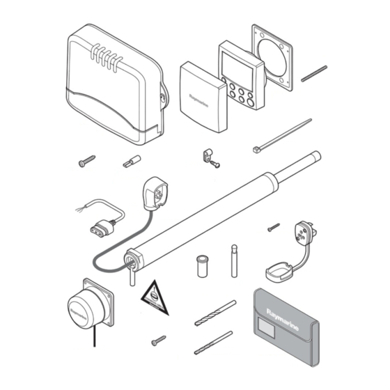
SmartPilot X-5 Tiller & GP Tiller Installation & Setup Guide 1.4 Equipment & Tools Before you begin ensure you have all the necessary components and tools to install your system. Parts supplied Finger Nut (x2) Stud (x2) Panel Seal SmartPilot ST6002 Course Controller... -
Page 13: Tools And Equipment Not Supplied
Chapter 1: Installation and system overviews Tools and equipment NOT supplied You will need to supply the following equipment and tools: Tools: • Drill • 2.5 mm ( "), 6 mm(1/4"), 12.5 mm (1/2"), 18 mm ( ") drill bits •... -
Page 14: Create A Schematic Diagram
SmartPilot X-5 Tiller & GP Tiller Installation & Setup Guide Part Number Description D029 Pedestal Socket 76 mm (3") D030 Pedestal Socket 89 mm (3.5") D031 Cantilever Socket D159 Tiller Bracket 102 mm (4") D160 Tiller Bracket 127 mm (5") 1.5 Create a schematic diagram As part of the preparation for installing your SPX-5 Tiller system, we recommend that you create a schematic diagram representing the system you want to install. -
Page 15: Chapter 2:Installing The System
Switch off the power supply before you start installing this product. EMC installation guidelines Raymarine equipment and accessories conform to the appropriate Electromagnetic Compatibility (EMC) regulations. This minimizes electromagnetic interference between equipment, which could otherwise affect the performance of your system. -
Page 16: Suppression Ferrites
Use only ferrites of the correct type, supplied by Raymarine authorized dealers. Connections to other equipment If Raymarine equipment is to be connected to other equipment using a cable not supplied by Raymarine, a Raymarine suppression ferrite MUST always be attached to the cable near the Raymarine unit. -
Page 17: Spx-5 Tiller System Course Computer
Chapter 2: Installing the system CAUTION: Power cable Using an incorrect size of power cable could reduce the power supplied to the drive unit and therefore cause your SPX-5 Tiller system to malfunction. Ensure the correct cable size is used. If in doubt, use a heavier gauge cable. - Page 18 SmartPilot X-5 Tiller & GP Tiller Installation & Setup Guide 237 mm (9.33 in) 56 mm (2.2 in) D10375-1...
-
Page 19: Connection Overview
Chapter 2: Installing the system X-5 connection overview The X-5 course computer provides the following system connections. SeaTalk fuse Power fuse Note: Spare fuses (2 A) (15A) are located in the connector cover Fluxgate NMEA 0183 SeaTalk Power RF ground compass inputs input/ouput inputs/outputs... - Page 20 SmartPilot X-5 Tiller & GP Tiller Installation & Setup Guide Use the following table to determine the required position for your vessel. Drive pin Max degrees of Rate of helm Force at rudder distance from helm (with pilot change rudder stock engaged) 457 mm (18”) 31º...
-
Page 21: Step 1 - Mount The Tiller Drive
Chapter 2: Installing the system If you need to adapt the standard installation, refer to Adapting the installation on page 16 for adaptation options. Step 1 - Mount the Tiller Drive Use this procedure when neither accessories or adaptation of the drive unit position are required. - Page 22 SmartPilot X-5 Tiller & GP Tiller Installation & Setup Guide 12.5 mm (1/2 in) 25mm (1.0 in) Two part epoxy adhesive to fix mounting socket in place...
-
Page 23: Step 2 - Install The Socket
Chapter 2: Installing the system Step 2 - Install the socket Cable requirement CAUTION: Power cable Using an incorrect size of power cable could cause your SPX-5 Tiller system to malfunction and reduce the power supplied to the drive unit. Ensure the correct size is used. If in doubt, use a heavier gauge cable. -
Page 24: Adapting The Installation
SmartPilot X-5 Tiller & GP Tiller Installation & Setup Guide 2.5 Adapting the installation Note: Accessories page 5 Refer to for details of parts available to adapt your installation. Pushrod extension Referring to the following illustration, if dimension C is greater than 620 mm (24.5”), use a pushrod extension. -
Page 25: Pedestal Socket
Chapter 2: Installing the system To use the cantilever socket: 1. Use a hacksaw to cut the rod to length L = F - 635 mm (25”). 2. Assemble the mounting ring, rod and socket. 3. With the drive horizontal mark the location of the mounting ring and its holes. 4. -
Page 26: Tiller Brackets
SmartPilot X-5 Tiller & GP Tiller Installation & Setup Guide Tiller brackets If the tiller is higher or lower than the mounting socket, use a tiller bracket to vary the tiller pin height so the drive is horizontal. If the drive is below the tiller, bracket size equals dimension D. If the drive is above the tiller;... -
Page 27: Connecting Power & Drive Cables To The Course Computer
Chapter 2: Installing the system 3. Drill two 6 mm (1/4”) diameter clearance holes through the center line of the tiller at the positions marked. 4. Attach the tiller bracket using two 6 mm (1/4“) diameter bolts, nuts and washers. 5. -
Page 28: Connection Procedure
SmartPilot X-5 Tiller & GP Tiller Installation & Setup Guide Connection procedure Brown Blue Black Distribution Drive unit panel Fuse or circuit breaker Power supply D10622-1 At the Course Computer, locate the free ends of the power cable from the distribution panel and Tiller Drive cable. -
Page 29: Fluxgate Compass
Compass mounting Location To achieve the best performance, mount your compass: • With the Raymarine logo facing the bow. • As close as possible to the boat’s pitch and roll center. • At least 2ft 6 in (0.8 m) away from your boat’s steering compass to avoid deviation of both compasses. -
Page 30: Compass Connection
SmartPilot X-5 Tiller & GP Tiller Installation & Setup Guide D10618-1 Compass connection Route the compass cable to the Course Computer, securing it at regular intervals with suitable cable clips/ties. Connect to the Course Computer as in the following illustration. Screen Green Yellow... -
Page 31: Pilot Controller
Chapter 2: Installing the system 2.8 Pilot Controller Fitting The ST6002 Pilot Controller is supplied with an 9 m cable for connection to the SeaTalk bus. Ensure that your mounting location is within 9 m of a suitable connection point. You may purchase a longer cable if required. Fit the controller in accordance with the separate instruction leaflet. - Page 32 SmartPilot X-5 Tiller & GP Tiller Installation & Setup Guide SeaTalk power supplied by Course Computer Course Computer Pilot Controller SeaTalk instruments Yellow Screen SeaTalk D10644-1 SeaTalk power supplied externally Course Computer Pilot Controller SeaTalk instruments SeaTalk SeaTalk Yellow Screen SeaTalk 12 V power supply (via breaker/fuse) Do not connect red wire...
-
Page 33: Connect To Ground
Chapter 2: Installing the system 2.9 Connect to ground CAUTION: Grounding SPX-5 Tiller system ground MUST be connected to ship’s ground. Failure to connect to ship’s ground may cause it, or other on-board electronics to malfunction. To ground your SPX-5 Tiller system: •... -
Page 34: Optional Connections
SmartPilot X-5 Tiller & GP Tiller Installation & Setup Guide 2.10Optional connections Rudder reference An optional rudder reference transducer is available to provide an accurate display of the rudder angle. If you have the optional rudder reference transducer, connect it to the course computer as shown. -
Page 35: Seatalkng Connections
Chapter 2: Installing the system SeaTalk Connections To connect your autopilot to a SeaTalk backbone, use a dedicated spur cable. Spur cables are available from your Raymarine dealer, as follows: Part number SeaTalk spur cable length 1 ft 3 in (400 mm) -
Page 36: Nmea 0183 Equipment
NMEA 0183 / Connecting other manufacturers’ equipment • When connecting Raymarine equipment to other equipment using a non- Raymarine cable, you MUST attach an appropriate suppression ferrite to the cable near to the Raymarine unit. • When connecting third party equipment refer to the manufacturer’s instructions for cable details. -
Page 37: Final Checks
Chapter 2: Installing the system 2.11Final checks When you have completed all necessary installation procedures, but before you apply power to the system, ensure all equipment and connections are properly secured. Secure all cables To prevent strain on the connector blocks, secure the cables to the Course Computer with cable ties as shown below. - Page 38 SmartPilot X-5 Tiller & GP Tiller Installation & Setup Guide...
-
Page 39: Chapter 3:Commissioning & Setup
Chapter 3: Commissioning & setup This chapter describes the commissioning and setup procedures for your Raymarine SPX-5 Tiller system. Requirement The commissioning procedures are mandatory and must be carried out after installation, before the SPX-5 Tiller system is used to steer the boat. -
Page 40: Check Seatalk And Nmea 0183 Connections
SmartPilot X-5 Tiller & GP Tiller Installation & Setup Guide TRUE D10524-1 Check SeaTalk and NMEA 0183 connections SeaTalk instruments If you have connected the Pilot Controller to other SeaTalk instruments or controllers: 1. Select display lighting level 3 (LAMP 3) on one of the other SeaTalk instruments or controllers. -
Page 41: Setting The Vessel And Drive Type
Chapter 3: Commissioning & setup D10646-1 4. If the rudder moves to port or the rudder drives hard over: Press standby. ii. Turn off the power. iii. Reverse the motor wires connected to the SPX-5 Tiller system computer. iv. Switch on the power and re-check. Note: If the rudder overshoots and has to drive back or starts to hunt back and forth, increase page 54... -
Page 42: Set The Vessel Type
SmartPilot X-5 Tiller & GP Tiller Installation & Setup Guide Set the vessel type When you select a vessel type, the SPX-5 Tiller system automatically selects appropriate default values for various other calibration settings. These default values are listed on page 58 . To setup the vessel type, enter Dealer calibration then: 1. -
Page 43: Save The New Settings
Chapter 3: Commissioning & setup Save the new settings When you have adjusted the above settings hold down standby for two seconds, to Standby mode save your changes, leave Dealer calibration and return to the Seatrial calibration When you have completed the dockside checks, carry out a Seatrial calibration, to calibrate the compass and set up the autopilot steering characteristics. - Page 44 SmartPilot X-5 Tiller & GP Tiller Installation & Setup Guide 2. Use disp to move through the Seatrial calibration items until you see SWING COMPASS 2 sec D10541-1 Note: If you cannot access Seatrial calibration, you need to disable the calibration lock. This can page 52 be found in Dealer calibration (see 3.
-
Page 45: Aligning The Compass Heading
Chapter 3: Commissioning & setup Aligning the compass heading Once the deviation is displayed, press disp to move to the Heading Alignment (ALIGN HDG) page, then: 1. Manually steer the boat on a steady course at a speed sufficient to hold the course. -
Page 46: Autolearn
SmartPilot X-5 Tiller & GP Tiller Installation & Setup Guide AutoLearn WARNING: Ensure there is enough clear sea space The AutoLearn process takes the boat through a number of maneuvers, which can result in sudden, sharp turns, especially when the AutoLearn function is run on more maneuverable boats. - Page 47 Chapter 3: Commissioning & setup Enter Seatrial calibration 2 sec Prepare for AutoLearn • steer straight ahead at cruising speed (planing boats – just on the plane) • head into wind and waves AutoLearn in progress CHECK! Start AutoLearn Before proceeding, ensure you have sufficient clear sea space D10545-1...
-
Page 48: Commissioning Complete
SmartPilot X-5 Tiller & GP Tiller Installation & Setup Guide Boat completes AutoLearn AutoLearn successful Note: If you see a After LRN FAIL message, 7 to 27 press disp to return to steps the AUTOLEARN screen then repeat from Step 2 If you need to cancel the AutoLearn, press Save new settings •... -
Page 49: Response Level
Chapter 3: Commissioning & setup Over time you may wish to repeat these adjustments using a range of sea conditions and headings to achieve optimum all-round performance for your particular vessel and preferences. Adjust these settings when motoring your boat at cruising speed. Response level The principal method of adjusting the performance of an SPX-5 Tiller system is by changing the response level. -
Page 50: Counter Rudder
SmartPilot X-5 Tiller & GP Tiller Installation & Setup Guide • If the rudder gain is too low, the boat’s performance will be sluggish – it will take a long time to make the 40° turn and there will be no overshoot (B below). Correct this understeer by increasing the rudder gain setting. -
Page 51: Autotrim
Chapter 3: Commissioning & setup 3. Press and hold standby for 2 seconds to save the changes. 4. Press auto to check the SPX-5 Tiller system performance in Auto mode. AutoTrim You may also wish to adjust the AutoTrim setting. AutoTrim determines how quickly the SPX-5 Tiller system applies ‘standing helm’... - Page 52 SmartPilot X-5 Tiller & GP Tiller Installation & Setup Guide...
-
Page 53: Chapter 4:Spx-5 Tiller System Settings
Chapter 4: SPX-5 Tiller system settings 4.1 Introduction This chapter describes the SPX-5 Tiller system calibration settings and the factory default settings. The calibration settings can be adjusted to best suit your operating requirements, but as many will have been adjusted to optimum values when commissioning the system, they should not require further change. -
Page 54: Accessing The Calibration Modes
SmartPilot X-5 Tiller & GP Tiller Installation & Setup Guide Accessing the Calibration modes Accessing Calibration Modes 2 seconds 2 seconds (saves changes) Calibration Modes to enter display calibration mode to enter user calibration mode to enter seatrial calibration mode CAL ? to enter dealer calibration mode... -
Page 55: Display Calibration
Chapter 4: SPX-5 Tiller system settings 4.2 Display calibration Display calibration provides settings to adjust the information displayed on the Pilot Controller. Accessing Display Calibration 2 seconds (save changes) Display Calibration To adjust values The RUDD BAR parameters are adjustable only if the rudder reference transducer option is fitted Data pages Press disp... -
Page 56: Setting Up Data Pages
SmartPilot X-5 Tiller & GP Tiller Installation & Setup Guide The default data page settings are: Data Page Default Setting XTE (Cross Track Error) BTW (Bearing to Waypoint) - see Note below DTW (Distance to Waypoint) - see Note below RESPONSE Setting up data pages Remaining pages... -
Page 57: User Calibration
Chapter 4: SPX-5 Tiller system settings Available Data Pages Displayed as Bearing to Waypoint Rudder Gain RUDD GAIN Response RESPONSE Watch WATCH - used to control the Watch timer Universal Time Coordinated Note: There are 3 depth pages (meters, feet and fathoms) and 2 water temperature pages (°C and °F). -
Page 58: Autotack
SmartPilot X-5 Tiller & GP Tiller Installation & Setup Guide AutoTack The AutoTack angle is not adjustable. The apparent wind angle when AutoTack is initiated, is mirrored the other side of the wind, on the opposite tack. Gybe inhibit With gybe inhibit on: •... -
Page 59: Dealer Calibration
Chapter 4: SPX-5 Tiller system settings Screen Text Options RESPONSE Range = 1 to 9 Level 1 to 3 minimizes the amount of pilot activity. This conserves power, but may compromise short-term course-keeping accuracy. Level 4 to 6 should give good course keeping with crisp, well con- trolled turns under normal operating conditions Level 7 to 9 gives the tightest course keeping and greatest rudder activity (and power consumption). -
Page 60: Seatrial Calibration Lock
SmartPilot X-5 Tiller & GP Tiller Installation & Setup Guide Accessing Dealer Calibration 2 seconds (saves changes) Dealer Calibration To adjust values To exit & save changes 2 seconds D10603-1 Seatrial calibration lock This screen controls the access to Seatrial calibration. Options CAL LOCK OFF Calibration lock off –... -
Page 61: Drive Type
Chapter 4: SPX-5 Tiller system settings The correct setting for the SPX-5 Tiller system is SAIL BOAT. This should be set when commissioning the SPX-5 Tiller system. Drive type The drive type setting controls how the SPX-5 Tiller system drives the steering system. -
Page 62: Rudder Damping
SmartPilot X-5 Tiller & GP Tiller Installation & Setup Guide The default counter rudder gain is set during the initial seatrial, as part of the AutoLearn process (see page 42 ). Screen Text Range COUNT RUD 1 to 9 (Do NOT set to 0) Rudder damping If the SPX-5 Tiller system ‘hunts’... -
Page 63: Turn Rate Limit
Chapter 4: SPX-5 Tiller system settings Screen Text Options RESPONSE Range = 1 to 9 Level 1 to 3 minimizes the amount of pilot activity. This conserves power, but may compromise short-term course-keeping accuracy Level 4 to 6 should give good course keeping with crisp, well con- trolled turns under normal operating conditions Level 7 to 9 gives the tightest course keeping and greatest rudder activity (and power consumption). -
Page 64: Autotack Angle
SmartPilot X-5 Tiller & GP Tiller Installation & Setup Guide AutoTack angle The AutoTack angle is not adjustable. The apparent wind angle when AutoTack is initiated, is mirrored the other side of the wind, on the opposite tack. Gybe inhibit With gybe inhibit on: •... -
Page 65: Cruise Speed
CAUTION: Losing settings at system reset Do NOT carry out a System RESET unless advised to do so by a Raymarine dealer. If you complete a reset you will lose the SPX-5 Tiller system calibration settings. You will then need to repeat the SPX-5 Tiller system commissioning process. -
Page 66: System Defaults
SmartPilot X-5 Tiller & GP Tiller Installation & Setup Guide To carry out a system reset: 1. Select the System reset (RESET) screen in Dealer calibration. 2. Press then press AUTO. 3. The screen will then show an ARE YOU SURE message: auto •... -
Page 67: Appendix 1:Nmea 0183 Sentences
Appendix 1: NMEA 0183 sentences The SPX-5 Tiller Course Computer computer supports the following NMEA0183 sentences. NMEA0183 to Course Computer Header Data in Cross track error, bearing to waypoint, waypoint number Bearing to waypoint, distance to waypoint, waypoint number, time Latitude/longitude, time Heading Apparent wind angle, apparent wind speed... - Page 68 SmartPilot X-5 Tiller & GP Tiller Installation & Setup Guide...
-
Page 69: Appendix 2:Spx-5 Tiller System Specifications
Fluxgate Compass, NMEA 0183 v3.01, SeaTalk (x2), SeaTalk power Outputs NMEA 0183 v3.01, SeaTalk (x2), drive motor, drive clutch Raymarine drive compatibility: ST4000 Tiller Drive (standard and GP) (as supplied with product) ST4000 Wheel Drive Drive motor output: Continuous 5 A at nominal 12 V... -
Page 70: Tiller Drive
• Temperature range -20°C to 50°C (-4°F to 122°F) • Relative humidity limit Inputs Drive power from compatible Course Computer. Servicing Raymarine approved service at 1000 hrs intervals EMC compliance: Europe 2004/108/EC (EMC) Australia and New Zealand: C-Tick, Compliance Level 2... -
Page 71: Pilot Controller (St6002)
SPX-5 Tiller system specifications Pilot Controller (ST6002) Nominal supply voltage: 12 V DC via SeaTalk Operating voltage range: 10 V to 15 V DC Current consumption (in Standby 60 mA (less than 200 mA with full lighting) mode) Operating temperature: 0 °C to +70 °C (32 °F to 158 °F) Water protection: waterproof to CFR46... - Page 72 SmartPilot X-5 Tiller & GP Tiller Installation & Setup Guide...
-
Page 73: Index
Index Dealer calibration (continued) Accessing calibration modes response level Adapting the installation rudder damping AutoLearn rudder gain AutoTack rudder limit AutoTrim seatrial calibration lock system reset turn rate limit Calibration modes vessel type Cantilever socket wind type Certified installation WindTrim Checking system operation Display calibration Commissioning... - Page 74 SmartPilot X-5 Tiller & GP Tiller Installation & Setup Guide Setup (continued) Off course warning angle latitude off course warning angle power steer (joystick) mode Parts supplied response level Pedestal socket rudder damping Pilot Controller rudder gain connecting rudder indicator alignment SeaTalk power NOT supplied by Course rudder limits Computer...
- Page 75 Tiller Drive socket template Tiller drive - socket template Drill 2.5 mm (3/32 inch) Drill 18 mm (23/32 inch) diameter hole (2 positions) diameter hole...
Need help?
Do you have a question about the SmartPilot X5 and is the answer not in the manual?
Questions and answers