Juniper J-series Services Router J2350 Hardware Manual
J-series services routers software with enhanced services
Hide thumbs
Also See for J-series Services Router J2350:
- User manual (675 pages) ,
- Getting started manual (332 pages) ,
- Quick start quide (26 pages)
Table of Contents
Advertisement
Quick Links
Download this manual
See also:
User Manual
Advertisement
Table of Contents

Related Manuals for Juniper J-series Services Router J2350


Summary of Contents for Juniper J-series Services Router J2350
- Page 1 JUNOS® Software with Enhanced Services Hardware Guide for J-series Services Routers Release 9.2 Juniper Networks, Inc. 1194 North Mathilda Avenue Sunnyvale, California 94089 408-745-2000 www.juniper.net Part Number: 530-025664-01, Revision 1...
- Page 2 Products made or sold by Juniper Networks or components thereof might be covered by one or more of the following patents that are owned by or licensed to Juniper Networks: U.S. Patent Nos. 5,473,599, 5,905,725, 5,909,440, 6,192,051, 6,333,650, 6,359,479, 6,406,312, 6,429,706, 6,459,579, 6,493,347, 6,538,518, 6,538,899, 6,552,918, 6,567,902, 6,578,186, and 6,590,785.
- Page 3 AND (B) YOU MAY CONTACT JUNIPER NETWORKS REGARDING LICENSE TERMS. 1. The Parties. The parties to this Agreement are Juniper Networks, Inc. and its subsidiaries (collectively “Juniper”), and the person or organization that originally purchased from Juniper or an authorized Juniper reseller the applicable license(s) for use of the Software (“Customer”) (collectively, the “Parties”).
- Page 4 (“GPL”) or the GNU Library General Public License (“LGPL”)), Juniper will make such source code portions (including Juniper modifications, as appropriate) available upon request for a period of up to three years from the date of distribution. Such request can be made in writing to Juniper Networks, Inc., 1194 N.
- Page 5 Abbreviated Table of Contents About This Guide Part 1 Services Router Overview Chapter 1 Overview of Services Routers Chapter 2 J-series Services Router Hardware Features Chapter 3 PIM Overview Part 2 Installing a Services Router Chapter 4 Preparing for Router Installation Chapter 5 Installing and Connecting a Services Router Chapter 6...
- Page 6 JUNOS Software with Enhanced Services Hardware Guide...
-
Page 7: Table Of Contents
Table of Contents About This Guide Objectives ...xv Audience ...xv Supported Routing Platforms ...xvi How to Use This Manual ...xvi Document Conventions ...xviii JUNOS Software Documentation for J-series Services Routers and SRX-series Services Gateways ...xx Documentation Feedback ...xxi Requesting Technical Support ...xxii Part 1 Services Router Overview Chapter 1... - Page 8 JUNOS Software with Enhanced Services Hardware Guide J2320 and J2350 External Compact Flashes ...18 J2320 Power System ...18 J2350 Power System ...18 J2320 and J2350 Cooling System ...19 J4350 and J6350 Services Router Hardware Features ...20 J4350 and J6350 Chassis ...21 J4350 and J6350 Midplane ...25 J4350 and J6350 Routing Engine Hardware ...25 J4350 and J6350 Boot Devices ...25...
- Page 9 Part 2 Installing a Services Router Chapter 4 Preparing for Router Installation General Site Guidelines ...63 Rack Requirements ...64 Rack Size and Strength for J2320 and J2350 Routers ...64 Rack Size and Strength for J4350 and J6350 Routers ...65 Connection to Building Structure ...65 Router Environmental Tolerances ...66 Fire Safety Requirements ...66 Fire Suppression ...66...
- Page 10 JUNOS Software with Enhanced Services Hardware Guide Loopback Address ...94 Built-In Ethernet Interface Address ...94 Management Access ...95 Before You Begin ...95 Connecting to a Services Router ...96 Connecting to the J-Web Interface ...97 Connecting to the CLI Locally ...98 Connecting to the CLI Remotely ...100 Configuring Basic Settings with J-Web Quick Configuration ...103 Configuring Basic Settings Using the CLI Configuration Wizard ...106...
- Page 11 Why Compact Flash Recovery Might Be Necessary ...164 Recommended Recovery Hardware and Software ...164 Configuring Internal Compact Flash Recovery ...165 Contacting the Juniper Networks Technical Assistance Center ...167 Chapter 10 Contacting Customer Support and Returning Hardware Locating Component Serial Numbers ...169 J2320 and J2350 Chassis Serial Number and Agency Labels ...170...
- Page 12 JUNOS Software with Enhanced Services Hardware Guide Part 4 J-series Requirements and Specifications Chapter 11 Network Cable Specifications and Connector Pinouts Serial PIM Cable Specifications ...179 RS-232 DTE Cable Pinout ...180 RS-232 DCE Cable Pinout ...181 RS-422/449 (EIA-449) DTE Cable Pinout ...181 RS-422/449 (EIA-449) DCE Cable Pinout ...183 EIA-530A DTE Cable Pinout ...184 EIA-530A DCE Cable Pinout ...185...
- Page 13 Installation Safety Guidelines and Warnings ...216 Laser and LED Safety Guidelines and Warnings ...221 Maintenance and Operational Safety Guidelines and Warnings ...225 Agency Approvals ...232 Compliance Statements for Environmental Requirements ...233 Lithium Battery ...233 Compliance Statements for EMC Requirements ...233 Canada ...233 European Community ...235 Japan ...236...
- Page 14 JUNOS Software with Enhanced Services Hardware Guide Table of Contents...
-
Page 15: About This Guide
About This Guide This preface provides the following guidelines for using the JUNOS Software with Enhanced Services Hardware Guide: Objectives on page xv Audience on page xv Supported Routing Platforms on page xvi How to Use This Manual on page xvi Document Conventions on page xviii JUNOS Software Documentation for J-series Services Routers and SRX-series Services Gateways on page xx... - Page 16 JUNOS Software with Enhanced Services Hardware Guide Personnel operating the equipment must be trained and competent; must not conduct themselves in a careless, willfully negligent, or hostile manner; and must abide by the instructions provided by the documentation. Supported Routing Platforms This manual describes features supported on J-series Services Routers running JUNOS software with enhanced services and SRX-series services gateways running JUNOS software.
- Page 17 Table 1: Tasks and Related Documentation (continued) Task Configuring device interfaces Deployment Planning and Configuration Understanding and gathering information required to design network firewalls and IPsec VPNs Implementing a JUNOS software with enhanced services firewall from a sample scenario Implementing a policy-based IPsec VPN from a sample scenario Security Configuration Configuring and managing the following security services:...
-
Page 18: Document Conventions
JUNOS Software with Enhanced Services Hardware Guide Table 1: Tasks and Related Documentation (continued) Task Administering user authentication and access Monitoring the device, routing protocols, and routing operations Configuring and monitoring system alarms and events, real-time performance (RPM) probes, and performance Monitoring the firewall and other security-related services Managing system log files Upgrading software... - Page 19 Table 3: Text and Syntax Conventions (continued) Convention Fixed-width text like this Italic text like this Italic text like this Plain text like this < > (angle brackets) | (pipe symbol) # (pound sign) [ ] (square brackets) Indention and braces ( { } ) ;...
-
Page 20: Services Gateways
JUNOS Software with Enhanced Services Hardware Guide Table 3: Text and Syntax Conventions (continued) Convention > (bold right angle bracket) JUNOS Software Documentation for J-series Services Routers and SRX-series Services Gateways Table 4 on page xx lists the software manuals and release notes for J-series Services Routers running JUNOS software with enhanced services and SRX-series services gateways running JUNOS software. -
Page 21: Documentation Feedback
Table 4: JUNOS Software Documentation for J-series Services Routers and SRX-series Services Gateways (continued) Book J-series Services Routers Only JUNOS Software with Enhanced Services Design and Implementation Guide JUNOS Software with Enhanced Services Quick Start JUNOS Software with Enhanced Services Hardware Guide JUNOS Software with Enhanced Services Migration Guide... -
Page 22: Requesting Technical Support
7 days a week, 365 days a year. Self-Help Online Tools and Resources For quick and easy problem resolution, Juniper Networks has designed an online self-service portal called the Customer Support Center (CSC) that provides you with the following features:... - Page 23 About This Guide For international or direct-dial options in countries without toll-free numbers, visit us at http://www.juniper.net/support/requesting-support.html xxiii Requesting Technical Support...
- Page 24 JUNOS Software with Enhanced Services Hardware Guide xxiv Requesting Technical Support...
-
Page 25: Services Router Overview
Part 1 Services Router Overview Overview of Services Routers on page 3 J-series Services Router Hardware Features on page 7 PIM Overview on page 35 Services Router Overview... - Page 26 JUNOS Software with Enhanced Services Hardware Guide Services Router Overview...
-
Page 27: Overview Of Services Routers
Quick Configuration wizards simplify basic configuration and minimize the risk of operator error. JUNOS command-line interface—A Juniper Networks command shell that runs on top of a UNIX-based operating system kernel. The CLI is a straightforward command interface. On a single line, you type commands that are executed when you press the Enter key. - Page 28 JUNOS Software with Enhanced Services Hardware Guide supply, an external compact flash and two universal serial bus (USB) ports for external storage, and an optional Crypto Accelerator Module. J2320 routers ordered with the optional Crypto Accelerator Module come standard with 1 GB of memory, while those ordered without the Crypto Accelerator Module come standard with 256 MB of memory.
-
Page 29: J4350 Services Router Overview
Dual-Port T1 PIM Dual-Port Channelized T1/E1/ISDN PRI PIM 4-port ISDN BRI S/T or U PIM ADSL 2/2+ Annex A PIM (1 port) ADSL 2/2+ Annex B PIM (1 port) G.SHDSL PIM (2 ports) WXC Integrated Services Module J4350 Services Router Overview The J4350 Services Router is designed primarily for regional and branch offices. -
Page 30: J6350 Services Router Overview
JUNOS Software with Enhanced Services Hardware Guide G.SHDSL PIM (2 ports) WXC Integrated Services Module J6350 Services Router Overview The J6350 Services Router is designed primarily for regional and central offices. It has a chassis that is 2 U (rack units) in size with an optional redundant AC or DC power supply, up to 2 GB of memory, and two universal serial bus (USB) ports for external storage. -
Page 31: Chapter 2 J-Series Services Router Hardware Features
Chapter 2 J-series Services Router Hardware Features J-series Services Routers running JUNOS software with enhanced services have chassis that are similar but with important differences. J2320, J2350, and J4350 routers have a single nonredundant power supply and an optional Crypto Accelerator Module. J6350 routers have redundant power supplies and a standard Crypto Accelerator Module. - Page 32 JUNOS Software with Enhanced Services Hardware Guide J2320 and J2350 Chassis The J2320 and J2350 chassis is a rigid sheet metal structure that houses all the other router components (see Figure 1 on page 8 through Figure 7 on page 11). The chassis can be installed in many types of racks or cabinets.
-
Page 33: J-Series Services Router Hardware Features
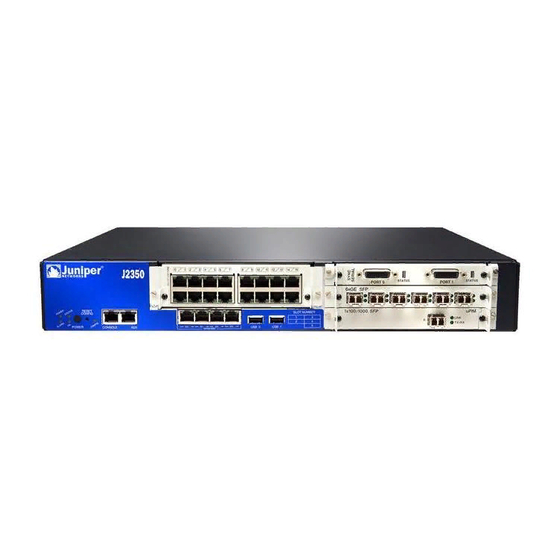
Chapter 2: J-series Services Router Hardware Features Figure 2: Front of J2350 Chassis Figure 3: Rear of J2320 Chassis Figure 4: Rear of J2350 AC-Powered Chassis J2320 and J2350 Services Router Hardware Features... - Page 34 JUNOS Software with Enhanced Services Hardware Guide Figure 5: Rear of J2350 DC-Powered Chassis Figure 6: J2320 Hardware Components J2320 and J2350 Services Router Hardware Features...
- Page 35 Figure 7: J2350 Hardware Components Table 5 on page 11 summarizes the physical specifications for the router chassis. Table 5: J2320 and J2350 Physical Specifications Description Value Chassis dimensions J2320 Services Router 1.75 in. (4.45 cm) high 17.51 in. (44.48 cm) wide—18.9 in. (48.01 cm) wide with mounting brackets attached 15.1 in.
-
Page 36: J2320 And J2350 Routing Engine Hardware
JUNOS Software with Enhanced Services Hardware Guide J2320 and J2350 Midplane The J2320 and J2350 midplane is located in the center of the chassis and forms the rear of the PIM card cage (see Figure 6 on page 10 and Figure 7 on page 11). You install the PIMs into the midplane from the front of the chassis. -
Page 37: J2320 And J2350 Front Panel
USB storage device Normally, a J2320 or J2350 Services Router boots from the internal compact flash. If the internal compact flash fails, the router attempts to boot from the external compact flash if it is installed. If the external compact flash is not present or fails, the router attempts to boot from the USB storage device. -
Page 38: Physical Interface Modules (Pims)
JUNOS Software with Enhanced Services Hardware Guide Console Port on page 17 AUX Port on page 17 USB Port on page 17 Physical Interface Modules (PIMs) Physical Interface Modules (PIMs) provide the physical connection to various network media types. For information about individual PIMs, see “Field-Replaceable PIMs”... -
Page 39: Alarm Led
After the router is powered on, status indicators—such as LEDs on the front panel show chassis power supply is functioning normally. Ignore error indicators that appear during the first 60 seconds. If you need to power off the router after the Routing Engine finishes booting, use the J-Web interface or the CLI to halt the Services Router first. -
Page 40: Reset Config Button
JUNOS Software with Enhanced Services Hardware Guide Table 8: J2320 and J2350 ALARM LED (continued) Color State Yellow On steadily Unlit For information about alarm conditions and corrective actions, see “Monitoring and Correcting Chassis Alarm Conditions” on page 157. For additional information, see the JUNOS Software Administration Guide. -
Page 41: Built-In Gigabit Ethernet Ports
Built-In Gigabit Ethernet Ports Four built-in Gigabit Ethernet ports provide LAN connections over copper interfaces to hubs, switches, local servers, and workstations. You can also designate an Ethernet port for management traffic. When configuring one of these ports, you use the interface name that corresponds to the port s location. -
Page 42: J2320 And J2350 External Compact Flashes
JUNOS Software with Enhanced Services Hardware Guide to receive any core files generated during a failure. For information about configuring a USB storage device, see the JUNOS Software Administration Guide. NOTE: For a list of supported USB storage devices, see the JUNOS Software with Enhanced Services Release Notes at J2320 and J2350 External Compact Flashes On J2320 and J2350 routers, an external compact flash, also known as removable... -
Page 43: J2320 And J2350 Cooling System
Chapter 2: J-series Services Router Hardware Features For information about site power preparations, see “Power Guidelines, Requirements, and Specifications” on page 67. For information about connecting the router to power and ground, see “Connecting Power” on page 84. NOTE: You cannot mix DC and AC power supplies in the same chassis. WARNING: DC-powered Services Routers are intended for installation only in a restricted access location. -
Page 44: J4350 And J6350 Services Router Hardware Features
JUNOS Software with Enhanced Services Hardware Guide Figure 11: Airflow Through the J2320 Chassis Figure 12: Airflow Through the J2350 Chassis J4350 and J6350 Services Router Hardware Features This section contains the following topics: J4350 and J6350 Chassis on page 21 J4350 and J6350 Midplane on page 25 J4350 and J6350 Routing Engine Hardware on page 25 J4350 and J6350 Boot Devices on page 25... - Page 45 J6350 Power System on page 31 J4350 and J6350 Cooling System on page 32 J4350 and J6350 Chassis The J4350 and J6350 chassis is a rigid sheet metal structure that houses all the other router components (see Figure 13 on page 22 through Figure 18 on page 24). The chassis can be installed in many types of racks or cabinets.
- Page 46 JUNOS Software with Enhanced Services Hardware Guide Figure 13: Front of J4350 and J6350 Chassis Figure 14: Rear of J4350 AC-Powered Chassis NOTE: The J4350 AC-powered chassis has a power switch and does not include a power supply LED (unlike the J6350 AC-powered chassis). Figure 15: Rear of J6350 AC-Powered Chassis J4350 and J6350 Services Router Hardware Features...
- Page 47 Chapter 2: J-series Services Router Hardware Features Figure 16: Rear of J4350 DC-Powered Chassis Figure 17: Rear of DC-Powered J6350 Chassis J4350 and J6350 Services Router Hardware Features...
- Page 48 JUNOS Software with Enhanced Services Hardware Guide Figure 18: J4350 and J6350 Hardware Components Table 11 on page 24 summarizes the physical specifications for the router chassis. Table 11: J4350 and J6350 Physical Specifications Description Value Chassis dimensions 3.44 in. (8.74 cm) high 17.44 in.
- Page 49 J4350 and J6350 Midplane The midplane is located in the center of the chassis and forms the rear of the PIM card cage (see Figure 18 on page 24). You install the PIMs into the midplane from the front of the chassis. Data packets are transferred across the midplane from the PIM to the Routing Engine, and from the Routing Engine across the midplane to the destination PIM.
-
Page 50: Physical Interface Modules (Pims)
JUNOS Software with Enhanced Services Hardware Guide J4350 and J6350 Front Panel The front panel of the Services Router (see Figure 19 on page 26) allows you to install or remove PIMs, view router status LEDs, access the console port, and perform simple control functions. -
Page 51: Status Led
Figure 20: Slot Number Diagram on Front Panel Gigabit Ethernet and 4-port Fast Ethernet ePIMs can be installed in high-speed slots only. High-speed slots are indicated by a black triangle containing an E in the front panel slot number diagram. On J4350 Services Routers, the high-speed slots are slot 3 and slot 6. - Page 52 JUNOS Software with Enhanced Services Hardware Guide off and on again, we recommend waiting a few seconds between shutting it down and powering it back up. Table 13 on page 28 describes the Table 13: STATUS LED Color State Green Blinking On steadily Blinking...
-
Page 53: Reset Config Button
HA LED The HA (high availability) LED is located in the front panel near the power status LED of the LED dashboard. The LED lights when the router starts, but otherwise remains unlit.Table 15 on page 29 describes the HA LED. Table 15: HA LED Color State... -
Page 54: Console Port
JUNOS Software with Enhanced Services Hardware Guide Table 16: Gigabit Ethernet Port LEDs (continued) Function Color Green TX/RX Unlit Console Port You can use the console port on the chassis front panel to connect to the Routing Engine through an RJ-45 serial cable. From the chassis console port, you can use the CLI to configure the router. -
Page 55: J6350 Power System
The J4350 AC-powered chassis has a power switch and does not include a power LED. The J4350 DC-powered chassis includes a power supply LED located to the upper right of the power supply connector. Table 17 on page 31 describes the power supply LED. -
Page 56: J4350 And J6350 Cooling System
JUNOS Software with Enhanced Services Hardware Guide Power supplies on J6350 Services Routers are hot-removable and hot-insertable. You can remove and replace a redundant power supply without powering down the router or disrupting the routing functions. To avoid electrical injury, carefully follow the instructions in “Replacing Power System Components”... - Page 57 Chapter 2: J-series Services Router Hardware Features Figure 21: Airflow Through the J4350 and J6350 Chassis J4350 and J6350 Services Router Hardware Features...
- Page 58 JUNOS Software with Enhanced Services Hardware Guide J4350 and J6350 Services Router Hardware Features...
-
Page 59: Chapter 3 Pim Overview
Chapter 3 PIM Overview J-series Services Routers accept Physical Interface Modules (PIMs) in the slots on the front of the chassis. CAUTION: PIMs are not hot-swappable. You must power off the Services Router before removing or inserting a PIM module. Ensure that the PIMs are installed in the router chassis before booting up the system. - Page 60 JUNOS Software with Enhanced Services Hardware Guide Table 18: PIM Terms Term Definition ADSL 2/2+ Annex A ITU-T Standard G.992.1 that defines how ADSL works over plain old telephone service (POTS) lines. ADSL 2/2+ Annex B ITU-T Standard G.992.1 that defines how ADSL works over Integrated Services Digital Network (ISDN) lines.
- Page 61 Table 18: PIM Terms (continued) Term Definition dialer filter Stateless firewall filter that enables dial-on-demand routing backup when applied to a physical ISDN interface and its dialer interface configured as a passive static route. The passive static route has a lower priority than dynamic routes. If all dynamic routes to an address are lost from the routing table and the router receives a packet for that address, the dialer interface initiates an ISDN backup connection and sends the packet over it.
-
Page 62: J2320 And J2350 Field-Replaceable Pim And Module Summary
JUNOS Software with Enhanced Services Hardware Guide Field-Replaceable PIMs PIMs are removable and insertable only when the Services Router is powered off. You install PIMs into slots in the router chassis. If a slot is not occupied by a PIM, a PIM blank panel must be installed to shield the empty slot and to allow cooling air to circulate properly through the router. - Page 63 Table 19: J2320 and J2350 Field-Replaceable PIM and Module Summary Supported Software Releases for This PIM 1-Port SFP, 6-Port SFP, Release 8.5 and later of JUNOS 8-Port, and 16-Port software with enhanced Gigabit Ethernet uPIMs services Dual-Port Serial PIM Release 8.5 and later of JUNOS software with enhanced services Dual-Port T1 or E1 PIM...
- Page 64 JUNOS Software with Enhanced Services Hardware Guide CAUTION: Do not install a combination of modules in a single chassis that exceeds the maximum power and heat capacity of the chassis. If J-series power management is enabled, PIMs and modules (PIMs or PIMs plus a WXC Integrated Services Module) that exceed the maximum power and heat capacity remain offline when the chassis is powered on.
- Page 65 Table 20: J4350 and J6350 Field-Replaceable PIM and Module Summary (continued) Supported Software Releases for This PIM T3 or E3 PIM Release 8.5 and later of JUNOS software with enhanced services Dual-Port Fast Ethernet Release 8.5 and later of JUNOS software with enhanced services 4-port Fast Ethernet...
- Page 66 JUNOS Software with Enhanced Services Hardware Guide Figure 22: 1-Port Gigabit Ethernet uPIM Figure 23: 6-Port Gigabit Ethernet uPIM The 8-port and 16-port Gigabit Ethernet uPIMs, shown in Figure 24 on page 42 and Figure 25 on page 42, have RJ-45 connectors. Figure 24: 8-Port Gigabit Ethernet uPIM Figure 25: 16-Port Gigabit Ethernet uPIM Field-Replaceable PIMs...
- Page 67 Features. Gigabit Ethernet uPIMs provide the following key features: The multiport uPIMs can be used as switches in the access layer (for connections to workstations and desktops). For more information, see the JUNOS Software Interfaces and Routing Configuration Guide. Link speed for 8-port and 16-port Gigabit Ethernet uPIMs is configurable to 10, 100, or 1000 Mbps, and transmission mode is configurable to half or full duplex.
- Page 68 JUNOS Software with Enhanced Services Hardware Guide Table 21: Gigabit Ethernet Port LEDs Function Link Activity (TX/RX) For alarms, see the configuring and monitoring alarms information in the JUNOS Software Administration Guide. Optical Interface Support. Table 22 on page 44 describes the optical interface support on the 1-port and 6-port Gigabit Ethernet uPIMs over single-mode fiber-optic (SMF) and multimode fiber-optic (MMF) cables.
- Page 69 Figure 26: Copper Gigabit Ethernet ePIM Figure 27: SFP Gigabit Ethernet ePIM Features. The Gigabit Ethernet ePIM provides the following key features: Autonegotiation through medium-dependent interface (MDI) and MDI crossover (MDI-X) support. Link speeds for the Copper Gigabit Ethernet ePIM are configurable to 10, 100, or 1000 Mbps, and transmission mode is configurable to half or full duplex.
- Page 70 JUNOS Software with Enhanced Services Hardware Guide Limitations. The Gigabit Ethernet ePIM has the following limitations: Gigabit Ethernet ePIMs do not support SNMP. Configure Gigabit Ethernet ePIM interfaces up to a maximum MTU size of 9018 bytes. Installation. You can install Gigabit Ethernet ePIMs in any high-speed slot as follows: J4350—Install up to two Gigabit Ethernet ePIMs in slots 3 and 6.
-
Page 71: Dual-Port Serial Pim
Table 24: Optical Interface Support for SFP Gigabit Ethernet ePIM (continued) Parameter Average launch power Receiver saturation Receiver sensitivity Dual-Port Serial PIM The Dual-Port Serial PIM (Figure 28 on page 47) provides a physical connection to serial network media types through two serial interface ports. Figure 28: Dual-Port Serial PIM The Dual-Port Serial PIM provides the following key features: Onboard network processor... -
Page 72: Dual-Port T1 Or E1 Pim
JUNOS Software with Enhanced Services Hardware Guide Table 25: Status LEDs for Serial Ports Color Green Unlit For alarms, see the configuring and monitoring alarms information in the JUNOS Software Administration Guide. Dual-Port T1 or E1 PIM The Dual-Port T1 PIM (Figure 29 on page 48) and Dual-Port E1 PIM (Figure 30 on page 48) provide a physical connection to T1 or E1 network media types. -
Page 73: Dual-Port Channelized T1/E1/Isdn Pri Pim
G.703, G.704, and G.706 E1 standards compliance Independent internal and external clocking system Loopback, bit error rate test (BERT), T1 facilities data link (FDL), and long buildout diagnostics For pinouts of cable connectors for T1 and E1 PIMs, see “E1 and T1 RJ-48 Cable Pinouts”... - Page 74 JUNOS Software with Enhanced Services Hardware Guide Figure 31: Channelized T1/E1/ISDN PRI PIM The Dual-Port Channelized T1/E1/ISDN PRI PIM provides the following key features: Onboard network processor Two-port channelization Interfaces that are software configurable as T1 or E1 channels or ISDN PRI B-channels Clear-channel, fractional, and channelized operation Lower latency due to the addition of a Freescale processor...
-
Page 75: T3 Or E3 Pim
Table 27: LEDs for Channelized T1/E1/ISDN PRI PIMs Label ONLINE STATUS For alarms, see the configuring and monitoring alarms information in the JUNOS Software Administration Guide. T3 or E3 PIM The T3 (also known as DS3) PIM (Figure 32 on page 51) and E3 PIM (Figure 33 on page 52) provide a physical connection to T3 or E3 network media types. - Page 76 JUNOS Software with Enhanced Services Hardware Guide Figure 33: E3 PIM The T3 and E3 PIMs provide the following key features: Onboard network processor Integrated DSU—Eliminates the need for a separate external device Subrate and scrambling options with support for major DSU vendors Independent internal and external clocking system Loopback (payload–supported only on T3 PIM, local, and remote), bit error rate test (BERT), and T3 far-end alarm and control (FEAC) diagnostics...
-
Page 77: Dual-Port Fast Ethernet Pim
Dual-Port Fast Ethernet PIM The Dual-Port 10/100-Mbps Fast Ethernet PIM (Figure 34 on page 53) has two physical Fast Ethernet ports. Figure 34: Fast Ethernet PIM The Dual-Port Fast Ethernet PIM provides the following key features: Onboard network processor Full-duplex and half-duplex modes Media access control (MAC) address filtering Autonegotiation through medium-dependent interface (MDI) and MDI crossover (MDI–X) support... -
Page 78: 4-Port Fast Ethernet Epim
JUNOS Software with Enhanced Services Hardware Guide 4-Port Fast Ethernet ePIM You can install 4-Port Fast Ethernet ePIMs in any of the high-speed slots, as follows: J4350—Install up to two 4-Port Fast Ethernet ePIMs in slots 3 and 6. J6350—Install up to four 4-Port Fast Ethernet ePIMs in slots 2, 3, 5, and 6. NOTE: For 4-port Fast Ethernet ePIMs, if you apply a CoS scheduler map on outgoing (egress) traffic, the router does not divide the bandwidth appropriately among the CoS queues. -
Page 79: 4-Port Isdn Bri Pims
Table 30: LEDs for 4-Port Fast Ethernet ePIM Label Color Link status (upper Green left) Unlit Link activity (upper Green right) Unlit For alarms, see the configuring and monitoring alarms information in the JUNOS Software Administration Guide. 4-Port ISDN BRI PIMs The 4-port ISDN BRI PIMs have four physical ports that support the ISDN BRI S/T (Figure 36 on page 55) or ISDN BRI U (Figure 37 on page 55) interface type. -
Page 80: Adsl Pim
JUNOS Software with Enhanced Services Hardware Guide Dial backup Dial-on-demand routing backup (floating static and dialer watch) For pinouts of cable connectors for ISDN PIMs, see “ISDN RJ-45 Connector Pinout” on page 195. To install or remove a PIM, see “Replacing a PIM” on page 120. ISDN LEDs indicate PIM and port status. - Page 81 Figure 38: ADSL 2/2+ Annex A PIM Figure 39: ADSL 2/2+ Annex B PIM The ADSL PIM provides the following key features: Onboard network processor ADSL, ADSL2, and ADSL2+ protocols on the same PIM “Dying gasp” notification Asynchronous Transfer Mode (ATM) Adaptation Layer 5 (AAL5) encapsulation For pinouts of cable connectors for ADSL PIMs, see “ADSL and G.SHDSL RJ-11 Connector Pinout”...
-
Page 82: G.shdsl Pim
JUNOS Software with Enhanced Services Hardware Guide For alarms, see the configuring and monitoring alarms information in the JUNOS Software Administration Guide. G.SHDSL PIM The G.SHDSL PIM (Figure 40 on page 58) provides symmetric high-speed digital subscriber line (SHDSL) physical interfaces to ATM network media types. The G.SHDSL PIM has two ports for ATM-over-SHDSL connections. - Page 83 Table 33: LEDs for G.SHDSL PIMs Label Color Green ONLINE Unlit Green STATUS For alarms, see the configuring and monitoring alarms information in the JUNOS Software Administration Guide. State Description On steadily Online with no alarms or failures. Disconnected Initialization of the PIM has failed. PIM is booting.
- Page 84 JUNOS Software with Enhanced Services Hardware Guide Field-Replaceable PIMs...
-
Page 85: Installing A Services Router
Part 2 Installing a Services Router Preparing for Router Installation on page 63 Installing and Connecting a Services Router on page 77 Establishing Basic Connectivity on page 91 Installing JUNOS Software with Enhanced Services on page 115 Installing a Services Router... - Page 86 JUNOS Software with Enhanced Services Hardware Guide Installing a Services Router...
-
Page 87: Preparing For Router Installation
Chapter 4 Preparing for Router Installation Before installing a J-series Services Router, make sure that your site has the proper operating environment and equipment. Use the checklist at the end of the chapter to help you prepare your site. This chapter discusses the following topics: General Site Guidelines on page 63 Rack Requirements on page 64 Router Environmental Tolerances on page 66... -
Page 88: Rack Requirements
JUNOS Software with Enhanced Services Hardware Guide Rack Requirements J-series Services Routers must be installed in a rack. Many types of racks are acceptable, including front-mount racks, four-post (telco) racks, and center-mount racks. The following sections describe rack requirements: Rack Size and Strength for J2320 and J2350 Routers on page 64 Rack Size and Strength for J4350 and J6350 Routers on page 65 Connection to Building Structure on page 65 Rack Size and Strength for J2320 and J2350 Routers... - Page 89 The J2320 chassis height of 1.75 in. (4.45 cm) equals 1 U. The J2350 chassis height of 2.61 in. (6.63 cm) equals 1.5 U. Each U is a standard rack unit defined in Cabinets, Racks, Panels, and Associated Equipment (document number EIA-310-D) published by the Electronics Industry Association.
-
Page 90: Router Environmental Tolerances
In addition, establish procedures to protect your equipment in the event of a fire emergency. Juniper Networks products must be installed in an environment suitable for electronic equipment. We recommend that fire suppression equipment be available... -
Page 91: Fire Suppression Equipment
NOTE: To keep warranties effective, do not use a dry chemical fire extinguisher to control a fire at or near a Juniper Networks router. If a dry chemical fire extinguisher is used, the unit is no longer eligible for coverage under a service agreement. -
Page 92: Signaling Limitations
JUNOS Software with Enhanced Services Hardware Guide Site Electrical Wiring Guidelines WARNING: Certain ports on the router are designed for use as intrabuilding (within-the-building) interfaces only (Type 2 or Type 4 ports as described in GR-1089-CORE cabling. To comply with NEBS requirements and protect against lightening surges and commercial power disturbances, the intrabuilding ports must not be metallically connected to interfaces that connect to the OSP or its wiring. -
Page 93: Router Power Requirements
CAUTION: To comply with intrabuilding lightning/surge requirements, intrabuilding wiring must be shielded, and the shield for the wiring must be grounded at both ends. Router Power Requirements Table 35 on page 69 and Table 36 on page 69 list the AC and DC power system electrical specifications for Services Routers. - Page 94 JUNOS Software with Enhanced Services Hardware Guide Detachable AC power cords, each 2.5 m (approximately 8 ft) long, are supplied with the Services Router. The appliance coupler at the female end of the cord inserts into the appliance inlet on the faceplate of the AC power supply. The coupler is type C19 as described by International Electrotechnical Commission (IEC) standard 60320.
-
Page 95: Dc Power, Connection, And Power Cable Specifications
For information about the AC power supply, see “J2320 Power System” on page 18, “J2350 Power System” on page 18, “J4350 Power System” on page 30 or “J6350 Power System” on page 31. To connect the power cord during initial installation, see “Connecting Power”... -
Page 96: Planning For Power Management
JUNOS Software with Enhanced Services Hardware Guide NOTE: Power cords and cables must not block access to router components or drape where people might trip on them. For information about the DC power supply, see “J2350 Power System” on page 18, “J4350 Power System”... - Page 97 Table 38: J-series PIM Power Consumption and Heat Dissipation Name Model Number 1-Port Gigabit JXU-SFP-S Ethernet uPIM 6-Port Gigabit JXU-6GE-SFP-S Ethernet uPIM 8-Port Gigabit JXU-8GE-TX-S Ethernet uPIM 16-Port Gigabit JXU-16GE-TX-S Ethernet uPIM 1-Port Copper JXE-1GE-TX-S Gigabit Ethernet ePIM 1-Port SFP Gigabit JXE-1GE-SFP-S Ethernet ePIM Dual-Port Serial...
-
Page 98: Network Cable Specifications
JUNOS Software with Enhanced Services Hardware Guide Table 38: J-series PIM Power Consumption and Heat Dissipation (continued) Name Model Number ADSL 2/2+ JX-1ADSL-B-S Annex B PIM (1 port, for ISDN) G.SHDSL PIM JX-2SHDSL-S (2-port two-wire mode or 1-port four-wire mode) WXC Integrated ISM-200–WXC Services Module... -
Page 99: Site Preparation Checklist
Site Preparation Checklist The checklist in Table 40 on page 75 summarizes the tasks you need to perform when preparing a site for Services Router installation. Table 40: Site Preparation Checklist Item or Task Verify that environmental factors such as temperature and humidity do not exceed router tolerances. - Page 100 JUNOS Software with Enhanced Services Hardware Guide Site Preparation Checklist...
-
Page 101: Installing And Connecting A Services Router
Chapter 5 Installing and Connecting a Services Router Make the appropriate preparations and verify the J-series equipment before installing a J-series Services Router and connecting it to a power source and the network. CAUTION: Do not install a combination of modules in a single chassis that exceeds the maximum power and heat capacity of the chassis. - Page 102 JUNOS Software with Enhanced Services Hardware Guide For J2320 and J2350 Services Routers—Number 2 Phillips screwdriver, and mounting screws appropriate for your rack. For J4350 and J6350 Services Routers—Mounting brackets and screws (provided), number 2 Phillips screwdriver, and mounting screws appropriate for your rack.
- Page 103 Installing J2320 and J2350 Routers WARNING: DC-powered Services Routers are intended for installation only in a restricted access location. You can center-mount or front-mount the J2320 and J2350 Services Routers in a rack. In general, a center-mount rack is preferable to a front-mount rack because the more even distribution of weight in the center-mount rack provides greater stability.
-
Page 104: Installing J4350 And J6350 Routers
JUNOS Software with Enhanced Services Hardware Guide Align the top hole in each mounting bracket with a hole in each rack rail as shown in Figure 43 on page 80 and Figure 44 on page 80, making sure the chassis is level. - Page 105 You can center-mount or front-mount the J4350 and J6350 Services Routers in a rack. In general, a center-mount rack is preferable to a front-mount rack because the more even distribution of weight in the center-mount rack provides greater stability. Many types of racks are acceptable, including four-post (telco) racks, enclosed cabinets, and open-frame racks.
- Page 106 JUNOS Software with Enhanced Services Hardware Guide Figure 46: Attaching the Center Screw to the Rack Lift the router and insert the larger elliptical openings in the mounting brackets onto the partially inserted screws so that the router is hanging from the two screws (see Figure 47 on page 82).
-
Page 107: Connecting Interface Cables To Services Routers
Figure 48: Completing the Installation Connecting Interface Cables to Services Routers You connect the interfaces installed in the Services Router to various network media. For more information about the network interfaces supported on the router, see the JUNOS Software Interfaces and Routing Configuration Guide. Have ready a length of the type of cable used by the interface, as specified in “Network Cable Specifications and Connector Pinouts”... -
Page 108: Connecting Power
JUNOS Software with Enhanced Services Hardware Guide For J2320 and J2350 Services Routers—The grounding cables must be, at minimum, 14 AWG single-strand wire cable. The grounding lug must be a ring-type, vinyl-insulated TV14-8R lug as shown in Figure 49 on page 85 and Figure 50 on page 86. - Page 109 With a Phillips screwdriver, remove the screw and washer from the PEM nuts at the grounding point on the rear of the chassis. Place the grounding lug at the other end of the cable over the grounding point, as shown in Figure 49 on page 85 through Figure 51 on page 86. Secure the cable lug to the grounding point, first with the washer, then with the screw.
-
Page 110: Connecting Dc Power
JUNOS Software with Enhanced Services Hardware Guide Figure 50: Connecting AC Power to the J2350 Services Router Figure 51: Connecting AC Power to the J4350 or J6350 Services Router Connecting DC Power CAUTION: If your J6350 Services Router includes an optional redundant DC power supply, connect each of the two power supplies to different input power sources. - Page 111 Attach an electrostatic discharge (ESD) grounding strap to your bare wrist, and connect the strap to the ESD point on the chassis. For more information about ESD, see “Preventing Electrostatic Discharge Damage” on page 201. Use a grounding cable to connect the router to earth ground: (For cable requirements, see “Chassis Grounding”...
- Page 112 JUNOS Software with Enhanced Services Hardware Guide overtighten. Apply between 8 lb-in. (0.9 Nm) and 9 lb-in. (1.02 Nm) of torque to the screw. Using the other removed screw, secure the negative (–) DC source power cable lug to the overtighten.
-
Page 113: Powering A Services Router On And Off
Figure 53: Connecting DC Power to the J4350 or J6350 Services Router Powering a Services Router On and Off To power on a Services Router, press the power button. The Routing Engine boots as the power supply completes its startup sequence. The startup and remains on steadily when the router is operating normally. - Page 114 JUNOS Software with Enhanced Services Hardware Guide Powering a Services Router On and Off...
-
Page 115: Establishing Basic Connectivity
Chapter 6 Establishing Basic Connectivity The JUNOS software is preinstalled on the Services Router. When the router is powered on, it is ready to be configured. If the router does not have a configuration from the factory or your service provider, you must configure the software to establish basic connectivity. -
Page 116: Router Identification
JUNOS Software with Enhanced Services Hardware Guide Table 41: Basic Connectivity Terms (continued) Term hostname loopback address Network Time Protocol (NTP) root user secure shell (SSH) Telnet Basic Connectivity Overview To connect your Services Router to the network and establish basic connectivity, you enter information about your network. - Page 117 router. To ensure basic security, you must define the root password during initial configuration. If a root password is not defined, you cannot commit configuration settings to take effect on the router. If you use a plain-text password, the router displays the password as an encrypted string so that users viewing the configuration cannot easily see the password.
-
Page 118: Backup Router
JUNOS Software with Enhanced Services Hardware Guide Backup Router You can specify a backup router to take over when the routing protocol process of the Services Router is not running, usually when the Services Router is booting, or if its routing protocol process has failed. Packets arriving at a Services Router in this situation are routed to the backup router. -
Page 119: Management Access
With the router temporarily acting as a DHCP server, you can manually configure it with the J-Web interface. Any DHCP client host, for example, a PC or laptop computer, directly connected to NOTE: The DHCP functionality for initial setup is different from the configurable DHCP server functionality of the Services Router during operation. -
Page 120: Connecting To A Services Router
JUNOS Software with Enhanced Services Hardware Guide Install the Services Router in its permanent location, as described in “Installing and Connecting a Services Router” on page 77. Gather the following information: Hostname for the router on the network Domain that the router belongs to on the network Password for the root user Time zone where the router is located IP address of an NTP server (if NTP is used to set the time on the router) -
Page 121: Connecting To The J-Web Interface
This section contains the following topics: Connecting to the J-Web Interface on page 97 Connecting to the CLI Locally on page 98 Connecting to the CLI Remotely on page 100 Connecting to the J-Web Interface If you plan to use the J-Web interface to configure the Services Router, you must connect through one of the built-in Ethernet management ports, as shown in Figure 54 on page 98 and Figure 55 on page 98. - Page 122 JUNOS Software with Enhanced Services Hardware Guide Figure 54: Connecting to the Gigabit Ethernet Port on J2320 and J2350 Routers Figure 55: Connecting to the Gigabit Ethernet Port on J4350 and J6350 Routers Connecting to the CLI Locally If you plan to use the CLI to configure the router, you must connect through the console port, as shown in Figure 56 on page 100 and Figure 57 on page 100.
- Page 123 To connect to the CLI using a local management device through the console port on the router: Turn off power to the router. Turn off the power to the management device, such as a PC or laptop computer, that you are using to access the CLI. Plug one end of the Ethernet cable supplied with your router into the RJ-45 to DB-9 serial port adapter supplied with your router (see Figure 57 on page 100).
-
Page 124: Connecting To The Cli Remotely
JUNOS Software with Enhanced Services Hardware Guide Figure 56: Connecting to the Console Port on J2320 and J2350 Routers Figure 57: Connecting to the Console Port on the J4350 and J6350 Routers Connecting to the CLI Remotely You can connect to the CLI from a remote location through two dial-up modems: a modem that is connected to the console port on the Services Router and a second modem connected to a remote management device. -
Page 125: Configuring The Modem At The Router End
This section contains the following topics: Configuring the Modem at the Router End on page 101 Connecting the Modem to the Console Port on page 102 Connecting to the CLI at the User End on page 102 Configuring the Modem at the Router End NOTE: These instructions use Hayes-compatible modem commands to configure the modem. - Page 126 JUNOS Software with Enhanced Services Hardware Guide Connecting the Modem to the Console Port NOTE: Most modems have an RS-232 DB-25 connector. You must separately purchase an adapter to connect your modem to the RJ-45 to DB-9 adapter and Ethernet cable supplied with the router.
-
Page 127: Configuring Basic Settings With J-Web Quick Configuration
COM port on the PC or laptop. To dial the modem that is connected to the console port on the router, enter ATDT remote-modem-number to the console port on the router is The router login prompt appears. Log in as the user must assign a root password before committing any configuration settings. - Page 128 JUNOS Software with Enhanced Services Hardware Guide To configure basic settings with J-Web Quick Configuration: If you have not already done so, connect a management device to the interface on port 0/0. For instructions, see “Connecting to the J-Web Interface” on page 97. If the Set Up Quick Configuration page is not displayed, select Configuration>Quick Configuration >Set Up.
- Page 129 Table 42: Set Up Quick Configuration Summary (continued) Field Function Time Time Zone Identifies the time zone that the router is located in. NTP Servers Specify an NTP server that the router can reach to synchronize the system time. Current System Time Synchronizes the system time with the NTP server, or manually set the system time and date.
-
Page 130: Configuring Basic Settings Using The Cli Configuration Wizard
JUNOS Software with Enhanced Services Hardware Guide Table 42: Set Up Quick Configuration Summary (continued) Field Function Allow Telnet Access Allows remote access to the router using Telnet. Allow JUNOScript Allows JUNOScript to access the router using over Clear-Text a protocol for sending unencrypted text over Access a TCP connection. -
Page 131: Using The Junos Software With Enhanced Services Configuration Wizard
Using the JUNOS Software with Enhanced Services Configuration Wizard Before you use the CLI configuration wizard, log in to the Services Router console as described in “Connecting to the CLI Locally” on page 98 or “Connecting to the CLI Remotely” on page 100 To invoke the configuration wizard, enter you invoke the wizard, it presents the following series of prompts. - Page 132 JUNOS Software with Enhanced Services Hardware Guide Table 43: Basic Configuration Wizard Summary (continued) Prompt Would you like to configure name server? [yes, no] (no): If you enter y(es), the configuration wizard presents the following prompt: Enter IP address for the name server: After you specify one name server, the configuration wizard presents the following prompt:...
- Page 133 Table 43: Basic Configuration Wizard Summary (continued) Prompt To allow you to configure the management interfaces, the configuration wizard presents the following information. To configure a specific management interface, enter the number associated with it at the prompt. Configure the following network interfaces Identifier Interface ge-0/0/0...
-
Page 134: Configuring Basic Settings With A Configuration Editor
JUNOS Software with Enhanced Services Hardware Guide Table 43: Basic Configuration Wizard Summary (continued) Prompt Would you like to create a new user account? [yes, no] (no): If you enter , the configuration wizard y(es) displays the following prompt: Enter a new user name: After you enter a username, the configuration wizard prompts you for an associated password. - Page 135 Table 44: Sample Settings on a Services Router (continued) Services Router Property IP address of the DNS server to which DNS requests are sent Domains to which the Services Router belongs IP address of a backup router to use while the Services Router is booting or if the routing protocol processes fail to start Loopback IP address and prefix length for the Services Router interface...
- Page 136 JUNOS Software with Enhanced Services Hardware Guide Table 45: Configuring Basic Settings (continued) Task J-Web Configuration Editor Allow SSH remote access. In the Nested configuration section, next to Services, click Configure or Edit. Next to Ssh, click Configure or Edit. Click OK.
-
Page 137: Verifying Basic Connectivity And The Configuration
Table 45: Configuring Basic Settings (continued) Task J-Web Configuration Editor Define the backup router In the Backup router section, next to Address, type the IP to be used when the address of the backup router—for example, router is booting or the routing protocol processes are not running. - Page 138 JUNOS Software with Enhanced Services Hardware Guide Displaying Basic Connectivity Configurations Verify the configuration of basic connectivity. Because the basic connectivity settings Purpose appear in different places in the configuration hierarchy, displaying the entire configuration at once makes viewing the settings easier. From the J-Web interface, select Action Configuration>View and Edit>View Configuration Text.
-
Page 139: Installing Junos Software With Enhanced Services
Chapter 7 Installing JUNOS Software with Enhanced Services For information explaining how to install JUNOS software with enhanced services if your Services Router is running JUNOS software, see the JUNOS Software with Enhanced Services Migration Guide. For information explaining how to upgrade the software if you have already installed JUNOS software with enhanced services, see the JUNOS Software Administration Guide. - Page 140 JUNOS Software with Enhanced Services Hardware Guide...
-
Page 141: Maintaining Services Router Hardware
Part 3 Maintaining Services Router Hardware Replacing Hardware Components on page 119 Troubleshooting a Services Router on page 157 Contacting Customer Support and Returning Hardware on page 169 Maintaining Services Router Hardware... - Page 142 JUNOS Software with Enhanced Services Hardware Guide Maintaining Services Router Hardware...
-
Page 143: Replacing Hardware Components
Chapter 8 Replacing Hardware Components Because many of the Services Router's hardware components are field-replaceable units (FRUs), you can remove and replace them yourself. When you need to replace a router component, contact your customer support or sales representative to order the field-replaceable unit (FRU) that contains the component. -
Page 144: Replacing A Pim
JUNOS Software with Enhanced Services Hardware Guide Table 46: Tools and Parts Required Tool or Part Electrostatic bag or antistatic mat Electrostatic discharge (ESD) grounding wrist strap Flat-blade screw-blade screwdriver, approximately 1/4 in. (6 mm) Phillips (+) screwdriver, number 1 and number 2 Replacing the Console Port Cable The RJ-45 port labeled... - Page 145 CAUTION: Do not hot-swap WXC Integrated Services Modules. Failure to power off the router before removing or installing a WXC Integrated Services Module might result in damage to the hardware. Figure 59: Removing a PIM To remove a PIM (see Figure 59 on page 121): Place an electrostatic bag or antistatic mat on a flat, stable surface to receive the PIM.
- Page 146 JUNOS Software with Enhanced Services Hardware Guide Installing a PIM CAUTION: Do not hot-swap WXC Integrated Services Modules. Failure to power off the router before removing or installing a WXC Integrated Services Module might result in damage to the hardware. Figure 60: Installing a PIM CAUTION: Do not install a combination of modules in a single chassis that exceeds the maximum power and heat capacity of the chassis.
-
Page 147: Replacing Pim Cables
Insert the appropriate cables into the cable connectors on the PIM. If necessary, arrange the cables to prevent them from dislodging or developing stress points: Secure each cable so that it is not supporting its own weight as it hangs to the floor. -
Page 148: Removing And Replacing The Chassis Cover On J2320 And J2350 Routers
JUNOS Software with Enhanced Services Hardware Guide Arrange the cable as necessary to prevent it from dislodging or developing stress points: Secure the cable so that it is not supporting its own weight as it hangs to the floor. Place excess cable out of the way in a neatly coiled loop. Use fasteners to maintain the shape of cable loops. - Page 149 With a Phillips screwdriver remove the flat head screws from the rear and sides of the chassis. Position the router so that you face the front panel. Place your hands on the cover and press down while pushing the cover back until the two front tabs disengage from the chassis base (see Figure 61 on page 125).
-
Page 150: Replacing Internal Compact Flashes On J2320 And J2350 Routers
For information about configuring the internal compact flash, see the JUNOS Software Administration Guide. NOTE: Use only compact flash cards purchased from Juniper Networks for your J-series platform and model. Replacing Internal Compact Flashes on J2320 and J2350 Routers... - Page 151 Figure 64: Location of J2320 and J2350 Internal Compact Flash To replace the internal compact flash: Place an electrostatic bag or antistatic mat on a flat, stable surface. Attach an electrostatic discharge (ESD) grounding strap to your bare wrist and connect the strap to the ESD point on the chassis, or to an outside ESD point if the router is disconnected from earth ground.
- Page 152 JUNOS Software with Enhanced Services Hardware Guide Figure 65: Removing the J2320 or J2350 Internal Compact Flash Place the compact flash on the antistatic mat or in the electrostatic bag. With the vendor name and memory size facing up and the arrow pointing towards the router, insert the new compact flash into the compact flash slot (see Figure 66 on page 128).
-
Page 153: Replacing Internal Compact Flashes On J4350 And J6350 Routers
The internal compact flash is installed in a slot on the bottom of the J4350 or J6350 chassis (see Figure 67 on page 129). NOTE: Use only compact flash cards purchased from Juniper Networks for your J-series platform and model. - Page 154 JUNOS Software with Enhanced Services Hardware Guide Figure 68: Alternative Horizontal Orientation of J4350 and J6350 Compact Flash To replace the compact flash: Place an electrostatic bag or antistatic mat on a flat, stable surface. Attach an electrostatic discharge (ESD) grounding strap to your bare wrist and connect the strap to the ESD point on the chassis, or to an outside ESD point if the router is disconnected from earth ground.
- Page 155 Figure 69: Removing the J4350 or J6350 Compact Flash Place the compact flash on the antistatic mat or in the electrostatic bag. Slide the new compact flash into the slot and press down, as shown in Figure 70 on page 131. Figure 70: Inserting the J4350 or J6350 Compact Flash NOTE: On some Services Routers the compact flash is in a horizontal position.
-
Page 156: Replacing External Compact Flashes
JUNOS Software with Enhanced Services Hardware Guide Replace the power cord or cable. Press and release the power button to power on the router. Verify that the LED lights steadily. Replacing External Compact Flashes The external compact flash is an optional component on J2320 and J2350 Services Routers. - Page 157 Skip this step, if the router did not boot from the external compact flash (see step 1). With a Phillips screwdriver, loosen the pan head screws that secure the external compact flash cover to the rear of the chassis (see Figure 71 on page 133). Figure 71: Removing the External Compact Flash Cover Remove the compact flash cover.
-
Page 158: Replacing Usb Storage Devices
JUNOS Software with Enhanced Services Hardware Guide Tighten the pan head screws that secures the compact flash slot cover to the rear of the chassis. Plug the power cord into the power supply. Press and release the power button to power on the router. Verify that the LED lights steadily. - Page 159 Verify the device that the router used to boot, by running the command from the CLI. For example: user@host> show system storage Filesystem /dev/ad0s1a The boot device is mounted on The external compact flash is located at flash. If the external compact flash, you need to power off the router before replacing the compact flash.
-
Page 160: Replacing Dram Modules
DRAM modules. Installing DRAM modules in slots away from each other provides better performance than installing them in two adjacent slots. NOTE: Use only DRAM modules purchased through Juniper Networks specifically for your model. Figure 74: J2320 and J2350 DRAM Location... -
Page 161: Removing A Dram Module
Figure 75: J4350 and J6350 DRAM Location To modify the DRAM configuration, use the following procedures: Removing a DRAM Module on page 137 Installing a DRAM Module on page 138 Removing a DRAM Module To remove a DRAM module: Place an electrostatic bag or antistatic mat on a flat, stable surface. Attach an electrostatic discharge (ESD) grounding strap to your bare wrist and connect the strap to the ESD point on the chassis, or to an outside ESD point if the router is disconnected from earth ground. - Page 162 Installing a DRAM Module J2320, J2350, J4350 and J6350 Services Routers support 256-MB and 512-MB DRAM modules. Use only DRAM modules purchased from Juniper Networks specifically for your model. NOTE: If you are installing a second DRAM module, do not install it in a slot adjacent to the first module.
-
Page 163: Replacing Power System Components
Pressing firmly on both ends, push the module into the slot until the ejectors click into the closed position (see Figure 76 on page 138). Slide the cover onto the chassis. Replace and tighten the screws on the sides and top of the chassis that secure the cover to the chassis. - Page 164 JUNOS Software with Enhanced Services Hardware Guide Locate a replacement power cord with the type of plug appropriate for your geographical location (see “AC Power, Connection, and Power Cord Specifications” on page 69). Attach an electrostatic discharge (ESD) grounding strap to your bare wrist and connect the strap to the ESD point on the chassis, or to an outside ESD point if the router is disconnected from earth ground.
- Page 165 NOTE: If the power supply is a redundant power supply in a J6350 Service Router, you can leave the router powered on and power flowing in the other power supply. Unplug the power cord from the power source receptacle. Unplug the power cord from the appliance inlet on the power supply faceplate. Slide the ejector tab on the power supply faceplate to the right and hold it in place to unlock the power supply.
-
Page 166: Replacing Dc Power Supply Cables
JUNOS Software with Enhanced Services Hardware Guide NOTE: Each power supply must be connected to a dedicated AC power feed. For information about connecting to AC power sources, see “Connecting Power” on page 84. Verify that the power cord does not block access to router components or drape where people might trip on it. -
Page 167: Removing A Dc Power Supply
CAUTION: You must ensure that power connections maintain the proper polarity. The power source cables might be labeled is no standard color coding for DC power cables. The color coding used by the external DC power source at your site determines the color coding for the leads on the power cables that attach to the terminal studs on each power supply. -
Page 168: Installing A Dc Power Supply
JUNOS Software with Enhanced Services Hardware Guide CAUTION: You must ensure that power connections maintain the proper polarity. The power source cables might be labeled is no standard color coding for DC power cables. The color coding used by the external DC power source at your site determines the color coding for the leads on the power cables that attach to the terminal studs on each power supply. - Page 169 Ensure that the voltage across the DC power source cable leads is 0 V and that the cable leads cannot become active during installation. CAUTION: You must ensure that power connections maintain the proper polarity. The power source cables might be labeled is no standard color coding for DC power cables.
-
Page 170: Replacing Crypto Accelerator Modules On J2320 And J2350 Routers
JUNOS Software with Enhanced Services Hardware Guide Figure 80: Installing a DC Power Supply Replacing Crypto Accelerator Modules on J2320 and J2350 Routers The Crypto Accelerator Module is a processor card that enhances performance of cryptographic algorithms used in IP security (IPSec) services. The Crypto Module is an optional feature on J2320 and J2350 Services Routers. - Page 171 Removing a J2320 or J2350 Crypto Accelerator Module NOTE: If you are installing a Crypto Accelerator Module into a J2320 or J2350 Services Router for the first time, proceed directly to “Installing a J2320 or J2350 Crypto Accelerator Module” on page 148. To remove the Crypto Accelerator Module: Place an electrostatic bag or antistatic mat on a flat stable surface to receive the Crypto Module.
- Page 172 JUNOS Software with Enhanced Services Hardware Guide Installing a J2320 or J2350 Crypto Accelerator Module To install a Crypto Accelerator Module: Take the following steps if you have not already done so: Attach an electrostatic discharge (ESD) grounding strap to your bare wrist and connect the strap to the ESD point on the chassis, or to an outside ESD point if the router is disconnected from earth ground.
-
Page 173: Replacing Crypto Accelerator Modules On J4350 And J6350 Routers
Press and release the power button to power on the router. Verify that the LED lights steadily. Verify that the Crypto Module is correctly installed by issuing the hardware user@host> show chassis hardware user@host> show chassis hardware Hardware inventory: Item Chassis Midplane System IO... -
Page 174: Removing A J4350 Or J6350 Crypto Accelerator Module
JUNOS Software with Enhanced Services Hardware Guide Figure 84: Crypto Accelerator Module Location on J4350 and J6350 Routers To modify a Crypto Accelerator Module configuration, use the following procedures: Removing a J4350 or J6350 Crypto Accelerator Module on page 150 Installing a J4350 or J6350 Crypto Accelerator Module on page 152 Removing a J4350 or J6350 Crypto Accelerator Module NOTE: If you are installing a Crypto Accelerator Module into a J4350 Services Router... - Page 175 Locate the Crypto Module on the system board (see Figure 84 on page 150). Using a Phillips screwdriver remove the screw, as shown in Figure 85 on page 151. Figure 85: Removing a J4350 or J6350 Crypto Module Screw Pull the white release clips on either side of the Crypto Module out to either side, as shown in Figure 86 on page 151, to tilt the Crypto Module upward.
- Page 176 JUNOS Software with Enhanced Services Hardware Guide Installing a J4350 or J6350 Crypto Accelerator Module To install a Crypto Accelerator Module: Take the following steps if you have not already done so: Attach an electrostatic discharge (ESD) grounding strap to your bare wrist and connect the strap to the ESD point on the chassis, or to an outside ESD point if the router is disconnected from earth ground.
-
Page 177: Replacing Air Filters On J2350 Routers
Replacing Air Filters on J2350 Routers The cooling fans on J2350 routers draw air through vents along the left side of the chassis and exhaust it through vents on the right side of the chassis. For more information, see “J2320 and J2350 Cooling System” on page 19. On J2350 routers that comply with Network Equipment Building System (NEBS) criteria, the air intake grid contains a filter. -
Page 178: Replacing Air Filters On J4350 And J6350 Routers
JUNOS Software with Enhanced Services Hardware Guide Figure 88: Placing the Air Filter on the Air Filter Tray Press down on the filter until it is firmly seated against the bottom of the tray. Hold the filter tray with the thumbscrew so that its sheet metal side faces the power supply fan exhaust. - Page 179 Figure 90: Attaching Air Filter and Filter Cover We recommend changing the filter every 6 months. However, the optimal filter replacement interval can vary depending on the environment where the router is located. If temperature alarms appear, inspect the air filter. To replace the air filter: Remove the filter cover by squeezing the plastic tabs on either side of the filter cover.
- Page 180 JUNOS Software with Enhanced Services Hardware Guide Replacing Air Filters on J4350 and J6350 Routers...
-
Page 181: Troubleshooting A Services Router
Resetting the Configuration File When the Router Is Inaccessible on page 160 Recovering the Root Password on page 161 Recovering Primary Boot Devices on page 164 Contacting the Juniper Networks Technical Assistance Center on page 167 Troubleshooting Hardware Components This section contains the following topics:... - Page 182 JUNOS Software with Enhanced Services Hardware Guide Table 47: Chassis Alarm Conditions and Corrective Actions Component Alarm Conditions Alternative boot media The Services Router boots from an alternative boot device. A PIM has failed. When a PIM fails, it attempts to reboot.
- Page 183 Troubleshooting Power Management If one or more PIMs remain offline when you power on the chassis, the combination of PIMs installed might exceed the power and heat capacity of the chassis. For information about the maximum power and heat tokens permitted for each chassis, see “Planning for Power Management”...
-
Page 184: Using The Reset Config Button
JUNOS Software with Enhanced Services Hardware Guide Remove one or more PIMs from the chassis. This option requires that you power off the router. For more information about removing PIMs, see “Removing a PIM” on page 120 Bring the PIM online without powering off the router. To do so, use the chassis fpc offline offline state. -
Page 185: Changing The Reset Config Button Behavior
The rescue configuration is a previously committed, valid configuration. You must have previously set the rescue configuration through the J-Web interface or the CLI. To press the clip) into the pinhole on the front panel (see Figure 8 on page 13 and Figure 9 on page 13): By default, pressing and quickly releasing the commits the rescue configuration through the J-Web interface or the CLI. - Page 186 JUNOS Software with Enhanced Services Hardware Guide NOTE: You need console access to recover the root password. To recover the root password: Power off the router by pressing the power button on the front panel. Turn off the power to the management device, such as a PC or laptop computer, that you want to use to access the CLI.
- Page 187 Stop bits: 1 Flow control: None Power on the router by pressing the power button on the front panel. Verify that POWER LED on the front panel turns green. The terminal emulation screen on your management device displays the router's boot sequence.
-
Page 188: Recovering Primary Boot Devices
JUNOS Software with Enhanced Services Hardware Guide Reboot the system? [y/n] y Recovering Primary Boot Devices All Services Routers use a compact flash to store JUNOS Enhanced Services, router configuration files, and log files. The internal compact flash is not hot-swappable and is accessible only after you remove the cover on the back panel of the router chassis. - Page 189 Table 48: Recommended Recovery Hardware and Software Recommended Hardware and Software Recovery Hardware Host system Adapter appropriate for your system Recovery Software Software appropriate for your system Systems running Windows require additional software. Configuring Internal Compact Flash Recovery To recover an internal compact flash with a corrupt or missing operating system, you must remove the corrupt internal compact from the J-series Services Router, plug it into a PC with a PCMIA adapter or USB card reader, copy the JUNOS recovery software package onto it, and reinstall on the router.
- Page 190 JUNOS Software with Enhanced Services Hardware Guide Copy the software package to a temporary directory on the host PC and uncompress it with a compression utility, such as Copy the uncompressed software package from the temporary directory to the compact flash with one of the following commands: CAUTION: You must use the correct target device name.
-
Page 191: Contacting The Juniper Networks Technical Assistance Center
Chapter 9: Troubleshooting a Services Router Contacting the Juniper Networks Technical Assistance Center If you need assistance while troubleshooting a Services Router, open a support case using the Case Manager link at , or call 1-888-314-JTAC http://www.juniper.net/support/ (within the United States) or 1-408-745-9500 (from outside the United States). For more information, see “Contacting Customer Support and Returning... - Page 192 JUNOS Software with Enhanced Services Hardware Guide Contacting the Juniper Networks Technical Assistance Center...
-
Page 193: Contacting Customer Support And Returning Hardware
Contacting Customer Support and Returning Hardware This chapter describes how to return the Services Router or individual components to Juniper Networks for repair or replacement. It contains the following topics: Locating Component Serial Numbers on page 169 Contacting Customer Support on page 172... -
Page 194: J2320 And J2350 Chassis Serial Number And Agency Labels
JUNOS Software with Enhanced Services Hardware Guide The following sections describe the label location on each type of component: J2320 and J2350 Chassis Serial Number and Agency Labels on page 170 J4350 and J6350 Chassis Serial Number and Agency Labels on page 171 PIM Serial Number Label on page 172 Power Supply Serial Number Labels on page 172 J2320 and J2350 Chassis Serial Number and Agency Labels... - Page 195 Chapter 10: Contacting Customer Support and Returning Hardware J4350 and J6350 Chassis Serial Number and Agency Labels J4350 and J6350 Services Routers have serial number ID labels on the back of the chassis, as shown in Figure 94 on page 171, and an agency label on the bottom front corner, as shown in Figure 95 on page 171.
-
Page 196: Contacting Customer Support
Contacting Customer Support After you have located the serial numbers of the components you need to return, contact Juniper Networks Technical Assistance Center (JTAC) in one of the following ways. You can contact JTAC 24 hours a day, seven days a week. -
Page 197: Packing A Router Or Component For Shipment
NOTE: Do not return any component to Juniper Networks unless you have first obtained an RMA number. Juniper Networks reserves the right to refuse shipments that do not have an RMA. Refused shipments are returned to the customer via collect freight. - Page 198 JUNOS Software with Enhanced Services Hardware Guide Flat-blade screwdriver, approximately 1/4 in. (6 mm) Phillips (+) screwdrivers, numbers 1 and 2 Packing the Services Router for Shipment To pack the router for shipment, follow this procedure: Retrieve the shipping carton and packing materials in which the router was originally shipped.
- Page 199 Chapter 10: Contacting Customer Support and Returning Hardware When you return components, make sure they are adequately protected with packing materials and packed so that the pieces are prevented from moving around inside the carton. Use the original shipping materials if they are available. Place individual boards in electrostatic bags.
- Page 200 JUNOS Software with Enhanced Services Hardware Guide Packing a Router or Component for Shipment...
-
Page 201: J-Series Requirements And Specifications
Part 4 J-series Requirements and Specifications Network Cable Specifications and Connector Pinouts on page 179 Safety and Regulatory Compliance Information on page 197 J-series Requirements and Specifications... - Page 202 JUNOS Software with Enhanced Services Hardware Guide J-series Requirements and Specifications...
-
Page 203: Chapter 11 Network Cable Specifications And Connector Pinouts
Chapter 11 Network Cable Specifications and Connector Pinouts The network interfaces supported on the router accept different kinds of network cable. Serial PIM Cable Specifications on page 179 Fast Ethernet RJ-45 Connector Pinout on page 189 Gigabit Ethernet uPIM RJ-45 Connector Pinout on page 189 Gigabit Ethernet ePIM RJ-45 Connector Pinout on page 190 Chassis Console Port Pinouts on page 190 E1 and T1 RJ-48 Cable Pinouts on page 191... -
Page 204: Rs-232 Dte Cable Pinout
JUNOS Software with Enhanced Services Hardware Guide Table 49: 2-Port Serial PIM Cables and Connectors (continued) Name Connector EIA-530A DTE DB-25 male EIA-530A DCE DB-25 female V.35 DTE M/34 male V.35 DCE M/34 female X.21 DTE DB-15 male X.21 DCE DB-15 female RS-232 DTE Cable Pinout Table 50: RS-232 DTE Cable Pinout... -
Page 205: Rs-232 Dce Cable Pinout
Table 50: RS-232 DTE Cable Pinout (continued) LFH-60 Pin DB-25 Pin 18 to 17 – RS-232 DCE Cable Pinout Table 51: RS-232 DCE Cable Pinout LFH-60 Pin DB-25 Pin 22 to 21 – RS-422/449 (EIA-449) DTE Cable Pinout Table 52: RS-422/449 (EIA-449) DTE Cable Pinout LFH-60 Pin DC-37 (DB-37) Pin Chapter 11: Network Cable Specifications and Connector Pinouts... - Page 206 JUNOS Software with Enhanced Services Hardware Guide Table 52: RS-422/449 (EIA-449) DTE Cable Pinout (continued) LFH-60 Pin DC-37 (DB-37) Pin 26 to 25 – 18 to 17 – Serial PIM Cable Specifications LFH-60 Pairing Description Receive Data (A) Request to Send (A) Receive Timing (A) Clear to Send (A) –...
-
Page 207: Rs-422/449 (Eia-449) Dce Cable Pinout
RS-422/449 (EIA-449) DCE Cable Pinout Table 53: RS-422/449 (EIA-449) DCE Cable Pinout LFH-60 Pin DC-37 (DB-37) Pin 26 to 25 – Chapter 11: Network Cable Specifications and Connector Pinouts LFH-60 Pairing Description – Shield Ground Send Data (A) Send Timing (A) Receive Data (A) Request to Send (A) Receive Timing (A) -
Page 208: Eia-530A Dte Cable Pinout
JUNOS Software with Enhanced Services Hardware Guide EIA-530A DTE Cable Pinout Table 54: EIA-530A DTE Cable Pinout LFH-60 Pin DB-25 Pin 26 to 25 – 30 to 29 – 18 to 17 – Serial PIM Cable Specifications LFH-60 Pairing Description –... -
Page 209: Eia-530A Dce Cable Pinout
EIA-530A DCE Cable Pinout Table 55: EIA-530A DCE Cable Pinout LFH-60 Pin DB-25 Pin 26 to 25 – 30 to 29 – Chapter 11: Network Cable Specifications and Connector Pinouts LFH-60 Pairing Description – Shield Ground Transmit Data (A) Receive Data (A) Request to Send (A) Clear to Send (A) –... -
Page 210: V.35 Dte Cable Pinout
JUNOS Software with Enhanced Services Hardware Guide V.35 DTE Cable Pinout Table 56: V.35 DTE Cable Pinout LFH-60 Pin M/34 Pin 22 to 21 – 26 to 25 – 18 to 17 – Serial PIM Cable Specifications LFH-60 Pairing Description –... -
Page 211: V.35 Dce Cable Pinout
V.35 DCE Cable Pinout Table 57: V.35 DCE Cable Pinout LFH-60 Pin M/34 Pin 22 to 21 – 26 to 25 – X.21 DTE Cable Pinout Table 58: X.21 DTE Cable Pinout LFH-60 Pin DB-15 Pin Chapter 11: Network Cable Specifications and Connector Pinouts LFH-60 Pairing Description –... -
Page 212: X.21 Dce Cable Pinout
JUNOS Software with Enhanced Services Hardware Guide Table 58: X.21 DTE Cable Pinout (continued) LFH-60 Pin DB-15 Pin 30 to 29 – 18 to 17 – X.21 DCE Cable Pinout Table 59: X.21 DCE Cable Pinout LFH-60 Pin DB-15 Pin Serial PIM Cable Specifications LFH-60 Pairing Description... -
Page 213: Fast Ethernet Rj-45 Connector Pinout
Table 59: X.21 DCE Cable Pinout (continued) LFH-60 Pin DB-15 Pin 30 to 29 – Fast Ethernet RJ-45 Connector Pinout Table 60 on page 189 describes the Fast Ethernet RJ-45 connector pinout information. NOTE: Either a straight-through or cross-over cable can be used to connect to the interface. -
Page 214: Gigabit Ethernet Epim Rj-45 Connector Pinout
JUNOS Software with Enhanced Services Hardware Guide Table 61: Gigabit Ethernet uPIM RJ-45 Connector Pinout (continued) Signal Name BI_DB+ BI_DC+ BI_DC- BI_DB- BI_DD+ BI_DD- Gigabit Ethernet ePIM RJ-45 Connector Pinout Table 62 on page 190 describes connector pinout information for 1-port Gigabit Ethernet ePIM ports. -
Page 215: E1 And T1 Rj-48 Cable Pinouts
Table 63: RJ-45 Chassis Console Connector Pinout Table 64 on page 191 describes the DB-9 connector pinouts. Table 64: DB-9 Console Connector Pinout Signal Ground RING E1 and T1 RJ-48 Cable Pinouts The E1 and T1 PIMs use an RJ-48 cable, which is not supplied with the PIM. CAUTION: To maintain agency approvals, use only a properly constructed, shielded cable. - Page 216 JUNOS Software with Enhanced Services Hardware Guide Table 65 on page 192 through Table 68 on page 193 describe the RJ-48 connector pinouts. Table 65: RJ-48 Connector to RJ-48 Connector (Straight) Pinout RJ-48 Pin (on T1/E1 PIM) (Data Numbering Form) Table 66: RJ-48 Connector to RJ-48 Connector (Crossover) Pinout RJ-48 Pin (on T1/E1 PIM) (Data Numbering Form)
- Page 217 Table 67: RJ-48 Connector to DB-15 Connector (Straight) Pinout DB-15 Pin RJ-48 Pin (on T1/E1 PIM) (Data Numbering (Data Numbering Form) Form) No connect No connect No connect No connect No connect No connect No connect No connect No connect Table 68: RJ-48 Connector to DB-15 Connector (Crossover) Pinout DB-15 Pin RJ-48 Pin (on T1/E1 PIM)
-
Page 218: E3 And T3 Bnc Connector Pinout
JUNOS Software with Enhanced Services Hardware Guide Table 68: RJ-48 Connector to DB-15 Connector (Crossover) Pinout (continued) RJ-48 Pin (on T1/E1 PIM) (Data Numbering Form) E3 and T3 BNC Connector Pinout The E3 and T3 PIMs each use two BNC connectors—one for transmitting data ( and one for receiving data ( ADSL and G.SHDSL RJ-11 Connector Pinout The 1-port ADSL 2/2+ Annex A and Annex B PIMs use an RJ-11 cable, which is not... -
Page 219: Isdn Rj-45 Connector Pinout
ISDN RJ-45 Connector Pinout The 1-port and 4-port ISDN PIMs use an RJ-45 cable, which is not supplied with the PIMs. Table 70 on page 195 describes the RJ-45 connector pinout. Table 70: ISDN RJ-45 Connector Pinout Chapter 11: Network Cable Specifications and Connector Pinouts Signal No connect No connect... - Page 220 JUNOS Software with Enhanced Services Hardware Guide ISDN RJ-45 Connector Pinout...
-
Page 221: Safety And Regulatory Compliance Information
Chapter 12 Safety and Regulatory Compliance Information To install and use the Services Router safely, follow proper safety procedures. This chapter discusses the following safety and regulatory compliance information: Definition of Safety Warning Levels on page 197 Safety Guidelines and Warnings on page 199 Agency Approvals on page 232 Compliance Statements for Environmental Requirements on page 233 Compliance Statements for EMC Requirements on page 233... - Page 222 JUNOS Software with Enhanced Services Hardware Guide WARNING: Varoitus Tämä varoitusmerkki merkitsee vaaraa. Olet tilanteessa, joka voi johtaa ruumiinvammaan. Ennen kuin työskentelet minkään laitteiston parissa, ota selvää sähkökytkentöihin liittyvistä vaaroista ja tavanomaisista onnettomuuksien ehkäisykeinoista. WARNING: Attention Ce symbole d'avertissement indique un danger. Vous vous trouvez dans une situation pouvant causer des blessures ou des dommages corporels.
-
Page 223: General Safety Guidelines And Warnings
WARNING: Varning! Denna varningssymbol signalerar fara. Du befinner dig i en situation som kan leda till personskada. Innan du utför arbete på någon utrustning måste du vara medveten om farorna med elkretsar och känna till vanligt förfarande för att förebygga skador. Safety Guidelines and Warnings This section lists the following safety guidelines and warnings for installing, operating, and maintaining a Services Router:... -
Page 224: Qualified Personnel Warning
JUNOS Software with Enhanced Services Hardware Guide Do not open or remove chassis covers or sheet metal parts unless instructions are provided in this manual. Such an action could cause severe electrical shock. Do not push or force any objects through any opening in the chassis frame. Such an action could result in electrical shock or fire. -
Page 225: Preventing Electrostatic Discharge Damage
Preventing Electrostatic Discharge Damage Many Services Router hardware components are sensitive to damage from static electricity. Some components can be impaired by voltages as low as 30 V. You can easily generate potentially damaging static voltages whenever you handle plastic or foam packing material or if you move components across plastic or carpets. -
Page 226: Power Sources For Redundant Power Supplies
JUNOS Software with Enhanced Services Hardware Guide Power Sources for Redundant Power Supplies on page 205 DC Power Disconnection Warning on page 205 DC Power Grounding Requirements and Warning on page 206 DC Power Wiring Sequence Warning on page 207 DC Power Wiring Terminations Warning on page 209 Grounded Equipment Warning on page 210 Warning Statement for Norway and Sweden on page 211... - Page 227 Other countries—International Electromechanical Commission (IEC) 60364, Part 1 through Part 7. Evaluated to the TN power system. Locate the emergency power-off switch for the room in which you are working so that if an electrical accident occurs, you can quickly turn off the power. Make sure that grounding surfaces are cleaned and brought to a bright finish before grounding connections can be made.
- Page 228 JUNOS Software with Enhanced Services Hardware Guide When a router is equipped with two AC power supplies, both power cords (one for each power supply) must be unplugged to completely disconnect power to the router. Note the following warnings printed on the AC power supply faceplate: To completely de-energize the system disconnect maximum of 2 power cordsets.
- Page 229 For personal safety, connect the green and yellow wire to safety (earth) ground at both the router and the supply side of the DC wiring. The marked input voltage of –48 VDC for a DC-powered router is the nominal voltage associated with the battery circuit, and any higher voltages are only to be associated with float voltages for the charging function.
- Page 230 JUNOS Software with Enhanced Services Hardware Guide placer le disjoncteur en position fermée (OFF) et, à l'aide d'un ruban adhésif, bloquer la poignée du disjoncteur en position OFF. Warnung Vor Ausführung der folgenden Vorgänge ist sicherzustellen, daß die Gleichstromschaltung keinen Strom erhält. Um sicherzustellen, daß sämtlicher Strom abgestellt ist, machen Sie auf der Schalttafel den Unterbrecher für die Gleichstromschaltung ausfindig, stellen Sie den Unterbrecher auf AUS, und kleben Sie den Schaltergriff des Unterbrechers mit Klebeband in der AUS-Stellung fest.
- Page 231 Chapter 12: Safety and Regulatory Compliance Information WARNING: When installing the router, the ground connection must always be made first and disconnected last. Waarschuwing Bij de installatie van het toestel moet de aardverbinding altijd het eerste worden gemaakt en het laatste worden losgemaakt. Varoitus Laitetta asennettaessa on maahan yhdistäminen aina tehtävä...
- Page 232 JUNOS Software with Enhanced Services Hardware Guide WARNING: Attention Câblez l'approvisionnement d'alimentation CC En utilisant les crochets appropriés à l'extrémité de câblage. En reliant la puissance, l'ordre approprié de câblage est rectifié pour rectifier, +RTN à +RTN, puis -48 V à -48 V. En débranchant la puissance, l'ordre approprié...
- Page 233 Chapter 12: Safety and Regulatory Compliance Information Varning! Korrekt kopplingssekvens ar jord till jord, +RTN till +RTN, –48 V till – 48 V. Korrekt kopplas kopplingssekvens ar –48 V till – 48 V, +RTN till +RTN, jord till jord. DC Power Wiring Terminations Warning WARNING: When stranded wiring is required, use approved wiring terminations, such as closed-loop or spade-type with upturned lugs.
-
Page 234: Grounded Equipment Warning
JUNOS Software with Enhanced Services Hardware Guide WARNING: Advarsel Hvis det er nødvendig med flertrådede ledninger, brukes godkjente ledningsavslutninger, som for eksempel lukket sløyfe eller spadetype med oppoverbøyde kabelsko. Disse avslutningene skal ha riktig størrelse i forhold til ledningene, og skal klemme sammen både isolasjonen og lederen. WARNING: Aviso Quando forem requeridas montagens de instalação eléctrica de cabo torcido, use terminações de cabo aprovadas, tais como, terminações de cabo em circuito fechado e planas com terminais de orelha voltados para cima. -
Page 235: Warning Statement For Norway And Sweden
WARNING: Avvertenza Questa apparecchiatura deve essere collegata a massa. Accertarsi che il dispositivo host sia collegato alla massa di terra durante il normale utilizzo. Advarsel Dette utstyret skal jordes. Forviss deg om vertsterminalen er jordet ved normalt bruk. Aviso Este equipamento deverá estar ligado à terra. Certifique-se que o host se encontra ligado à... - Page 236 JUNOS Software with Enhanced Services Hardware Guide WARNING: Waarschuwing Deze J6350 eenheid heeft meer dan één stroomtoevoerverbinding; alle verbindingen moeten volledig worden verwijderd om de stroom van deze eenheid volledig te verwijderen. WARNING: Varoitus Tässä laitteessa on useampia virtalähdekytkentöjä. Kaikki kytkennät on irrotettava kokonaan, jotta virta poistettaisiin täysin laitteesta.
-
Page 237: Power Disconnection Warning
Chapter 12: Safety and Regulatory Compliance Information Power Disconnection Warning WARNING: Before working on the router or near power supplies, unplug the power cord from an AC router. WARNING: Waarschuwing Voordat u aan een frame of in de nabijheid van voedingen werkt, dient u bij wisselstroom toestellen de stekker van het netsnoer uit het stopcontact te halen. -
Page 238: Tn Power Warning
JUNOS Software with Enhanced Services Hardware Guide WARNING: Varning! Innan du arbetar med ett chassi eller nära strömförsörjningsenheter skall du för växelströmsenheter dra ur nätsladden. TN Power Warning WARNING: The router is designed to work with a TN power system. WARNING: Waarschuwing Het apparaat is ontworpen om te functioneren met TN energiesystemen. -
Page 239: Telecommunication Line Cord Warning
Chapter 12: Safety and Regulatory Compliance Information WARNING: Varning! Enheten är konstruerad för användning tillsammans med elkraftssystem av TN-typ. Telecommunication Line Cord Warning WARNING: To reduce the risk of fire, use only No. 26 AWG or larger UL-listed or CSA-certified telecommunication line cord. WARNING: Waarschuwing Om brandgevaar te reduceren, dient slechts telecommunicatielijnsnoer nr. -
Page 240: Installation Safety Guidelines And Warnings
JUNOS Software with Enhanced Services Hardware Guide WARNING: Varning! För att minska brandrisken skall endast Nr. 26 AWG eller större telekommunikationsledning användas. Installation Safety Guidelines and Warnings Observe the following guidelines and warnings before and during Services Router installation: Chassis Lifting Guidelines on page 216 Installation Instructions Warning on page 216 Rack-Mounting Requirements and Warnings on page 217 Ramp Warning on page 221... -
Page 241: Rack-Mounting Requirements And Warnings
De onderstaande richtlijnen worden verstrekt om uw veiligheid te verzekeren: De Juniper Networks router moet in een stellage worden geïnstalleerd die aan een bouwsel is verankerd. Dit toestel dient onderaan in het rek gemonteerd te worden als het toestel het enige in het rek is. - Page 242 Les directives ci-dessous sont destinées à assurer la protection du personnel: Le rack sur lequel est monté le Juniper Networks router doit être fixé à la structure du bâtiment. Si cette unité constitue la seule unité montée en casier, elle doit être placée dans le bas.
- Page 243 Le seguenti direttive vengono fornite per garantire la sicurezza personale: Il Juniper Networks router deve essere installato in un telaio, il quale deve essere fissato alla struttura dell'edificio. Questa unità deve venire montata sul fondo del supporto, se si tratta dell'unica unità...
- Page 244 Para garantizar su seguridad, proceda según las siguientes instrucciones: El Juniper Networks router debe instalarse en un bastidor fijado a la estructura del edificio. Colocar el equipo en la parte inferior del bastidor, cuando sea la única unidad en el mismo.
-
Page 245: Laser And Led Safety Guidelines And Warnings
Om denna enhet installeras på en delvis fylld ställning skall ställningen fyllas nedifrån och upp, med de tyngsta enheterna längst ned på ställningen. Om ställningen är försedd med stabiliseringsdon skall dessa monteras fast innan enheten installeras eller underhålls på ställningen. Ramp Warning WARNING: When installing the router, do not use a ramp inclined at more than 10 degrees. -
Page 246: General Laser Safety Guidelines
JUNOS Software with Enhanced Services Hardware Guide General Laser Safety Guidelines When working around PIMs, observe the following safety guidelines to prevent eye injury: Do not look into unterminated ports or at fibers that connect to unknown sources. Do not examine unterminated optical ports with optical instruments. Avoid direct exposure to the beam. -
Page 247: Laser Beam Warning
Chapter 12: Safety and Regulatory Compliance Information Waarschuwing Klasse 1 LED-product. Varoitus Luokan 1 valodiodituote. Attention Alarme de produit LED Class I. Warnung Class 1 LED-Produktwarnung. WARNING: Avvertenza Avvertenza prodotto LED di Classe 1. Advarsel LED-produkt i klasse 1. Aviso Produto de classe 1 com LED. ¡Atención! Aviso sobre producto LED de Clase 1. -
Page 248: Radiation From Open Port Apertures Warning
JUNOS Software with Enhanced Services Hardware Guide WARNING: Avvertenza Non fissare il raggio con gli occhi né usare strumenti ottici per osservarlo direttamente. WARNING: Advarsel Stirr eller se ikke direkte p strlen med optiske instrumenter. WARNING: Aviso Não olhe fixamente para o raio, nem olhe para ele directamente com instrumentos ópticos. -
Page 249: Maintenance And Operational Safety Guidelines And Warnings
WARNING: Warnung Aus der Port-Öffnung können unsichtbare Strahlen emittieren, wenn kein Glasfaserkabel angeschlossen ist. Vermeiden Sie es, sich den Strahlungen auszusetzen, und starren Sie nicht in die Öffnungen! WARNING: Avvertenza Quando i cavi in fibra non sono inseriti, radiazioni invisibili possono essere emesse attraverso l'apertura della porta. -
Page 250: Battery Handling Warning
JUNOS Software with Enhanced Services Hardware Guide Battery Handling Warning WARNING: Replacing the battery incorrectly might result in an explosion. Replace the battery only with the same or equivalent type recommended by the manufacturer. Dispose of used batteries according to the manufacturer's instructions. WARNING: Waarschuwing Er is ontploffingsgevaar als de batterij verkeerd vervangen wordt. -
Page 251: Jewelry Removal Warning
Chapter 12: Safety and Regulatory Compliance Information WARNING: ¡Atención! Existe peligro de explosión si la batería se reemplaza de manera incorrecta. Reemplazar la batería exclusivamente con el mismo tipo o el equivalente recomendado por el fabricante. Desechar las baterías gastadas según las instrucciones del fabricante. -
Page 252: Lightning Activity Warning
JUNOS Software with Enhanced Services Hardware Guide WARNING: Avvertenza Prima di intervenire su apparecchiature collegate alle linee di alimentazione, togliersi qualsiasi monile (inclusi anelli, collane, braccialetti ed orologi). Gli oggetti metallici si riscaldano quando sono collegati tra punti di alimentazione e massa: possono causare ustioni gravi oppure il metallo può saldarsi ai terminali. -
Page 253: Operating Temperature Warning
Chapter 12: Safety and Regulatory Compliance Information WARNING: Varoitus Älä työskentele järjestelmän parissa äläkä yhdistä tai irrota kaapeleita ukkosilmalla. WARNING: Attention Ne pas travailler sur le système ni brancher ou débrancher les câbles pendant un orage. WARNING: Warnung Arbeiten Sie nicht am System und schließen Sie keine Kabel an bzw. - Page 254 40 C. Para evitar a restrição à circulação de ar, deixe pelo menos um espaço de 15,2 cm à volta das aberturas de ventilação. WARNING: ¡Atención! Para impedir que un encaminador de la serie Juniper Networks router se recaliente, no lo haga funcionar en un área en la que se supere la...
-
Page 255: Product Disposal Warning
15,2 cm alrededor de las aperturas para ventilación. WARNING: Varning! Förhindra att en Juniper Networks router överhettas genom att inte använda den i ett område där den maximalt rekommenderade omgivningstemperaturen på 40 C överskrids. Förhindra att luftcirkulationen inskränks genom att se till att det finns fritt utrymme på... -
Page 256: Agency Approvals
JUNOS Software with Enhanced Services Hardware Guide WARNING: Aviso A descartagem final deste produto deverá ser efectuada de acordo com os regulamentos e a legislação nacional. WARNING: ¡Atención! El desecho final de este producto debe realizarse según todas las leyes y regulaciones nacionales WARNING: Varning! Slutlig kassering av denna produkt bör skötas i enlighet med landets alla lagar och föreskrifter. -
Page 257: Compliance Statements For Environmental Requirements
EN 61000-3-2 Power Line Harmonics EN 61000-3-3 Voltage Fluctuations and Flicker EN 61000-4-2 ESD EN 61000-4-3 Radiated Immunity EN 61000-4-4 EFT EN 61000-4-5 Surge EN 61000-4-6 Low Frequency Common Immunity EN 61000-4-11 Voltage Dips and Sags ETSI ETSI EN-300386-2 Telecommunication Network Equipment. Electromagnetic Compatibility Requirements Compliance Statements for Environmental Requirements Lithium Battery... - Page 258 JUNOS Software with Enhanced Services Hardware Guide inside wiring associated with a single line individual service may be extended by means of a certified connector assembly. The customer should be aware that compliance with the above conditions may not prevent degradation of service in some situations.
-
Page 259: European Community
Chapter 12: Safety and Regulatory Compliance Information European Community Compliance Statements for EMC Requirements... -
Page 260: Japan
JUNOS Software with Enhanced Services Hardware Guide Japan The preceding translates as follows: This is a Class B product based on the standard of the Voluntary Control Council for Interference by Information Technology Equipment (VCCI). If this product is used near a radio or television receiver in a domestic environment, it may cause radio interference. -
Page 261: Fcc Part 15 Statement
United States The Services Router has been tested and found to comply with the limits for a Class B digital device, pursuant to Part 15 of the FCC Rules. These limits are designed to provide reasonable protection against harmful interference when the equipment is operated in a commercial environment. - Page 262 JUNOS Software with Enhanced Services Hardware Guide If trouble is experienced with this equipment or for repair or warranty information, please follow the applicable procedures explained in the “Technical Support” section of this manual. FCC Registration Number—See label on product. Required Connector (USOC)—RJ-48C Service Order Code (SOC)—6.ON Compliance Statements for EMC Requirements...
- Page 263 Part 5 Index Index on page 241 Index...
- Page 264 JUNOS Software with Enhanced Services Hardware Guide Index...
-
Page 265: Index
Index Symbols #, comments in configuration statements...xix ( ), in syntax descriptions...xix 4-Port Fast Ethernet ePIM...54 4-Port ISDN BRI S/T PIM description...55 PIM ONLINE LED...56 4-Port ISDN BRI U PIM description...55 PIM ONLINE LED...56 < >, in syntax descriptions...xix [ ], in configuration statements...xix { }, in configuration statements...xix | (pipe), in syntax descriptions...xix AC plug types...70... - Page 266 JUNOS Software with Enhanced Services Hardware Guide basic connectivity CLI configuration editor...110 establishing...91 J-Web configuration editor...110 Quick Configuration...103 requirements...95 sample configuration...114 verifying...113 battery environmental compliance...233 handling...226 lithium...233 blank panel for PIM slots...38 for power supply (J6350)...139 blinking Fast Ethernet port ACTIVITY LED state (dual-port PIM)...53 Fast Ethernet port link activity LED state (4-port ePIM)...55...
- Page 267 rack requirements...64 weight...11, 24 checklist, for site preparation...75 clear operation, RESET CONFIG button...160 clear-text access...95 clearance...63 CLI configuration editor basic settings...110 initial configuration...110 comments, in configuration statements...xix committed configuration root password requirement...92 compact flash backup, replacing...132 description...12, 25 external, description...18 external, J2320 and J2350...18 external, replacing...132 inserting...131...
- Page 268 JUNOS Software with Enhanced Services Hardware Guide DC power cables See DC power cables connecting power...86 dedicated DC power feed requirement...145 electrical specifications...69 grounding requirements and warning...206 grounding the router...87 installing a J6350 power supply...144 J2320 system...18 J2350 system...18 J4350 system...30 J6350 system...31 power disconnection warning...205 removing a J6350 power supply...143...
- Page 269 EMI (electromagnetic interference) compliance with requirements...233 standards...232 suppressing...68 encrypted access through SSH...95 environmental requirements for operation...66 ePIMs 4-Port Fast Ethernet...54 Copper Gigabit Ethernet...44 SFP Gigabit Ethernet...44 slot locations...27 EPROM...12, 25 ESD (electrostatic discharge), preventing...201 ESD wrist strap verifying resistance, for safety...201 wearing during installation...21 Ethernet cable chassis console DB-9 connector pinouts...191...
- Page 270 JUNOS Software with Enhanced Services Hardware Guide grounding cable...83 chassis...83 DC power requirements and warning...206 equipment warning...210 grounding lug connecting...85, 87 gzip utility, for compact flash recovery...165 HA (high availability) LED description...16, 29 hardware alarm conditions and remedies...158 installation and connection...77 maintenance...119 PIM overview...35 product overview...3...
- Page 271 J-Web interface configuration editor See J-Web configuration editor connecting...97 Quick Configuration See Quick Configuration regaining lost DHCP lease after initial configuration...104 J-Web Quick Configuration See Quick Configuration J2320 boot devices...12 boot sequence...12 chassis...8 chassis cover, replacing...124 compact flash location...127 compact flash, replacing...127 cooling system...19 electrical specifications...69 external compact flash...18...
- Page 272 USB port...30 Japan, compliance statement...236 JTAC (Juniper Networks Technical Assistance Center) contacting...167 contacting for hardware return...172 information required for hardware return...172 Juniper Networks Technical Assistance Center See JTAC JUNOS CLI connecting locally...98 connecting remotely...100 JUNOS Enhanced Services software documentation...xx JUNOS software establishing connectivity...91...
- Page 273 Crypto Accelerator Module...146, 149 DC power cable, replacing...142 DRAM modules...136 external compact flash...132 internal compact flash...126, 129 PIM cables...123 PIMs...120 power system...139 tools and parts required...119 USB storage device...134 warnings...225 major (red) alarms PIMs...158 Routing Engine...158 management access...95 management device connecting through the CLI...100, 162 connecting to console port...162 connecting to J-Web...97, 98...
- Page 274 JUNOS Software with Enhanced Services Hardware Guide failure...158 field-replaceable PIMs...38 G.SHDSL ...58 Gigabit Ethernet ePIMs...44 Gigabit Ethernet uPIMs...41 heat dissipation...72 installing...122 installing cables...123 LEDs See LEDs major (red) alarm...158 midplane to Routing Engine...12, 25 non-hot-swappability...35, 121, 122 offline, troubleshooting...159 overview...35 PIM number, always 0...124, 169 power consumption...72 power management, planning...72...
- Page 275 power supplies, J6350 blank panel required in empty slot...139 dedicated AC power feed requirement...142 dedicated DC power feed requirement...145 description...31 installing AC...141 installing DC...144 LED states...31 redundancy...31 removing AC...140 removing DC...143 serial number label...172 power system connecting...85, 86 fan...19, 32 J2320...18 J4350...30 J6350...31...
- Page 276 JUNOS Software with Enhanced Services Hardware Guide root password at initial local connection (none)...99 at initial remote connection (none)...103 characteristics...92 defining (cli wizard)...107 defining (configuration editor)...112 defining (Quick Configuration)...104 required to commit a configuration...92 root password recovery...161 router See Services Router Routing Engine fan...19, 32 fan failure...158...
- Page 277 SFP Gigabit Ethernet ePIMs optical interface support...46 overview...44 SFPs supported...45 SFP Gigabit Ethernet uPIMs optical interface support...44 overview...41 SHDSL ports description...58 LED states on a G.SHDSL PIM...59 RJ-11 connector pinouts...194 shipping carton packing a Services Router for shipment...174 packing components for shipment...174 saving...78 show chassis alarms command...157 show chassis fpc pic-status command...124...
- Page 278 JUNOS Software with Enhanced Services Hardware Guide T1 ports description...48 See also channelized T1 ports LED states...49 RJ-48 cable pinouts...191 T3 ports BNC connector pinouts...194 description...51 LED states...52 technical publications list...xx technical support contacting JTAC...xxii contacting JTAC for hardware return...172 information required for hardware return...172 telecommunications line wire gauge...215 Telnet...
- Page 279 rotating fans, compact flash replacement...127, 130 safe rack order for multiple routers...79, 81 telecommunications lines...215 TN power system...214 weight J2320...11 J2350...11 J4350...24 J6350...24 rack-mount requirements...64, 65 WinZip utility, for compact flash recovery...165 wire gauge for grounding cables...83 for telecommunications lines...215 wiring guidelines DC wiring sequence warning...207 DC wiring terminations warning...209...
- Page 280 JUNOS Software with Enhanced Services Hardware Guide Index...
Need help?
Do you have a question about the J-series Services Router J2350 and is the answer not in the manual?
Questions and answers