Honeywell IAQPoint2 Technical Manual
Indoor air quality monitor
Hide thumbs
Also See for IAQPoint2:
- User manual (1637 pages) ,
- Quick start manual (2 pages) ,
- Technical manual (80 pages)
Table of Contents
Advertisement
Quick Links
Advertisement
Table of Contents

Related Manuals for Honeywell IAQPoint2


Summary of Contents for Honeywell IAQPoint2
- Page 1 IAQPoint2 Indoor Air Quality Monitor Technical Manual...
-
Page 3: Table Of Contents
IAQPoint2 Table of Contents Introduction ������������������������������������������������������������������������������������������������������������������� 3 Air Quality ������������������������������������������������������������������������������������������������������������������� 4 Danger/Warning/Caution/Notes �������������������������������������������������������������������������������� 5 Contact information ������������������������������������������������������������������������������������������������������ 6 Americas �������������������������������������������������������������������������������������������������������������������� 6 Europe, Middle East, and Africa �������������������������������������������������������������������������������� 6 Asia Pacific ����������������������������������������������������������������������������������������������������������������� 6 Technical Services ����������������������������������������������������������������������������������������������������� 6 Glossary ��������������������������������������������������������������������������������������������������������������������� 7 Configurations ��������������������������������������������������������������������������������������������������������������� 8 Dimensions ������������������������������������������������������������������������������������������������������������������... - Page 4 IAQPoint2...
-
Page 5: Introduction
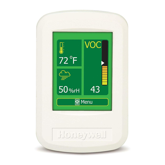
IAQPoint2 Introduction The IAQPoint2 indoor air quality monitor features a simple-to-use, customizable touchscreen display along with triple monitoring of indoor air quality parameters (carbon dioxide or volatile organic compounds, plus temperature and humidity) and facilitates demand-controlled ventilation� The IAQPoint2 monitor can increase energy efficiency in commercial buildings by triggering fan activation as a standalone solution or via a building automation system�... -
Page 6: Air Quality
IAQPoint2 Air Quality Traditional carbon dioxide sensors do not respond to changes in air quality caused by odors, cigarette smoke, and other volatile organic compounds� This graph illustrations the relationship between CO levels and concentrations of volatile organic compounds in a typical meeting room�... -
Page 7: Danger/Warning/Caution/Notes
IAQPoint2 Danger/Warning/Caution/Notes DANGER Danger messages address situations that could result in loss of life� WARNING Warning messages address situations that could result in injury or critical damage to the monitor� CAUTION Caution messages address situaltions that could result in damage to the monitor�... -
Page 8: Contact Information
CH-8610 Uster Switzerland Tel: +41 (0)1 943 4300 Fax: +41 (0)1 943 4398 gasdetection@honeywell.com Asia Pacific Honeywell Analytics Asia Pacific #508, Kolon Science Valley (1) 187-10 Guro-Dong, Guro-Gu Seoul, 152-729 Korea Tel: +82 (0)2 6909 0307 Fax: +82 (0)2 2025 0328 analytics�ap@honeywell�com... -
Page 9: Glossary
IAQPoint2 Glossary Term Description Automatic Baseline Correction American Society of Heating, Refrigeration, and Air Conditioning Engi- ASHRAE neers aldehyde a type of organic compound American Wire Gauge; smaller numbers equate to larger wire diameters BACnet Building Automation and Control Networking Protocol... -
Page 10: Configurations
IAQPoint2 Configurations The base configuration of the IAQPoint2 monitor: • CO or VOC sensor • analog output (4-20 mA or 0-10 V) • wall mount • no display Figure 4. IAQPoint2 base configuration The monitor is also available with an LCD touchscreen display with either analog output or digital output�... - Page 11 IAQPoint2 recessed calibration pushbutton and con rmation LED non-display bezel mini-USB port case hex screws (2) touchscreen display housing LCD bezel inlet vents gas calibration port Figure 6. Parts of the IAQPoint2 wall-mount monitors...
- Page 12 IAQPoint2 case hex screws (2) mounting plate touchscreen display recessed calibration pushbutton and con rmation LED sampling tube mini-USB port housing terminal inlet vents block cover non-display bezel Figure 7. Parts of the IAQPoint2 duct-mount monitors gas calibration port...
-
Page 13: Dimensions
Figure 8. Monitors’ sizes Wiring and installation IAQPoint2 models are available for wall-mounting or duct-mounting� Wall-mount units can be installed on standard single-gang junction boxes� Locate the monitor in an area easily accessible by a technician� Avoid locations in which the monitor will be subjected to vibration or rapid temperature fluctuations�... - Page 14 Figure 9. Wiring schematic Digital models of the IAQPoint2 monitor should be wired as indicated on the label� Note that the meaning of the A and B symbols for EIA/RS-485 wiring varies among vendors� Terminal 6 corresponds to BACnet ‘+’, the Modbus ‘D1’ and the EIA/RS-485 ‘B’�...
-
Page 15: Wall-Mounting Procedure
IAQPoint2 Wall-mounting procedure The monitor can be mounted onto a wall by following this procedure� Monitors with the optional temperature sensor must be mounted in a location with relatively still air� 1� Center the mounting plate over the wires from the wall with the mounting holes�... - Page 16 IAQPoint2 NOTE The image does not auto-rotate� Mount the monitor so that the image is displayed right-side up� with relay backplate back of the bezel analog configuration switches (up for 4-20 mA, down for 0-10 v) relay terminal block without relay...
- Page 17 IAQPoint2 with relay backplate bezel Network termination 120 Ω resistor switch must be off (left) unless at the end of network. relay terminal block without relay backplate bezel Network termination 120 Ω resistor switch must be off (left) unless at the end of network.
-
Page 18: Duct-Mounting Procedure
Do not mount the monitor on the top or bottom of a duct� (The sampling tube is designed for horizontal installation�) Installation kit: • IAQPoint2 monitor • backplate • Two metal screws • Quick Start Guide (one page, paper) - Page 19 IAQPoint2 connector collar gasket intake/ gasket exhaust sampling tube O-ring mounting plate clamp mounting plate connector orientations cross-sections in cross-sections in vertical ducts horizontal ducts air flow air flow air flow air flow Figure 14. Sampling tube and mounting plate 8�...
- Page 20 IAQPoint2 NOTE For accurate measurements, there must be air movement in the duct� with relay without relay Relay terminal block Analog configuration switches Analog configuration switches (to the right for 0-10 v, (to the right for 0-10 v, to the left for 4-20 mA)
- Page 21 IAQPoint2 with relay without relay Relay terminal block Load resistors are not used in Load resistors are not used in digital models. Slide all three digital models. Slide all three switches to the left to avoid switches to the left to avoid loading the RS-485 network.
-
Page 22: Operation
VOC Configurations The VOC sensor used with the IAQPoint2 monitor requires no calibration but allow it fifteen minutes to warm up each time power is applied� The sensor will use the air in which it is powered up as the baseline� The VOC sensor will adapt to the... -
Page 23: Warm-Up
The user will be presented with one of two interfaces, depending on the password that is entered� Figure 20 in the Menus section is a map of all of the IAQPoint2 monitor’s interface options� Exact options will vary depending on the configuration of the unit�... -
Page 24: Output Levels
IAQPoint2 Output levels Models without the optional temperature/humidity sensor will report gas concentrations on channel 2 identically to channel 1� Analog Channel 1 Output Relativ Output Output Output Output Tempe Tempe Conce Curren Curren Voltag Voltag Humidi rature rature ntratio... - Page 25 IAQPoint2 Analog Channel 3 Output Sensor Normal Sensor Normal Relative Humidity ( % ) Relative Humidity ( % ) Sensor Absent or In Fault Figure 19. Relative humidity current and voltage output levels...
-
Page 26: Menus
27 page 28 page 28 page 27 page 38 page 39 page 30 page 36 page 32 page 34 page 37 page 38 page 37 page 36 √ √ page 35 Figure 20. The IAQPoint2 Air Quality Monitor menu map... -
Page 27: Default Display
IAQPoint2 The contents of some menus vary depending on the configuration of the monitor and on which password was entered� Those variations are noted in the appropriate sections� Menu naming conventions Menus are navigated by pressing the appropriate buttons� Active buttons are indicated by yellow borders�... - Page 28 IAQPoint2 Navigation Most screens include three navigation buttons at the bottom of the display: Press the Accept button [ ] to accept displayed entries or values and return to the ü previous menu� Press the Delete button [ ß ] to delete values (one character at a time)�...
- Page 29 This screen shows the factory settings of the IAQPoint2 monitor (serial numbers, software version number, and time stamp)� Below the time stamp is an indication of the IAQPoint2 hardware output type� This can be either “Analog” or “RS-485” for the BACnet/Modbus version� The bottom line shows whether the optional temperature and relative humidity sensor is fitted�...
- Page 30 IAQPoint2 IAQPoint2 units without the optional temperature and humidity sensor, lines three through five contain “TRH Sensor Not Fitted�” Line six conveys the period of the occupied timer and the relay source� The occupied timer period can be set from 1 minute to 2 hours in six steps� The relay source indicates the function of the optional relay�...
- Page 31 IAQPoint2 Configure menu > Configure Setpoints > Set Gas Setpoint The setpoint for CO or VOCs is changed at this screen� This affects the position of the white triangle indicator on the main screen� This value is reported over BACnet and Modbus�...
- Page 32 IAQPoint2 than the minimum temperature setpoint� The default temperature is 86°F (30°C)� The minimum temperature setpoint is changed in the same manner� The minimum value in the range can be any temperature between 32 and 122°F (0-50°C)� It must be lower than the maximum temperature setpoint� The default setting is 50°F (10°C)�...
- Page 33 (The relay is configured via the Configure > Configure Outputs > Set Relay Source screen�) The relay flow of the IAQPoint2 air quality monitor is shown in this illustration� Gas Sensor Value...
- Page 34 IAQPoint2 Configure menu > Configure Outputs > Set Relay Source The functions of the relay are adjusted at this screen� The monitor normally responds to gas concentrations (i�e�, the air quality level)� The Set Relay Source feature allows a relay to respond to the occupied timer or, for digital versions, to the network (fieldbus, for example, in BACnet systems)�...
- Page 35 IAQPoint2 Configure menu > Display submenu > Main Display Dataset Main Display Dataset CO2 Graphics CO2 Numeric Temperature Relative Humidity Occupied Status How much information is displayed on the home screen is determined at this screen� For example, some users may choose to disable the display of some information for simplicity and less distraction�...
- Page 36 The monitor can be configured for either BACnet or Modbus from the Set Protocol screen� The default is Modbus� If the monitor is to communicate with the Honeywell Analytics 301C controller, this screen should be configured for Modbus, 9600 baud, and no parity� The address must be unique�...
- Page 37 IAQPoint2 Configure menu > Configure Passwords & Reset > Set Password 1 or 2 Configure Password Set Password 1 Set Password 2 Reset Configuration Reboot Password options are available through the Configure Passwords menu� The Password Level 1, Password Level 2, and Reset to Factory Settings options are described below�...
- Page 38 IAQPoint2 Calibrate menu Calibrate Calibrate Gas Cal Temperature Calibrate RH Calibration procedures are initiated at the Calibrate menu� Refer to local regulations for calibration requirements� Calibrate the monitor at least once a year to maintain the highest level of accuracy�...
- Page 39 IAQPoint2 Calibrate > Cal Temperature Cal Temperature Current 77.3 Target 77.3 F Calibrate Offset Revert to Factory Cal This screen is available only on models with the optional temperature humidity sensor and after the level 2 password has been entered� This feature allows the monitor to be installed in an area that is known to be characteristically cooler or warmer than the rest of the space (e�g�, near a photocopier)�...
- Page 40 IAQPoint2 Calibrate > Calibrate mA Output Cal mA Output Select Channel Select Extrema Norm The monitor’s mA output for each of three channels can be calibrated to match that of a site’s external HVAC equipment� Channel 1 measures gas levels, channel 2 can be configured to measure either a gas or temperature�...
- Page 41 IAQPoint2 Language menu Language / Langage English Français The IAQPoint2 monitor can be configured for English or French (Français)� The default language selection is English�...
-
Page 42: Calibration
If ABC is not desired, it can be disabled in the Configure > Configure Outputs > Auto Baseline menu� 4� Connect a cylinder of a test gas of known concentration (e�g� Honeywell part M-501010, 1,000 ppm CO ) to a 0�5 lpm regulator (e�g�... -
Page 43: Voc Calibration
VOC sensor be exposed to fresh air for at least an hour of each day� No manual calibration for VOCs is possible� A bump test of wall-mount models may be performed be simply breathing on IAQPoint2� Temperature Calibration The optional IAQPoint2 temperature sensor is pre-calibrated and usually does not shift with age�... -
Page 44: Rh Calibration
11� When satisfied, with the temperature reading, navigate to the main screen� rH Calibration The optional IAQPoint2 relative humidity sensor is pre-calibrated� However, exposure to certain chemicals may cause the reading to shift over time� The humidity reading may be recalibrated using the following procedure: 1�... -
Page 45: Troubleshooting
The event history of recent fault codes (approximately the last fifteen) is displayed but fault codes are not stored� A level 2 password is required for access to the event history screen� IAQPoint2 Troubleshooting Guide Affected Version... - Page 46 IAQPoint2 IAQPoint2 Troubleshooting Guide Affected Version Models Diagnostic Symptom Cause Solution Tests Confirm that switches Internal 500 Ω for volt/milliamp Slide switches to the mode are in the load resistors are correct position as desired position as improperly switched described in Figures described in Figures in circuit.
- Page 47 IAQPoint2 IAQPoint2 Troubleshooting Guide Affected Version Models Diagnostic Symptom Cause Solution Tests Ch1 analog output • • • • produces 4 mA or If fitted, VOC sensor Wait until 15 minutes 2 VDC even when is in warmup mode. after powerup.
- Page 48 IAQPoint2 IAQPoint2 Troubleshooting Guide Affected Version Models Diagnostic Symptom Cause Solution Tests Temperature reading • • • • The monitor is not Remount vertically, ac- is higher than an mounted vertically cording to installation accurate reference as required. instructions. instrument.
- Page 49 IAQPoint2 IAQPoint2 Troubleshooting Guide Affected Version Models Diagnostic Symptom Cause Solution Tests ABC feature is disabled unintention- Turn on ABC. (Allow ally, thus preventing 3 weeks for automatic automatic baseline corrections.) correction. If ABC is disabled Calibrate as described intentionally, unit is on page 40.
- Page 50 IAQPoint2 IAQPoint2 Troubleshooting Guide Affected Version Models Diagnostic Symptom Cause Solution Tests Review wiring and Network polarity is installation instruc- incorrect. tions.. Configure for Modbus Protocol is wrong. or BACnet. Configure for same Baud rate is wrong. speed as other devices Look for 'N' at top of on the network.
-
Page 51: Sensor Poisons/Inhibitors
IAQPoint2 Maintenance The built-in ABC algorithm makes maintenance unnecessary in normal environments� Cleaning Clean the case and the touchscreen by wiping gently with a soft cloth dampened only with water� Do not allow water to enter the monitor’s case� Do not spray any liquids on the touchscreen or the case�... -
Page 52: Specifications
IAQPoint2 Specifications Description Value Non-dispersive infrared (NDIR) with automatic background calibration Detection method (ABC) algorithm Monitor with Ranges 0-2,000 ppm, 0-5,000 ppm sensor 1, 2, 3 Accuracy ±30 ppm ±3% of reading at 25°C from 0 to 2,000 ppm Response Time <60 seconds... -
Page 53: Modbus Registers
IAQPoint2 Modbus registers Some models of the IAQPoint2 contain a digital interface for communicating over RS-485 networks� This interface can be switched in software to use either the Modbus RTU or BACnet MS/TP protocols� It can communicate at any speed from 4800 to 115,200 baud�... - Page 54 Reserved for future enhancements� Reserved for future enhancements� Reserved for future enhancements� Occupied Timer This bit is true if the occupied timer inside the IAQPoint2 is running� See Running Figure 22 for an illustration of this� Relay Fitted This is true if the PEM backplate contains the optional relay�...
-
Page 55: Bacnet Introduction
BACnet� Each object has several properties which can be read and sometimes written� All of the objects and properties of the IAQPoint2 BACnet device are listed in the table at the end of this section� A BACnet protocol implementation conformance statement (PICS) is included in this section, as well�... - Page 56 IAQPoint2 BACnet Protocol Implementation Conformance Statement List all BACnet Interoperability Building Blocks Supported (Annex K): BIBB Service DS-RP-B Data Sharing - ReadProperty-B DS-RPM-B Data Sharing - Read Property Multiple-B DS-WP-B Data Sharing - Write Property-B DM-DDB-B Dynamic Device Binding DM-DOB-B...
- Page 57 IAQPoint2 BACnet Protocol Implementation Conformance Statement Object Object Object Supported Dynamically Dynamically Creatable Deletable ACCUMULATOR ANALOG INPUT ANALOG_OUTPUT ANALOG_VALUE AVERAGING BINARY_INPUT BINARY_OUTPUT BINARY_VALUE CALENDAR COMMAND DEVICE EVENT_ENROLLMENT FILE GROUP LOOP LIFE_SAFETY_DEVICE LIFE_SAFETY_ZONE MULTISTATE_INPUT MULTISTATE_OUTPUT MULTISTATE_VALUE NOTIFICATION_CLASS PROGRAM PULSE CONVERTER SCHEDULE...
- Page 58 IAQPoint2 BACnet Protocol Implementation Conformance Statement Analog Input Object Optional Properties Writable Properties (Not Proprietary Property must by the Standard) Reliability Present Value None Out Of Service Object Name Engineering Units* Present Value – Range Restriction for GAS_RDG_AI (Object Identifier 0): 400 to 5000 ppm or 10 to 100% depending on sensor fitted�...
- Page 59 IAQPoint2 BACnet Protocol Implementation Conformance Statement Engineering Units – Applies to only Temperature setpoint (Object Identifier 4)� – Valid Options: Degrees C (62) or Degrees F (64)� Reliability - Always NO_FAULT_DETECTED Binary Input Object Writable Properties (Not Optional Properties Proprietary Property...
- Page 60 IAQPoint2 BACnet Protocol Implementation Conformance Statement Device Object Writable Properties (Not Optional Properties Proprietary Property must by the Standard) Location Object Identifier* None Description Location Max Master Description Max Info Frames Max Master * The uniqueness of Object Identifier shall be ensured by the writing device� The PEM will not have a mechanism to ensure the internetwork-wide uniqueness of these properties�...
- Page 61 IAQPoint2 BACnet Protocol Implementation Conformance Statement Data Link Layer Options: p BACnet IP, (Annex J) p BACnet IP, (Annex J), Foreign Device p ISO 8802-3, Ethernet (Clause 7) p ATA 878�1, 2�5 Mb� ARCNET (Clause 8) p ATA 878�1, EIA-485 ARCNET (Clause 8), baud rate(s) ____________...
-
Page 62: Bacnet Objects And Properties
Honeywell Inc� (17) not writable apdu_timeout unsigned not writable application_software_ character string not writable version description character string Honeywell Indoor Air Quality Sensor not writable firmware_revision character string not writable location character string "location" Any unique string 1-22 bytes max_apdu_length_ac- unsigned... - Page 63 IAQPoint2 BACNet Objects and Properties Property Data Type Read Value Writable Values object_identifier analog_input (0) not writable object_type enumerated analog_input (0) not writable "if gas sensor fault Fault (1), event_state enumerated not writable else normal (0)" object_name character string "GAS_RDG_AI"...
- Page 64 IAQPoint2 BACNet Objects and Properties Property Data Type Read Value Writable Values object_identifier analog_value (3) not writable object_type enumerated analog_value (2) not writable event_state enumerated normal (0) not writable object_name character string "GAS_SPT_AV" Any unique string 1-22 bytes out_of_service boolean...
- Page 65 IAQPoint2 BACNet Objects and Properties Property Data Type Read Value Writable Values object_identifier binary_input (6) not writable object_type enumerated binary_input (3) not writable event_state enumerated normal (0) not writable object_name character string "IAQGOOD_BI" Any unique string 1-22 bytes out_of_service boolean FALSE "true"...
- Page 66 IAQPoint2 BACNet Objects and Properties Property Data Type Read Value Writable Values object_identifier binary_output (8) not writable object_type enumerated binary_output (4) not writable event_state enumerated normal (0) not writable object_name character string "RLY_DRV_BO" Any unique string 1-22 bytes out_of_service boolean...
-
Page 67: Limited Warranty
60069, in a package equal to or in the original container� The Product will be returned freight prepaid and repaired or replaced if it is determined by Honeywell Analytics that the part failed due to defective materials or workmanship� The repair or replacement of any such defective part shall be Honeywell Analytics’... - Page 68 IAQPoint2...
-
Page 69: Index
IAQPoint2 Index Full Scale screen 30 glossary 7 90DM4 monitor 3 in fresh air 21 301C controller 34 sensor, calibration 40 Setpoint screen 29 commissioning 20 Configurations 8 hazardous locations 12 configuration, hysteresis 7, 27, 29 ABC, see automatic baseline base 8 Hyst�... - Page 70 IAQPoint2 software version number 27 Status screen 28 offset, humidity 37, 42 temperature 20, 37, 41 Operation 20 temperature fluctuations 11 O-ring 17 Temp Setpoint screen 29 output levels 22, 23 Temp� Units screen 33 test gas 11, 40, 49 touchscreen 3, 8, 9, 10, 21...
- Page 72 IAQPoint2 Air Quality Monitor Revision 1 July 2012 ©2012 Honeywell Analytics...
Need help?
Do you have a question about the IAQPoint2 and is the answer not in the manual?
Questions and answers