Honeywell Bendix/King KMD 850 Pilot's Manual Addendum
Digital weather radar function
Hide thumbs
Also See for Bendix/King KMD 850:
- Pilot's manual addendum (136 pages) ,
- Pilot's manual addendum (23 pages) ,
- Pilot's manual addendum (33 pages)

Related Manuals for Honeywell Bendix/King KMD 850


Summary of Contents for Honeywell Bendix/King KMD 850
- Page 1 KMD 850 Multi-Function Display Digital Weather Radar Function Pilot’s Guide Addendum For Software Version 01/13 or later 006-18235-0000 Revision 3 Jun/2004...
-
Page 2: Copyright Notice
©2000-2002, 2004 Honeywell International Inc. Reproduction of this publication or any portion thereof by any means without the express written permission of Honeywell International Inc. is prohibited. For further information contact the Manager, Technical Publications; Honeywell, One Technology Center, 23500 West 105th Street, Olathe, Kansas 66061. - Page 3 Revision History Manual KMD 550/850 Digital Weather Radar Pilot’s Guide Addendum Revision 3, June 2004 Part Number 006-18235-0000 Summary Auto Standby may now be disabled during system configuration Miscellaneous corrections...
- Page 4 Revision History Manual KMD 550/850 Digital Weather Radar Pilot’s Guide Addendum Revision 2, January 2002 Part Number 006-18235-0000 Summary Complete manual revision Miscellaneous corrections...
- Page 5 Revision History Manual KMD 550/850 Digital Weather Radar Pilot’s Guide Addendum Revision 1, April 2001 Part Number 006-18235-0000 Summary Added Stabilization function on WX Radar Page Changed format of TILT field Radar faults now supported Added Auto Tilt Added Manual Gain Added Sector Scan Added Automatic Range Limiting Added 5 nm and 320 nm range settings...
- Page 6 Revision History Manual KMD 550/850 Digital Weather Radar Pilot’s Guide Addendum Revision 0, October 2000 Part Number 006-18235-0000 Summary This is the original release of this publication.
-
Page 7: Table Of Contents
Table of Contents INTRODUCTION ..........1 NORMAL OPERATION . - Page 8 Table of Contents Intentionally left blank Rev 2 Jan/2002 KMD 850 Wx Radar Addendum...
-
Page 9: Introduction
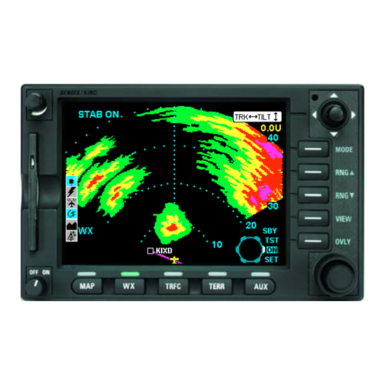
Note: The KMD 850 can interface with many different types of radar and the screen displays may vary compared to the examples shown in this manual. The Bendix/King KMD 850 is shown below with the Weather Radar Page selected. Rev 2 Jan/2002... -
Page 10: Normal Operation
NORMAL OPERATION To display the WX Radar page press the WX button. Note that in some installations this button may have to be pushed multiple times to switch between radar and stormscope. The following illustration defines the data that appears on the WX Radar Page when the radar is active and the horizontal view is displayed: 1 Aircraft Symbol 2 Knob Function Label - Rotating the outer knob selects between... -
Page 11: Operational Controls Summary
OPERATIONAL CONTROLS SUMMARY MODE - Toggles between WX, WX/ARL (Auto Range Limiting) and MAP (ground mapping) modes. NOTE: Not all weather radar systems support Auto Range Limiting. RNG - Range keys clear the display and either increase or decrease the displayed range. VIEW - Toggles between Horizontal and Vertical Profile views. -
Page 12: Weather Radar Overview
WEATHER RADAR OVERVIEW The radar display has been calibrated to show five levels of target inten- sity: Black (level 0), Green (level 1), Yellow (level 2), Red (level 3), and Magenta (level 4). The meaning of these levels is shown in the following chart as to their approximate relationship to the Video Integration Processor (VIP) intensity levels used by the National Weather Service. -
Page 13: Power On
POWER ON When the KMD 850 is initially turned on and the WX key is pressed to select the WX Radar page the following screen will be displayed: This indicates that the weather radar sensor has been energized, is in standby mode, and is communicating properly with the KMD 850 MFD. -
Page 14: Test Mode
TEST MODE Rotating the outer knob one click clockwise will put the radar in test mode which should display a test pattern similar to the following: The display should show 4 bands of color with a green band from 10 to 20 miles, a yellow band from 20 to 30 miles, a red band from 30 to 40 miles, and a magenta band from 40 to 50 miles. -
Page 15: On Mode
ON MODE Rotating the outer knob one more click clockwise to the ON position causes the radar to begin actively transmitting and scanning. The radar icon on the icon bar now indicates energy being transmitted by the radar dish. NOTE: Whenever the weather radar icon is shown as then the radar is transmitting and appropriate precautions should be taken. -
Page 16: Vertical Profile
VERTICAL PROFILE If the radar has vertical profile capability then the track line is also used to select the area of the storm to observe vertically. Once the track line is in the proper location then pushing the VIEW key will switch to vertical profile view as shown. -
Page 17: Ground Mapping (Map) Mode
GROUND MAPPING (MAP) MODE The radar can be put into Ground Mapping mode by pressing the MODE key. Ground Mapping Mode is indicated by the word MAP in the lower left corner of the display. In Ground Mapping mode the inner knob controls the radar gain. The present setting is indicated by the white arc on the knob icon. -
Page 18: Set Mode
SET MODE When the Outer Control Knob is placed in the SET position, a display similar to Figure 1 will be displayed. These Soft Keys allow access to the functions shown. Not all these func- tions will be available in all weather radar installations. -
Page 19: Manual Gain
Auto Tilt Mode Allows the antenna position to be automatically adjusted by radar system to maintain a common beam intercept point with the earth e.g. if the last 10% of the display is ground returns, then during ascent or decent the antenna tilt is automatically changed to maintain ground returns on 10% of the display. -
Page 20: Error And Fault Messages
ERROR AND FAULT MESSAGES If the KMD 850 is not receiving any data from the weather radar sensor, the following message will be displayed and the radar icon will be shown with a red circle and slash through it. This may indicate that the radar is not receiving primary power (e.g. - Page 21 Honeywell International Inc. One Technology Center 23500 West 105th Street Olathe, KS 66061 Telephone (913) 782-0400 FAX 913-712-1302 ©2000 - 2002, 2004 Honeywell International Inc. All rights reserved. 006-18235-0000 Printed in U.S.A. Revision 3 Jun/2004...
Need help?
Do you have a question about the Bendix/King KMD 850 and is the answer not in the manual?
Questions and answers