
Related Manuals for Hand Held Products Scanteam 2070


Summary of Contents for Hand Held Products Scanteam 2070
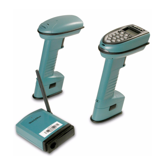
- Page 1 Cordless Scanning System SCANTEAM® 2070 Base IMAGETEAM™ 3870/75 Linear Imager SCANTEAM® 5770 Laser ™...
- Page 2 Disclaimer Hand Held Products, Inc. d/b/a HHP (“HHP”) reserves the right to make changes in specifications and other information contained in this document without prior notice, and the reader should in all cases consult HHP to determine whether any such changes have been made. The information in this publication does not represent a commitment on the part of HHP.
-
Page 3: Statement Of Agency Compliance
• Consult the dealer or an experienced radio or television technician for help. Caution: Any changes or modifications made to this device that are not expressly approved by Hand Held Products, Inc. may void the user’s authority to operate the equipment. Note: To maintain compliance with FCC Rules and Regulations, cables connected to this device must be shielded cables, in which the cable shield wire(s) have been grounded (tied) to the connector shell. - Page 4 9.0 mW at 670 nanometers per EN 60825-1:1994, Issue 2, June 1997. R&TTE Directive The IMAGETEAM 3870, SCANTEAM 5770, and SCANTEAM 2070 are in conformity with all essential requirements of the R&TTE Directive (1999/5/EC). This equipment has been assessed to the following standards: ETS 300 328 ETS 300 826 (November, 1997);...
- Page 5 SELV (Safety Extra Low Voltage) output. Patents The SCANTEAM 2070, SCANTEAM 5770, IMAGETEAM 3870, and IMAGETEAM 3875 are covered by one or more of the following U.S. patents: 3,991,299; 4,470,057, 5,021,642; 5,038,024; 5,081,343; 5,095,197; 5,144,119;...
- Page 6 Enlarged Views of Regulatory Labels - IT3870 Manufactured MAY 2000 Model # IMAGETEAM 3870 3870XX-XX Item # 12345 S / N SW 1.6/1.08 Welch Allyn, Skaneateles Falls New York 13153-0187, USA See User Guide for Patent Information Made in USA IT3870 Scanner Left Side View IT3870 Scanner...
- Page 7 Enlarged Views of Regulatory Labels - IT3875 Manufactured AUGUST 2001 Model # IMAGETEAM 3875 3875XX-XX Item # 12345 S / N SW 1.6/1.08 Welch Allyn, Skaneateles Falls New York 13153-0187, USA See User Guide for Patent Information Made in USA IT3875 Scanner Left Side View IT3875 Scanner...
- Page 8 Enlarged Views of Regulatory Labels - ST5770 Manufactured MAY 2000 Model # IMAGETEAM 3870 3870XX-XX Item # 12345 S / N SW 1.6/1.08 Welch Allyn, Skaneateles Falls New York 13153-0187, USA See User Guide for Patent Information Made in USA ST5770 Scanner Left Side View ST5770...
- Page 9 Canada ICES-003 See Manual (Reféréz-vous à la documentation) CISPR 22 CLASS B Contains TX FCC ID: EHAUL ISC: RSS/CNR 210 CANADA: 31101021090A MANUFACTURED: August 2001 MODEL # SCANTEAM 2070 S/N#: U-35-00134 ITEM #: 2070-1A REV: 3.80/1.08...
-
Page 11: Table Of Contents
Table of Contents Chapter 1 - Introduction and Installation Introduction................1-1 Cordless System: Main Components........1-3 About the Charge Pack ............1-4 Charging Your Charge Pack .......... 1-5 Discharging the Charge Pack ......... 1-6 Setting Up and Connecting the Cordless System ....1-8 Keyboard Wedge Interface .......... - Page 12 Terminal Interface Selections ..........2-6 Supported Terminals............2-6 Keyboard and Delays Selections........... 2-8 Keyboard Country ............2-8 Keyboard Style Selections..........2-9 Keyboard Style Modifiers ..........2-10 Output Delays Selection ..........2-11 Wand Emulation Selections ..........2-12 Transmission Rate Selection ........2-12 Output Polarity Selection..........
- Page 13 Host Commands (IT3875XXX-X2-1 and ST2070-5 only).3-15 Data Character Selection ..........3-17 Aux Prefix/Suffix Selections..........3-18 Decimal to Hex to ASCII Conversion Chart ....3-20 Aux Prefix Selection .............3-21 Aux Suffix Selection.............3-21 Exit Selection for Aux Prefix / Suffix ......3-21 Aux Prefix On/Off ............3-22 Aux Suffix On/Off ............3-22 Aux Port I.D.
- Page 14 System Info ................. 4-11 Chapter 5 - Application Work Group Menu Introduction ................5-1 Application Work Group Selection........5-3 ST2070-5 ................ 5-4 Remove Scanner Selection ..........5-4 Programming Keypad Macro Strings (IT3875 and ST2070-5 only)..............5-5 Initiate Key Macro (IT3875 and ST2070-5 only) ..5-6 IT3875 Font Characters Chart..........
- Page 15 Chapter 6 - Symbology Menu Introduction ................6-1 Codabar .................6-2 Start/Stop Characters ............6-2 Codabar Message Length..........6-3 Codabar Check Character ..........6-4 Concatenation ..............6-4 Code 39..................6-6 Start/Stop Characters ............6-6 Code 39 Message Length..........6-7 Check Character..............6-8 Full ASCII...............6-9 Code 39 Append ............6-10 Code 93................6-11 Code 93 Message Length..........6-12 Interleaved 2 of 5..............6-13 Interleaved 2 of 5 Message Length.......6-14...
- Page 16 PDF417 (IT3870PDF/IT3875PDF only) ......6-31 PDF417 Message Length..........6-32 Show GLI Blocks ............6-33 Macro PDF417 ............. 6-34 Show Macro Control Blocks ........6-34 Scan Diagnostics............6-35 PDF417 Learn Mode ............ 6-35 MicroPDF417 (IT3870PDF/IT3875PDF only)....6-36 MicroPDF417 Message Length........6-37 EAN•UCC Composite Symbology (IT3870PDF/IT3875PDF only) ........
- Page 17 Chapter 8 - Supported Interface Keys Keyboard Function Relationships .........8-1 Supported Interface Keys ............8-3 Chapter 9 - Product Specifications SCANTEAM 2070 Cordless Base Product Specifications ...9-1 Radio Specifications..............9-2 IMAGETEAM 3870 Cordless Linear Imager Scanner Product Specifications ............9-3 IMAGETEAM 3875 Cordless Linear Imager Scanner Product Specifications..............9-4...
- Page 18 Chapter 10 - Maintenance and Troubleshooting Maintenance ................ 10-1 Cleaning the Scan Window of the Cordless Scanner ... 10-1 Examining the Cordless Scanner and Cordless Base Housings .............. 10-1 Care and Handling of the Charge Pack ......10-2 Replacing the Interface Cable........10-2 Recharging and Replacing the Cordless Scanner’s Charge Pack..............
- Page 19 Chapter 12 - Default Chart Country Code Selections ..........12-1 Keyboard & Delays Selection........12-1 Wand Emulation Selections..........12-1 Power Settings ..............12-1 Host Port Communications ...........12-1 Auxiliary Port Communications ........12-2 Output Selections (User Feedback) ......12-3 Prefix/Suffix Selections ..........12-3 Data Formatter Selections..........12-3 Codabar Selections ............12-3 Code 39 Selection ............12-4 Code 93 Selection ............12-4 Interleaved 2 of 5 Selection ..........12-4...
-
Page 21: Chapter 1 - Introduction And Installation
Introduction and Installation Introduction The cordless scanning system consists of the SCANTEAM 2070 Base unit and at least one IMAGETEAM 3870 Cordless Linear Imager, IMAGETEAM 3875 Cordless Linear Imager, or SCANTEAM 5770 Cordless Laser Scanner. Up to nine IT3870/IT3875 or ST5770 scanners may be associated with one base. - Page 22 The cordless system can be programmed for many communications parameters and input/output protocols compatible to the host, as well as advanced data editing and formatting. Programming is accomplished by using the single programming bar codes in this manual. This section contains the following information: •...
-
Page 23: Cordless System: Main Components
Cordless System: Main Components Indicator LED Cordless Scanner Left Side View Scan (with charge pack) Window Trigger Charge Pack Clip (2 places) Charge Pack Antenna Cordless Base Back View External Power Connector Keyboard/Terminal and RS-232 Connector (Host Port) Aux RS-232, Service Port, and Wand Emulation Output Connector 1 - 3... -
Page 24: About The Charge Pack
About the Charge Pack (CLESS/NIMH/S) Power is supplied to the cordless scanner by a rechargeable charge pack that snaps onto the bottom of the scanner. Each scanner is shipped with a charge pack. (See “Charge Pack Specifications (CLESS/NIMH/S)” on page 9-6 for technical specifications.) Note: Order backup charge pack(s) or replacements from your distributor. -
Page 25: Charging Your Charge Pack
Proper Disposal of the Charge Pack When the charge pack has reached the end of its useful life, the charge packs should be disposed of by a qualified recycler or hazardous materials handler. Do not incinerate the charge pack or dispose of the charge pack with general waste materials. -
Page 26: Discharging The Charge Pack
When the charge pack needs recharging, the yellow LED on top of the scanner pulses in short, continuous blinks when the trigger is pulled. If the LED stops flashing when the temperature lowers or you do not use the charge pack for some time, you still need to charge the charge pack. - Page 27 IMAGETEAM 3875 You may automatically discharge the IT3875 charge pack by scanning the following bar code. The scanner remains operational during the discharge; however the status LED flashes like a “heartbeat.” IT3875 Charge Pack Discharge 1 - 7...
-
Page 28: Setting Up And Connecting The Cordless System
Setting Up and Connecting the Cordless System Install the base and cordless scanner by following the steps shown below: Important: Make sure the cordless scanner’s charge pack has been fully charged. See “Charging Your Charge Pack” on page 1-5 for charging instructions. -
Page 29: Rs-232 Interface
RS-232 Interface In an RS-232 configuration, connect your interface cable between the base unit and the host system (steps 1-3, shown in the illustration below). You also need to use an external power supply. Contact your distributor for more information on ordering power supplies or RS-232 cables. - Page 30 4. Using the cordless scanner, scan the Association Bar Code (the bar code label on the top of the base) to link that scanner to the base. Linear Imager or Laser Scanner Association Bar Code Cordless Base Two quick beeps followed by clicking, then a single beep indicates a “good” association.
-
Page 31: Connecting More Scanners To The System
Connecting More Scanners to the System Up to nine cordless scanners may be associated with one base unit. Add more cordless scanners to a base unit by following the steps shown below: 1. Make sure the cordless scanner’s charge pack has been fully charged. 2. -
Page 32: Beeper And Led Sequences And Meaning - It3870/It3875
Beeper and LED Sequences and Meaning - IT3870/ IT3875 The base contains a green LED that indicates the status of the unit and verifies its communication with the host system. The IT3870/IT3875 contains an LED on the top of the unit to indicate its power up, communication, and charge pack status. -
Page 33: Beeper And Led Sequences And Meaning - St5770
Beeper and LED Sequences and Meaning - ST5770 The ST5770 contains a beeper and two LEDs on the top of the unit (green and yellow) to indicate its power up, communication, and charge pack status. The tables below list the indication and meaning of the beeps and LED illumination scanner. -
Page 34: Led Sequences And Meaning - St2070
LED Sequences and Meaning - ST2070 The base contains a green LED that indicates the status of the unit and verifies its communication with the host system. ST2070 Base LED Indication Sequence Meaning LED on continuously Power on, system idle LED blinks, long duration Power on, diagnostic error LED blinks, short duration... - Page 35 RF (Radio Frequency) Module Operation The cordless system uses a state-of-the-art two-way 2.4 GHz frequency-hopping spread spectrum radio to transmit and receive data between the scanner and the base. Designed for point-to-point and multipoint-to-single point applications, the radio transmits data at a rate of 1 megabit per second (Mbps). The radio operates using a license free ISM band, which sends relatively small data packets at a fast data rate over a radio signal with randomly changing frequencies, makes the cordless system highly responsive to a wide variety of...
-
Page 36: System Conditions
Cordless Scanner Scanner Assembly Decode/Control Assembly Trigger Engine Handle (Handle Board) Assembly Housing Scan Engine Engine Port (Linear Imag- Control Menu I/O HHLC I/O er or Laser Trig/Decode Power Mgmt Beeper Beeper Port Antenna RF Port Module Download Port Engine Hsg Window/Lt Pipe Charge Port Charge Pack... - Page 37 Scanner is Out of Range The cordless scanner is always in communication with its base, even when it is not transmitting bar code data. Whenever the scanner can’t communicate with the base for a three second interval, it is out of range. If the trigger is pulled while the scanner is out of range, the red LED illuminates on the IT3870/IT3875 and the green and yellow LEDs illuminate on the ST5770.
-
Page 38: Communication Between The Cordless System And The Host
Swapping Scanners Between Two Systems with Nine Scanners on Each You may use the Remove Scanner Selection (page 5-4) to disassociate any scanner. Add a new scanner by scanning the association label with the new scanner. If you cannot scan the disassociation label because the scanner you are trying to disassociate was damaged, remove power from that scanner and it automatically disassociates in approximately three seconds. - Page 39 When data is scanned, the data is sent to the host system via the base unit. Confirmation from the host system or the base indicates that the data sent was received by the host. The cordless scanner recognizes two forms of host confirmation: data acknowledgement (ACK) from the base unit or an “ACK”...
-
Page 40: Auxiliary Port
Acknowledgement from the Host Host system confirmation may be implemented with a bi-directional interface like RS-232. In this configuration, when the base unit receives the scanned data from the scanner and forwards it to the host, the cordless system waits for a signal from the host that it received the data. - Page 41 Aux Port as an RS-232 Input Port When the auxiliary port is configured as an input port, incoming messages can be passed on to the host system “as is” or they can be manipulated by the base prior to sending to the host system. This manipulation may include attaching prefixes/suffixes to the message and/or data formatting the message.
-
Page 42: Accessories For The Cordless System
Accessories for the Cordless System Several accessories are available for the cordless system. Contact your distributor for more information or to order accessories. Charge Packs (CLESS/NIMH/S) The charge pack for the cordless scanner is a rechargeable Nickel Metal Hydride (NiMH) pack. The unique design of the charge pack it to be directly charged in a two-prong wall outlet commonly used in North America. - Page 43 Wall Mount Kit (Industrial) Similar to the standard wall mount holder, the rubberized fingers on the industrial wall mount holder are smaller to maintain a firm grasp on the scanner under jolting and jarring conditions, such as those expected in fork lift applications. Head Cover The head cover features a “D”...
- Page 44 1 - 24...
-
Page 45: Chapter 2 - Quick Start & Interface Menu
Quick Start & Interface Menu Introduction Use this section to program the cordless system to work with your terminal or computer (host system). This programming section contains the following menu selections: • Plug and Play • Terminal Interface • Country Code •... -
Page 46: Plug And Play Selections
Plug and Play Selections Note: Plug and Play menu codes will default all settings before programming the interface. Industrial Interface: IBM PC <Factory Default> IBM PC AT and Compatibles Interface (also PS/2 30-286, 50, 55SX, 60, 70, 70-061, 70- 121, 80) Note: The bar code above also programs a CR (carriage return) suffix. -
Page 47: Ibm 468X/9X Ports 5B, 9B, And 17 Interface
IBM 468X/9X Ports 5B, 9B, and 17 Interface Scan one of the following “Plug and Play” codes to program the interface for IBM 4683 Port 5B, 9B, or 17. Note: When using any of the IBM 4683 interfaces, the maximum allowable data rate into the base aux port is 9600 baud. -
Page 48: Industrial Interface, Aux Port: Wand Emulation Black High
Industrial Interface, Aux Port: Wand Emulation Black High Wand Emulation (Code 39 Format) Interface Wand Emulation (Same Code Format) Interface Supports Code 39, UPC, EAN, Code 128, Interleaved 2 of 5, and Codabar. All other codes are output as Code 39. Note: The two bar codes above also program the following parameters: Programmable Option Setting Transmission Rate... -
Page 49: Non Decoded Laser Emulation (Hhlc)
Non Decoded Laser Emulation (HHLC) Use HHLC when connecting to a secondary terminal with integral decoding. This setting also sets the transmission rate to 37 scans per second and polarity to white high. Non Decoded Laser Emulation 2 - 5... -
Page 50: Terminal Interface Selections
Terminal Interface Selections If your terminal is not one of the Plug and Play options, you must program your terminal’s interface using one of the “Terminal I.D.” numbers listed below. To program your terminal to the scanner, scan the Program Terminal Interface bar code below, then scan the appropriate Terminal I.D. - Page 51 Supported Terminals (Continued) Terminal Terminal Model(s) I.D. IBM 122 Key 3179-1, 3191, 3192, 3471, 3472, 3194 IBM 122 Key 3196, 3197, 3476, 3477, 3482, 3486, 3487, 3488 276, 277, 486, 487, 587, 12471-01 IDEAssociates Lee Data Link ANSII MC-3+, MC-5 Link ASCII MC-3+, MC-5 Link Enhanced PC...
-
Page 52: Keyboard And Delays Selections
Keyboard and Delays Selections Keyboard Country This allows you to re-map the keyboard layout for your selected country. As a general rule, the following characters are not supported by the cordless system for countries other than the United States: @ | $ # { } [ ] = / ‘ \ < > ~ *United States Belgium Denmark, Finland,... -
Page 53: Keyboard Style Selections
Keyboard Style Selections Using the Keyboard Style selections, you can program special keyboard features, such as Caps Lock and Shift Lock. Regular is used when you normally have the Caps Lock key off. Caps Lock is used when you normally have the Caps Lock key on. Shift Lock is used when you normally have the Shift Lock key on (not common to U.S. -
Page 54: Keyboard Style Modifiers
Keyboard Style Modifiers This allows you to program special keyboard features, such as CTRL+ codes and Turbo Mode. Control + ASCII Mode On: If you scan this selection, the cordless system sends key combinations for ASCII control characters for values 00-1F. Refer to page 8-1 for CTRL+ Values. -
Page 55: Output Delays Selection
Automatic Direct Connect: When Emulate External Keyboard has been selected (page 2-9), Automatic Direct Connect Mode keeps the integrated keyboard from becoming permanently disabled. (This selection disables the keyboard for the duration of the bar code transmission.) Automatic Direct Connect Mode On *Automatic Direct Connect Mode Off Output Delays Selection This selection provides control of the time delays between data output by the... -
Page 56: Wand Emulation Selections
Wand Emulation Selections Note: When in Wand Emulation mode, bar code data containing more than 48 characters may not be sent to the host device. Transmission Rate Selection This programming selection sets the transmission rate from 10 ips (inches per second) to 300 ips if the cordless system is in Wand Emulation mode. -
Page 57: Output Polarity Selection
Output Polarity Selection This selection allows you to set the output logic convention for the digital output. The choices are White High and Black High. White High *Black High 2 - 13... -
Page 58: Power Settings
Power Settings Base Low Power Mode You may want the base unit to draw less power when it is being powered by a portable data terminal or laptop. Use Base Low Power mode to tell the base to draw less power. *Off Note: Using Base Low Power Mode increases latency in radio communications. -
Page 59: Charge Pack Conservation Mode
Charge Pack Conservation Mode The scanner offers three low power modes: 1) No timeout, 2) Don’t check base network before timeout, and 3) Check base network before timeout. The lowest standby current is achieved with “No timeout” selected. Radio contact is maintained and workgroup configuration settings are maintained. “No timeout”... -
Page 60: Timeout Period Selections
Timeout Period Selections Timeout after 15 minutes Timeout after 30 minutes Timeout after 45 minutes *Timeout after 1 hour Low Power Timeout (IT3875 only) The IMAGETEAM 3875 enters a sleep mode when low power timeout occurs. When the scanner goes to sleep, the keypad is temporarily disabled. To wake the scanner from the sleep mode pull the trigger or press ENTER. -
Page 61: Factory Default And Revision Report Selections
Factory Default and Revision Report Selections Reset Factory Settings Scanning the Factory Default Settings bar code resets the cordless system to the original factory settings, clearing any programming changes you may have made. You may reset the factory default settings for the current application group or for all application groups. - Page 62 2 - 18...
-
Page 63: Chapter 3 - Communications Menu
Communications Menu Introduction Use this section to program the communications parameters for the cordless system. This programming section contains the following menu selections: • Host Port Protocol/Communications (RS-232) • Auxiliary Port Protocol/Communications (RS-232) 3 - 1... -
Page 64: Default Host Port Protocol
Host Port Protocol Default Host Port Protocol <Default All Host Port RS-232 Protocol> Baud Rate Selection This selection sets the baud rate from 300 bits per second to 38,400 bits per second. Programming baud rate causes the data to be sent at the specified rate. The host terminal must be set up for the same baud rate as the cordless system to ensure reliable communication. -
Page 65: Parity Selection
Host Port Protocol Parity Selection This selection provides a means of checking character bit patterns for validity. The cordless system can be configured to operate under Even, Odd, Mark,None, or Space parity options. The host terminal must be set up for the same parity as the cordless system to ensure reliable communication. -
Page 66: Word Length Stop Bits Selection
Host Port Protocol Word Length Stop Bits Selection This selection sets the Word length at one or two stop bits. *1 Stop Bit 2 Stop Bits Hardware Flow Control Selection This selection turns on hardware flow control that checks for a CTS signal before sending data. -
Page 67: Serial Wedge Output Selection
Host Port Communications Serial Wedge Output Selection This selection selects the serial output direction required by your application. P1 and P2 are serial wedge designations printed on the serial wedge cable. Usually, one goes to the host and one goes to the terminal, depending on your specific application and the serial wedge cable. -
Page 68: Host Ack Selection
Host Port Communications Host ACK Selection Some applications require that the host terminal (or server) approve or reject incoming bar code data and notify the operator of these actions. These applications require that the host maintain control over the response indicators emitted from the source scanner. -
Page 69: Host Ack Enable
Host Port Communications Time out is indicated by three rapid beeps at the same pitch. A time out occurs if the source scanner does not receive a valid escape command in 10 seconds. If a time out occurs, the operator should check the host system to understand why a response to the scanner was not received. - Page 70 Host Port Communications Escape Commands The tables below list the escape commands that must be generated from the host system and the resulting action(s). ST5770 Escape Commands Command Action <ESC> a Beep (two high tones), illuminate green LED for two seconds <ESC>...
- Page 71 Host Port Communications IT3870/IT3875 Escape Commands Command Action <ESC> a Indicate as if successful menu change made <ESC> b Indicate as if unsuccessful menu change made Illuminate green LED for 135 milliseconds (followed by at least 70 mSecs. <ESC> 1 dark time when multiple blinks) Illuminate green LED for two seconds (followed by at least 500 mSecs.
- Page 72 Host Port Communications Decode Beep Selection Note: Decode Beep mode is active only when the programming selections Host ACK (page 3-6) or Data Format Required (page 5-26) are turned on. When Host ACK Selection is on, the scanner will only beep/blink in response to the Escape commands generated by the host.
-
Page 73: Default Auxiliary Port Protocol
Auxiliary Port Protocol Default Auxiliary Port Protocol <Default All Auxiliary Port Protocol> Baud Rate Selection This selection sets the baud rate from 300 bits per second to 38,400 bits per second. Programming baud rate causes the data to be sent at the specified rate. The device connected to the Auxiliary Port must be set up for the same baud rate as the Aux Port to ensure reliable communication. -
Page 74: Parity Selection
Auxiliary Port Protocol Parity Selection This selection provides a means of checking character bit patterns for validity. The Auxiliary Port can be configured to operate under Even, Odd, Mark, None, or Space parity options. The device connected to the Auxiliary Port must be set up for the same parity as the Aux Port to ensure reliable communication. -
Page 75: Word Length Stop Bits Selection
Auxiliary Port Protocol Word Length Stop Bits Selection This selection sets the Word Length at one or two stop bits. *1 Stop Bits 2 Stop Bits Hardware Flow Control Selection This selection turns on hardware flow control that checks for a CTS signal before sending data. -
Page 76: Ibm 4683 Async Address Selections
Auxiliary Port Communications IBM 4683 Async Address Selections If you are going to program the interface for IBM 4683 Async Addresses, you must first program the Terminal ID as 51 (see page 2-6). Then, scan one of the programming codes below for your 4683 Async Address selection. Note: When using any of the IBM 4683 interfaces, the maximum allowable data rate into the base aux port is 9600 baud. -
Page 77: Host Commands (It3875Xxx-X2-1 And St2070-5 Only).3-15
Auxiliary Port Communications Host Commands (IT3875XXX-X2-1 and ST2070-5 only) Most VersaCode script commands can be sent by RS-232 from the host to a scanner via the base unit. When the host sends the VersaCode commands, they are called Host Commands. Host Commands can be used to control every function of the scanner. -
Page 78: Protocol Selection
Auxiliary Port Input Communications Protocol Selection This selection programs the Auxiliary Port for the protocol required by the input device to the Auxiliary Port. The protocol is a set of rules concerning the exchange of data between serially communicating devices. The Auxiliary Port supports Record, Burst, and ACK/NAK protocols when receiving data from an RS-232 device. -
Page 79: Data Character Selection
Auxiliary Port Input Communications Data Character Selection This selection selects the serial output data characters that may be sent from the RS-232 device connected to the Auxiliary Port. When the Aux Port is used as an input, it is recommended (although not required) that incoming messages be “framed”... -
Page 80: Aux Prefix/Suffix Selections
Auxiliary Port Input Communications Aux Prefix/Suffix Selections Aux Prefix and Suffix Aux Prefix and Suffix characters are data characters you may assign to incoming Auxiliary Port data. Prefix Message Suffix Data frame Characters for the Prefix and Suffix are selected by their hexadecimal ASCII value, up to 12 characters each. - Page 81 Auxiliary Port Input Communications Aux Prefix and Suffix Examples Example 1: Add a Prefix To add an HT (tab) Prefix to incoming data: Step 1. Scan the Add Aux Prefix Prefix Selection bar code. Step 2. Scan 7 and 2 on the Programming Chart (inside back cover). Step 3.
-
Page 82: Decimal To Hex To Ascii Conversion Chart
Auxiliary Port Input Communications Decimal to Hex to ASCII Conversion Chart Dec. ASCII Dec. ASCII Dec. ASCII Dec. ASCII ‘ “ & ‘ < > 3 - 20... -
Page 83: Aux Prefix Selection
Auxiliary Port Input Communications Aux Prefix Selection Add Aux Prefix Default Aux Prefix (none) Clear All Aux Prefixes Aux Suffix Selection Add Aux Suffix Default Aux Suffix (CR) Clear All Aux Suffixes 1. Scan 7 and 2 and then one or more two-digit numbers and Save after scanning this pro- gramming bar code. -
Page 84: Aux Prefix On/Off
Auxiliary Port Input Communications Aux Prefix On/Off The following selections allow you to turn on and off the Aux Prefix and Suffix formatting. These codes are used when you want to toggle between turning on and off the prefix and/or suffix formatting. Aux Suffix On/Off Aux Port I.D. - Page 85 Auxiliary Port Input Communications Aux Data Format Editor Selections The Aux Data Format Editor selections are used to edit incoming data to the aux port. For example, you can use the Aux Data Format Editor to insert characters at certain points in bar code data as it is scanned. It is not necessary to use the Aux Data Format Editor.
- Page 86 Auxiliary Port Input Communications Step 6. Editor Commands Refer to the Format Editor Commands (page 3-25). Scan the symbols that represent the command you want to enter. 94 alphanumeric characters may be entered for each symbology data format. Step 7. Scan Save to save your entries. Other Programming Selections •...
-
Page 87: Send Commands
Auxiliary Port Input Communications The Aux Data Editor Commands are: • Scan F 4 (see page 3-25 for a description). • Scan 3 0 (hex value for 0). • Scan 0 3 (indicating the 0 should be sent 3 times). •... -
Page 88: Miscellaneous Commands
Auxiliary Port Input Communications F9 Search back for “xx” character from current cursor position, leaving cursor pointing to “xx” character. Syntax = F9xx (xx stands for the hex value for an ASCII code, see Hex to ASCII Conversion chart, page 3-20.) E6 Search ahead for the first non “xx”... -
Page 89: Aux Data Format Editor
Auxiliary Port Input Communications Aux Data Format Editor See through page 3-23 through page 3-26 for a description of Aux Data Format selections and commands. Enter Aux Format Default Aux Data Format Clear One Aux Data Format Clear All Aux Data Formats Save Current Changes Discard Current Changes 3 - 27... -
Page 90: Aux Data Formatter
Aux Data Formatter When Aux Data Formatter is turned off, the data coming into the aux port is output to the host as received (including prefixes and suffixes). When Aux Data Formatter is required, all incoming data must conform to an edited format or the base does not transmit the input data to the host device. -
Page 91: Chapter 4 - Imageteam 3875 Features
IMAGETEAM 3875 Features Introduction This section describes the features of the IMAGETEAM 3875’s display and keypad. Factory scripts and built-in functions are also included in this section. IT3875 Keypad The IT3875 keypad, as shown below, includes the following features: • Numeric with shifted alpha keys •... -
Page 92: Enter/Backspace
When the key is depressed and the trigger goes from released state to the pulled state, the character advances to the next selection, and you receive audible feedback. For example, if you needed to key in the following data identifier for a bar code message or a part number: 1Z12345. -
Page 93: Display
Horizontal Character Scrolling You can use horizontal scrolling for messages that are too wide to fit on the display if the current script enables it. If the selected line is too wide to fit on the display, an arrow appears at either the left or right edge of the display indicating additional characters. - Page 94 Backlight Control A backlight is provided for viewing the display in darkened area. Backlight control is a scanner independent control, not part of the work group settings. To access the backlight control, press and release the FN key, then the BACK (BK) key.
-
Page 95: System Setup
System Setup The IT3875 System Setup is a text menu for accessing the script control, work group selection, scanner ID facilities, and IT3875 information. Access the System Setup by pressing and holding the following keys together for three seconds: FN, BK, and ENTER keys, in that order. You may select an option by either pressing the number of the option or by pressing the arrow keys to highlight the selection and then pressing the ENTER key. -
Page 96: It3875Xxx-X2-0 Script Setup
IT3875XXX-X2-0 Script Setup An asterisk in the first character position indicates the active script. The scanner emits a successful menu change beep when a script is selected and exits the System Setup. Selecting 5. BACK returns to the System Setup. The Script Menu is illustrated below. -
Page 97: Run Part Number And Quantity Factory Script
Once a line is selected, it is highlighted. A highlighted line can be horizontally scrolled if there is data beyond the screen width. If the selected line is too wide to fit on the display, an arrow appears at either the left or right edge of the display indicating additional characters. -
Page 98: Product Demo Script
Instead of selecting the Run Part Number and Quantity script from the display, you may scan the following bar code. Run Part Number and Quantity Script Product Demo Script This script runs a demo that describes the top selling features of the IT3875. You may press the ENTER key to step through the demonstration. - Page 99 Run Custom Script (IT3875XXX-X2-1 and ST2070-5 only) This selection instructs the scanner to run the custom script that is designated for the current work group. The script must first be loaded into the ST2070-5 using IQ App Loader or IQ App Designer. The IT3875XXX-X2-1 supports VersaCode, a new scripting language, that is designed for data capture applications.
-
Page 100: No Script
No Script (IT3870 Emulation) This function stops the current script, disables the LCD screen, and disables keypad entry. Normal scanning and LED and beeper functions still work. Instead of selecting the No Script script from the display, you may scan the following bar code. -
Page 101: Scanner Id
Scanner ID The scanner ships with a factory default scanner ID that you may change to any four-character string. If you press or select option 1, Default ID, the factory default scanner ID displays. To modify the current Scanner ID, press or select option 2, enter a 4-character ID, then press ENTER. - Page 102 4 - 12...
-
Page 103: Chapter 5 - Application Work Group Menu
Application Work Group Menu Introduction Use this section to program parameters for application work groups for the cordless system. A work group is a collection of programming settings and a custom script that defines the personality of the scanner. A different custom script may be loaded for each work group. - Page 104 To add a new cordless scanner to an established group, associate the scanner to the base and scan the application work group number. The scanner will automatically reconfigure to operate and send data to the host system according to that group’s programmed selections. Any programming selections you change or make with one cordless scanner will affect all the scanners in the same work group.
-
Page 105: Application Work Group Selection
Application Work Group Selection This programming selection sets up application work groups sharing specific programming settings (such as Beeper Volume, Scanner Voting, Prefix / Suffix, and Data Formatter). Scan the group number and then program the selections your application requires. (Refer to the introduction, page 5-1, for more information about application work groups.) Notice that work groups 0-8 apply to the ST2070-1 and work groups 0-3 apply to the ST2070-5. -
Page 106: Remove Scanner Selection
ST2070-5 * Group 0 Group 1 Group 2 Group 3 Remove Scanner Selection This programming selection removes a scanner from an associated base unit. Remove Scanner 5 - 4... -
Page 107: Programming Keypad Macro Strings (It3875 And St2070-5 Only)
Programming Keypad Macro Strings (IT3875 and ST2070-5 only) Up to eleven keypad macro strings may be set up to save a sequence of keypad strokes, which later can be recalled by pressing and releasing the FUNCTION (FN) key and then a digit key (0-9) or by pressing the asterisk (the wildcard key). Keypad macro strings can be used in combination with individual keyed characters when entering data using the keypad. -
Page 108: Initiate Key Macro (It3875 And St2070-5 Only)
Initiate Key Macro (IT3875 and ST2070-5 only) FN-0 FN-1 FN-2 FN-3 FN-4 FN-5 FN-6 FN-7 FN-8 FN-9 Asterisk Macro 5 - 6... -
Page 109: It3875 Font Characters Chart
IT3875 Font Characters Chart ASCII ASCII ASCII ASCII SPACE ‘ “ & ‘ < > SPACE 5 - 7... - Page 110 ASCII ASCII ASCII ASCII € SPACE À à ¡ Á á ‚ ¢ Â â ƒ £ Ã ã „ ¤ Ä ä … ¥ Å å † ¦ Æ æ ‡ § Ç ç ˆ ¨ È è ‰ ©...
-
Page 111: Font Size Preference (It3875 And St2070-5 Only)
Font Size Preference (IT3875 and ST2070-5 only) You may change the size of the font used when running script applications by scanning one of the bar codes below. The small size font supports 4 lines of 16 characters each. The medium size supports 12 characters on 3 lines, and large size supports 8 characters on 2 lines. -
Page 112: Display Language Preference (It3875 And St2070-5 Only)
Display Language Preference (IT3875 and ST2070-5 only) By scanning one of the following bar codes, you may change the language used for the part number and quantity prompts. The choices are English, Spanish, Dutch, French, German, and Italian. For example, if you wanted the Part Number and Quantity prompts to appear in French, scan the French bar code that follows. -
Page 113: Beeper Volume Selection
Beeper Volume Selection Medium *High Beeper Pitch You may wish to set your beeper to a higher or lower pitch. This feature is helpful if there are several scanners being used in close proximity. Different pitches make it easier to distinguish which scanner is beeping. *Medium Medium High High... -
Page 114: Scanner Voting Selection
Scanner Voting Selection The scanner offers three levels of voting for decoded messages: off, normal, and high. The greatest decoding speed is achieved by turning voting off. The greatest level of security is achieved by selecting the high voting level. The high voting level is the recommended setting when reading poor quality bar codes. -
Page 115: Laser Marker Beam (St5770 Only)
Laser Marker Beam (ST5770 only) When this selection is turned on (short or long duration), the cordless scanner shows a marker or locator beam before the red scan line opens across a bar code and the scanning process begins. The marker beam, emitted by centering the optical scan mirror, appears as a bright spot of illumination that serves as an aiming guide when bar code targets are at a distance from the scanner. -
Page 116: Hhp Code Id Prefix
HHP Code ID Prefix This selection turns the transmission of a HHP Code ID on or off before the decoded symbology. (See the Symbology Chart below for the single character code that identifies each symbology.) When you scan the On code, all current prefixes are cleared, then an HHP Code ID for all symbologies is programmed. -
Page 117: Symbology Chart
Symbology Chart Code Code Symbology Symbology Codabar Telepen Code 39 PDF417 MicroPDF417 Reduced Space Symbology (RSS) • Interleaved 2 of 5 UCC Composite Code 2 of 5, IATA (with 2-bar start/ China Post Code stop patterns) Code 2 of 5, Indus- trial (with 3-bar Keypad Input start/stop patterns) -
Page 118: Prefix/Suffix Selections
Prefix/Suffix Selections When a bar code is scanned, additional information is sent to the host computer along with the bar code data. This group of bar code data and additional, user-defined data is called a “message string.” The selections in this section are used to build the user-defined data into the message string. -
Page 119: To Add A Prefix Or Suffix
To Add a Prefix or Suffix: Step 1. Scan the Add Prefix (page 5-18) or Add Suffix symbol (page 5-18). Step 2. Determine the 2 digit Hex value from the Symbology Chart (page 5-19) for the symbology to which you want to apply the prefix or suffix. Step 3. -
Page 120: Prefix Selections
Step 1. Scan the Clear One Prefix or Clear One Suffix symbol. Step 2. Determine the 2 digit Hex value from the Symbology Chart (page 5-19) for the symbology from which you want to clear the prefix or suffix. Step 3. Scan the 2 digit hex value from the Programming Chart inside the back cover or scan 9, 9 for all symbologies. -
Page 121: Exit Selection For Prefix/Suffix
Exit Selection for Prefix/Suffix Save Discard Symbology Chart Code Code Symbology Symbology Codabar Telepen Code 39 PDF417 MicroPDF417 Reduced Space Symbol- ogy (RSS) • Interleaved 2 of 5 UCC Composite Code 2 of 5, IATA (with 2- China Post Code bar start/stop patterns) Code 2 of 5, Industrial (with 3-bar start/stop pat-... -
Page 122: Work Group Prefix On/Off
Work Group Prefix On/Off The following selections allow you to turn on and off the prefix and suffix formatting. These codes are used when you want to toggle between turning on and off the prefix and suffix formatting. Suffix On/Off 5 - 20... -
Page 123: Decimal To Hex To Ascii Conversion Chart
Decimal to Hex to ASCII Conversion Chart Dec. ASCII Dec. ASCII Dec. ASCII Dec. ASCII ‘ “ & ‘ < > 5 - 21... -
Page 124: Data Formatter Selections
Data Formatter Selections The Data Format Editor selections are used to edit scanned data. For example, you can use the Data Format Editor to insert characters at certain points in bar code data as it is scanned.It is not necessary to use the Data Format Editor. A set of defaults for the data format is already programmed in the scanner. -
Page 125: Other Programming Selections
Other Programming Selections • Clear One Data Format This deletes one data format for one symbology. If you are clearing the primary format, scan 0. If you are clearing an alternate format, scan 1, 2, or 3, depending on the alternate format you are clearing. Scan the Terminal Type (refer to the Supported Terminals Chart on page 2-6), Code I.D. - Page 126 Search Commands F8 Search ahead for “xx” character from current cursor position, leaving cursor pointing to “xx” character. Syntax = F8xx (xx stands for the hex value for an ASCII code, see Decimal to Hex to ASCII Conversion chart, page 5-21.) F9 Search back for “xx”...
-
Page 127: Data Format Editor
Data Format Editor See page 5-22 through page 5-24 for a description of Data Format selections and commands. Enter Data Format Default Data Format Clear One Data Format Clear All Data Formats Save Discard Data Formatter When Data Formatter is turned off, the bar code data is output to the host as read (including prefixes and suffixes). -
Page 128: Require Data Format
Require Data Format When Data Formatter is required, all input data must conform to an edited format or the base does not transmit the input data to the host device. If this occurs, the scanner triple beeps and the data is discarded. Data Format Required *Data Format Not Required 5 - 26... -
Page 129: Decode Beep Selection
Decode Beep Selection Note: Decode Beep mode is active only when the programming selections Host ACK (page 3-6) or Data Format Required (page 5-26) are turned on. When Host Ack Selection is on, the scanner will only beep/blink in response to the Escape commands generated by the host. - Page 130 5 - 28...
-
Page 131: Introduction
Symbology Menu Introduction Use this section to program the cordless system for industrial, retail, and stacked symbology selections. This programming section contains the following menu selections: Codabar Telepen Code 39 China Post Code Code 93 Reduced Space Symbology (RSS) Interleaved 2 of 5 PDF417 Code 2 of 5 MicroPDF417... -
Page 132: Codabar
Codabar <Default All Codabar Settings> Codabar Start/Stop Characters Transmit *Don’t Transmit 6 - 2... -
Page 133: Codabar Message Length
Codabar, continued Codabar Message Length The message length selection is used to set the valid reading length of the bar code. If the data length of the scanned bar code doesn’t match the valid reading length, the scanner will ignore the symbol and continue scanning. You may wish to set the same value for minimum and maximum length to force the scanner to read fixed length bar code data. -
Page 134: Codabar Check Character
Codabar, continued Codabar Check Character A modulo 16 check character may be encoded in Codabar. Since the symbology does not provide any means to indicate whether the check character was encoded, the reader cannot autodiscriminate. Therefore, the reader must be configured if it is to perform check character validation. - Page 135 Codabar, continued Concatenation Concatenation Not Allowed *Concatenation Allowed, But Not Required Concatenation Required 6 - 5...
-
Page 136: Code 39
Code 39 <Default All Code 39 Settings> Code 39 Start/Stop Characters Transmit *Don’t Transmit 6 - 6... -
Page 137: Code 39 Message Length
Code 39, continued Code 39 Message Length The message length selection is used to set the valid reading length of the bar code. If the data length of the scanned bar code doesn’t match the valid reading length, the scanner will ignore the symbol and continue scanning. You may wish to set the same value for minimum and maximum length to force the scanner to read fixed length bar code data. -
Page 138: Check Character
Code 39, continued Check Character A modulo 43 check character may be encoded in Code 39. Since the symbology does not provide any means to indicate whether the check character was encoded, the reader cannot autodiscriminate. Therefore, the reader must be configured if it is to perform check character validation. -
Page 139: Full Ascii
Code 39, continued Full ASCII If Full ASCII Code 39 decoding is enabled, certain character pairs within the bar code symbol will be interpreted as a single character. For example: $V will be decoded as the ASCII character SYN, and /C will be decoded as the ASCII character #. Default = On. NUL %U DLE $P SPACE 0... -
Page 140: Code 39 Append
Code 39, continued Code 39 Append This function allows the scanner to append the data from several Code 39 bar codes together before transmitting them to the host computer. When this function is enabled, the scanner stores those Code 39 bar codes that start with a space (excluding the start and stop symbols), and does not immediately transmit the data. -
Page 141: Code 93
Code 93 <Default All Code 93 Settings> Code 93 6 - 11... -
Page 142: Code 93 Message Length
Code 93, continued Code 93 Message Length The message length selection is used to set the valid reading length of the bar code. If the data length of the scanned bar code doesn’t match the valid reading length, the scanner will ignore the symbol and continue scanning. You may wish to set the same value for minimum and maximum length to force the scanner to read fixed length bar code data. -
Page 143: Interleaved 2 Of 5
Interleaved 2 of 5 <Default All Interleaved 2 of 5 Settings> Interleaved 2 of 5 6 - 13... -
Page 144: Interleaved 2 Of 5 Message Length
Interleaved 2 of 5, continued Interleaved 2 of 5 Message Length The message length selection is used to set the valid reading length of the bar code. If the data length of the scanned bar code doesn’t match the valid reading length, the scanner will ignore the symbol and continue scanning. -
Page 145: Check Digit
Interleaved 2 of 5, continued Check Digit A modulo 10 check digit may be encoded in Interleaved 2 or 5. Since the symbology does not provide any means to indicate whether the check digit was encoded, the reader cannot autodiscriminate. Therefore, the reader must be configured if it is to perform check digit validation. -
Page 146: Code 2 Of 5
Code 2 of 5 <Default All Code 2 of 5 Settings> Code 2 of 5 6 - 16... -
Page 147: Code 2 Of 5 Message Length
Code 2 of 5, continued Code 2 of 5 Message Length The message length selection is used to set the valid reading length of the bar code. If the data length of the scanned bar code doesn’t match the valid reading length, the scanner will ignore the symbol and continue scanning. -
Page 148: Matrix 2 Of 5
Matrix 2 of 5 <Default All Matrix 2 of 5 Settings> Matrix 2 of 5 6 - 18... -
Page 149: Matrix 2 Of 5 Message Length
Matrix 2 of 5, continued Matrix 2 of 5 Message Length The message length selection is used to set the valid reading length of the bar code. If the data length of the scanned bar code doesn’t match the valid reading length, the scanner will ignore the symbol and continue scanning. -
Page 150: Code 11
Code 11 <Default All Code 11 Settings> Code 11 Code 11 Check Digits Required *2 Check Digits 1 Check Digit 6 - 20... -
Page 151: Code 11 Message Length
Code 11, continued Code 11 Message Length The message length selection is used to set the valid reading length of the bar code. If the data length of the scanned bar code doesn’t match the valid reading length, the scanner will ignore the symbol and continue scanning. You may wish to set the same value for minimum and maximum length to force the scanner to read fixed length bar code data. - Page 152 Code 128 <Default All Code 128 Settings> Code 128 6 - 22...
-
Page 153: Code 128
Code 128, continued Code 128 Message Length The message length selection is used to set the valid reading length of the bar code. If the data length of the scanned bar code doesn’t match the valid reading length, the scanner will ignore the symbol and continue scanning. You may wish to set the same value for minimum and maximum length to force the scanner to read fixed length bar code data. -
Page 154: Gs> Substitution
Code 128, continued <GS> Substitution A Code 128 FNC1 symbol character may appear in the first or second symbol position to indicate compliance with certain industry standards. If the FNC1 appears in any other symbol position, the reader substitutes a <GS> character (ASCII 1D hex) in the transmitted data. -
Page 155: Telepen
Telepen <Default All Telepen Settings> Telepen 6 - 25... -
Page 156: Telepen Message Length
Telepen, continued Telepen Message Length The message length selection is used to set the valid reading length of the bar code. If the data length of the scanned bar code doesn’t match the valid reading length, the scanner will ignore the symbol and continue scanning. You may wish to set the same value for minimum and maximum length to force the scanner to read fixed length bar code data. -
Page 157: China Post Code (It3870/It3875 Only)
China Post Code (IT3870/IT3875 only) <Default All China Post Code Settings> China Post Code *Off 6 - 27... -
Page 158: China Post Code Message Length
China Post Code (IT3870/IT3875 only), continued China Post Code Message Length The message length selection is used to set the valid reading length of the bar code. If the data length of the scanned bar code doesn’t match the valid reading length, the scanner will ignore the symbol and continue scanning. - Page 159 RSS-14 (IT3870/IT3875 only) Reduced Space Symbology (RSS) is a family of linear bar codes that meets restricted space requirements, while still providing full product identification. *Off RSS Limited (IT3870/IT3875 only) *Off RSS Expanded (IT3870/IT3875 only) <Default All RSS Expanded Settings> *Off 6 - 29...
-
Page 160: Rss Expanded Message Length
RSS Expanded (IT3870/IT3875 only), continued RSS Expanded Message Length The message length selection is used to set the valid reading length of the bar code. If the data length of the scanned bar code doesn’t match the valid reading length, the scanner will ignore the symbol and continue scanning. You may wish to set the same value for minimum and maximum length to force the scanner to read fixed length bar code data. -
Page 161: Pdf417 (It3870Pdf/It3875Pdf Only)
PDF417 (IT3870PDF/IT3875PDF only) <Default All PDF417 Settings> PDF417 6 - 31... -
Page 162: Pdf417 Message Length
PDF417 (IT3870PDF/IT3875PDF only), continued PDF417 Message Length The message length selection is used to set the valid reading length of the bar code. If the data length of the scanned bar code doesn’t match the valid reading length, the scanner will ignore the symbol and continue scanning. You may wish to set the same value for minimum and maximum length to force the scanner to read fixed length bar code data. -
Page 163: Show Gli Blocks
PDF417 (IT3870PDF/IT3875PDF only), continued Show GLI Blocks Three compaction modes are defined for data that is encoded into a PDF417 symbol. Optionally, a user may devise a new compaction or interpretation method using the Global Label Identifier (GLI) feature of PDF417. This mode is recommended when the host system is capable of interpreting the GLI Block and capable of performing the new interpretation. -
Page 164: Macro Pdf417
PDF417 (IT3870PDF/IT3875PDF only), continued Macro PDF417 Macro PDF417 is an optional feature for PDF417 that allows the data from multiple symbols to be combined into a single message. Enabling this feature causes the reader to buffer Macro PDF417 symbols and to assemble them in the correct order, regardless of the order in which the symbols are scanned. -
Page 165: Scan Diagnostics
PDF417 (IT3870PDF/IT3875PDF only), continued Scan Diagnostics When Scan Diagnostics is turned on, the scanner sends a report instead of the decoded message. Your terminal displays the diagnostic information first, then the data from the scanned code. Default = Off . *Off The following list shows the information that appears for the PDF417 symbology. -
Page 166: Micropdf417 (It3870Pdf/It3875Pdf Only)
MicroPDF417 (IT3870PDF/IT3875PDF only) < Default All MicroPDF417 Settings > MicroPDF417 *Off 6 - 36... -
Page 167: Micropdf417 Message Length
MicroPDF417 (IT3870PDF/IT3875PDF only), continued MicroPDF417 Message Length The message length selection is used to set the valid reading length of the bar code. If the data length of the scanned bar code doesn’t match the valid reading length, the scanner will ignore the symbol and continue scanning. You may wish to set the same value for minimum and maximum length to force the scanner to read fixed length bar code data. -
Page 168: Ean Ucc Composite Symbology (It3870Pdf/ It3875Pdf Only)
UCC Composite Symbology (IT3870PDF/ • IT3875PDF only) < Default All EAN UCC Composite Symbology Settings > • UCC Composite • Linear codes are combined with a unique 2D composite component to form a new class called EAN•UCC Composite Symbology. EAN•UCC Composite Symbology allows for the co-existence of symbologies already in use. -
Page 169: Ean Ucc Composite Symbology Message Length
UCC Composite Symbology • (IT3870PDF/IT3875PDF only), continued UCC Composite Symbology Message Length • The message length selection is used to set the valid reading length of the bar code. If the data length of the scanned bar code doesn’t match the valid reading length, the scanner will ignore the symbol and continue scanning. -
Page 170: Ean/Jan 8
EAN/JAN 8 <Default All EAN/JAN 8 Settings> EAN/JAN 8 EAN/JAN8 Check Digit *Transmit Don’t Transmit 6 - 40... -
Page 171: Ean/Jan 13
EAN/JAN 13 <Default All EAN/JAN 13 Settings> EAN/JAN 13 EAN/JAN13 Check Digit *Transmit Don’t Transmit ISBN This symbology allows the scanner to read ISBN codes on books. *Off 6 - 41... -
Page 172: Upc A
UPC A <Default All UPC A Settings> UPC A Note: UPC will be transmitted as EAN if UPC is off. UPC is a subset of EAN. To disable UPC, it is necessary to disable both UPC and EAN symbologies. 6 - 42... -
Page 173: Upc A Check Digit
, continued UPC A UPC A Check Digit *Transmit Don’t Transmit Number System *Transmit Don’t Transmit 6 - 43... -
Page 174: Upc E0
UPC E0 <Default All UPC E0 Settings> UPC E0 UPC E0 Check Digit *Transmit Don’t Transmit Number System *Transmit Don’t Transfer 6 - 44... -
Page 175: Version E Expand
UPC E0, continued Version E Expand Expand *Don’t Expand UPC E1 UPC E1 is no longer recommended for use by the Uniform Code Council (UCC). *Off 6 - 45... -
Page 176: Ean/Upc Addenda
EAN/UPC Addenda Require *Don’t Require EAN Addenda Two Digit Addenda On *Two Digit Addenda Off Five Digit Addenda On *Five Digit Addenda Off 6 - 46... -
Page 177: Upc Addenda
UPC Addenda Two Digit Addenda On *Two Digit Addenda Off Five Digit Addenda On *Five Digit Addenda Off 6 - 47... - Page 178 6 - 48...
-
Page 179: Chapter 7 - Pc Software Tools
PC Software Tools Visual Menu Visual Menu provides the ability to configure a scanning device by connecting the base to the serial COM port of a PC. Visual Menu allows you to download upgrades to a base’s firmware, change programmed parameters, and create and print programming bar codes. -
Page 180: Installing Visual Menu From The Web
Installing Visual Menu from the Web 1. Access the HHP web site at www.hhp.com. 2. Click in the Quick Search text box and enter Visual Menu. 3. Click on Search Now. 4. Click on the entry for Visual Menu. 5. When prompted, select Save File, and save the files to the c:\windows\temp directory. -
Page 181: Iq App Designer (It3875Xxx-X2-1 And St2070-5 Only)
9. To start IQ App Loader, from the Start Menu click on Programs, HHP, IQ App Loader. Note: If you wish, you can create a shortcut to the IQ App Loader executable on your desktop. IQ App Designer (IT3875XXX-X2-1 and ST2070-5 only) IQ App Designer is a user friendly PC software tool that automates the development of custom script applications. - Page 182 7 - 4...
-
Page 183: Keyboard Function Relationships
Supported Interface Keys Keyboard Function Relationships The following Keyboard Function Code, Hex/ASCII Value, and Full ASCII “CTRL”+ relationships apply to all terminals that can be used with the Cordless System. Function Code HEX/ASCII Value Full ASCII “CTRL” + 8 - 1... - Page 184 The last five characters in the Full ASCII “CTRL”+ column ( [ \ ] 6 - ), apply to US only. The following chart indicates the equivalents of these five characters for different countries. Country Codes United States Belgium < Scandinavia <...
- Page 185 Supported Interface Keys IBM Terminal (122 Supported IBM AT/XT and IBM XTs and key)*, Lee Data IIS, Interface Keys PS/2 Compatibles Compatibles IDEAssociates Reserved Reserved Reserved Enter (KP) CR/Enter Enter Cap Lock Caps Lock ALT make Reserved ALT break Reserved CTRL make Reserved CTRL break...
- Page 186 Supported Interface Keys Supported IBM Terminal (102 WYSE 85/185 Bull BDS-7 Interface Keys key)* DEC VT** (Honeywell HDS-7) Reserved Reserved Reserved Enter Enter Transmit Reserved Reserved Reserved PF11 Back Tab PF12 Reserved New Line New Line Carriage Return Back Space Tab/Field Forward Delete...
- Page 187 Supported Interface Keys Link MC-3+, MC-5 (ANSI, ASCII, Enhanced PC), WYSE WY-55, 120, 160, Supported 325, 370, 99GT (ANSI, ASCII, Enhanced Interface Keys PC), WYSE WY-60/150 WYSE WY-30 Reserved Reserved New Line Enter Insert/PF1 Reserved Delete/PF2 Reserved Clear/PF3 Reserved Reserved Reserved New LIne Return...
- Page 188 8 - 6...
-
Page 189: Chapter 9 - Product Specifications
Product Specifications SCANTEAM 2070 Cordless Base Product Specifications Parameter Specification Dimensions Height 1.4 inches (3.6 cm) Width 4.0 inches (10.2 cm) Length 4.5 inches (11.5 cm) Weight 7.25 ounces (206 g) without cable LED Indicators Beeper None Operating Voltage +4.0 to 14.0 VDC... -
Page 190: Radio Specifications
Radio Specifications Parameter Specification 2.400 to 2.4835 Ghz (ISM Band) Frequency-Hopping Spread Frequency Spectrum Data Rates 1 Mbps Response Time Standard Mode 10 mS Typical Low Power Mode 65 mS Typical # of co-existing systems 9 - 2... -
Page 191: Imageteam 3870 Cordless Linear Imager Scanner Product Specifications
IMAGETEAM 3870 Cordless Linear Imager Scanner Product Specifications Parameter Specification Dimensions Height 8.5 inches (21.6 cm) (with charge pack) Width 3.2 inches (8.1 cm) Length 4.7 inches (11.9 cm) Weight 18 ounces (510 g) with charge pack (CLESS/NIMH/S) Light Source 630 nm Visible Red Light Emitting Diodes (LED) Scan Rate 270 scans per second... -
Page 192: Imageteam 3875 Cordless Linear Imager Scanner Product Specifications
IMAGETEAM 3875 Cordless Linear Imager Scanner Product Specifications Parameter Specification Dimensions Height 8.7 inches (22.2 cm) (with charge pack) Width 3.2 inches (8.1 cm) Length 4.7 inches (11.9 cm) Weight 18.5 ounces (525 g) with charge pack (CLESS/NIMH/S) Light Source 630 nm Visible Red Light Emitting Diodes (LED) Scan Rate 270 scans per second... -
Page 193: Scanteam 5770 Cordless Laser Scanner Product Specifications
SCANTEAM 5770 Cordless Laser Scanner Product Specifications Parameter Specification Dimensions Height 8.3 inches (21 cm) (with charge pack) Width 3.1 inches (7.8 cm) Length 4.7 inches (11.9 cm) Weight 18 ounces (510 g) with charge pack Light Source 630 to 670 nm Visible Laser Diode (VLD) Scan Rate 33±3 scans per second (laser scan engine) Print Contrast... -
Page 194: Charge Pack Specifications (Cless/Nimh/S)
Charge Pack Specifications (CLESS/NIMH/S) The battery is a rechargeable Nickel Metal Hydride (NiMH) pack. The unique design of the battery allows the charge pack to be directly charged in a two prong 120 volt wall outlet commonly used in North America. For other parts of the world with different voltages and frequencies, a prong adapter or universal charge strip is needed. -
Page 195: Connectors & Pinouts
Connectors & Pinouts Cordless Base Back View External Power Connector Keyboard/Terminal and RS-232 Connector (Host Port) Aux RS-232, Service Port, and Wand Emulation Output Connector 9 - 7... -
Page 196: Auxiliary Rs-232/Wand Emulation Connector
Auxiliary RS-232/Wand Emulation Connector 9 - 8... -
Page 197: Keyboard/Terminal And Rs-232 (Host Port) Connector
Keyboard/Terminal and RS-232 (Host Port) Connector 9 - 9... -
Page 198: External Power Connector
External Power Connector DC power to the cordless Base can come from an external power supply or from the terminal to which the Base is connected. External power is provided through a two-position barrel-type connector on the Base’s back panel. The input voltage range is 4 VDC to 14 VDC and the schematic diagram is shown below. -
Page 199: Cordless Base Dimensions - St2070
Cordless Base Dimensions - ST2070 4.5 in [11.5 cm] Top View 4.0 in [10.2 cm] 1.4 in Front View [3.6 cm] 3/4 View Side View 9 - 11... -
Page 200: Cordless Scanner Dimensions - It3870
Cordless Scanner Dimensions - IT3870 5.801 (14.74) 4.707 (11.96) Top View 3.201 (8.13) 1.648 (4.19) Front View 8.484 (21.55) 1.858 (4.72) 3/4 View Side View 9 - 12... -
Page 201: Cordless Scanner Dimensions - It3875
Cordless Scanner Dimensions - IT3875 5.930 in [15.06 cm] 4.835 in [12.28 cm] Top View 3.197 in [8.12 cm] 1.870 in [4.75 cm] 8.722 in Front View [22.2 cm] 1.858 in [4.72 cm] 3/4 View Side View 9 - 13... -
Page 202: Cordless Scanner Dimensions - St5770
Cordless Scanner Dimensions - ST5770 6.00 in [15.24 cm] 4.72 in [11.99 cm] Top View 3.06 in [7.77 cm] 1.45 in [3.68 cm] Front View 8.28 in [21.03 cm] 1.86 in [4.72 cm] 3/4 View Side View 9 - 14... -
Page 203: Scan Maps - It3870/It3875
Scan Maps - IT3870/IT3875 Typical Performance at 20° C for IMAGETEAM 3870HD and IMAGETEAM 3875HD (measured in inches) 4.0 10.2 13 mil 3 mil 5 mil 7.5 mil 4.0 10.2 In. 0.0 Cm. 0.0 10.2 12.7 15.2 17.8 20.3 9 - 15... - Page 204 Scan Maps - IT3870/IT3875 Typical Performance at 20° C for IMAGETEAM 3870LX and IMAGETEAM 3875LX (Measured in inches) In. Cm. 4.0 10.2 3.0 7.6 2.0 5.1 1.0 2.5 0.0 0.0 1.0 2.5 2.0 5.1 6.5 mil 3.0 7.6 7.5 mil 4.0 10.2 13 mil 15 mil...
- Page 205 Typical Performance at 20° C for IMAGETEAM 3870PDF and IMAGETEAM 3875PDF, Linear (Measured in inches) In. Cm. 3.0 7.6 2.0 5.1 1.0 2.5 0.0 0.0 1.0 2.5 2.0 5.1 5 mil 3.0 7.6 7.5 mil 13/15 mil In. 0.0 Cm. 0.0 10.2 12.7 15.2 17.8...
- Page 206 Scan Maps - IT3870/IT3875 Typical Performance at 20° C for IMAGETEAM 3870PDF417 and IMAGETEAM 3875PDF417 (Measured in inches) In. Cm. 3.0 7.6 2.0 5.1 1.0 2.5 0.0 0.0 1.0 2.5 2.0 5.1 3.0 7.6 10 mil 15 mil n. 0.0 m.
-
Page 207: Scan Maps - St5770
Scan Maps - ST5770 Typical Performance at 20° C for SCANTEAM 5770STD 30.48 20.32 10.16 7" 14" 20" 28" 34" 3.5" 10.16 5 mil 20.32 7.5 mil 30.48 13 mil ACAP 14.0 20 mil ACAP 20.0 ACAP = As 40 mil close as possible. - Page 208 Scan Maps - ST5770 TYPIC AL PERF OR M AN C E AT 20° C FOR SCAN TEAM 5770 ALR IN . C m . 104 .1 76.2 50.8 25.4 25.4 50.8 15 M IL 76.2 30 M IL 104 .1 55 M IL 10 0 M IL 12 3...
-
Page 209: Chapter 10 - Maintenance And Troubleshooting
Inspect the cordless base’s interface cable and connector for wear or other signs of damage. A badly worn cable or damaged connector may interfere with operation. Contact your Hand Held Products distributor for information about cable replacement. Cable replacement instructions are on page 10-2. -
Page 210: Care And Handling Of The Charge Pack
Aux Port and pull the cable from the unit. Note: Order replacement cables from Hand Held Products or from an authorized distributor. When ordering a replacement cable, specify the cable part number of the original interface cable. -
Page 211: Troubleshooting
Troubleshooting The cordless system automatically performs self-tests whenever you turn it on. If your cordless scanner or cordless base is not functioning properly, review the following Troubleshooting Guide to isolate the problem. Troubleshooting Guide Is the power on? Is the Scanner’s red illuminated beam on? If the red scan beam on the cordless scanner isn’t illuminated, check that: 1. - Page 212 2. The cordless system may not be programmed to output your bar code properly. Example: You scan “ 12345 ” and the host displays “ A12345B ”. Reprogram the cordless system with the proper Symbology selections ( see Chapter 5, Symbology Menu ). The cordless system won’t read your bar code at all? If the cordless system will not read your bar code: 1.
-
Page 213: Chapter 11 - Customer Support
Charlotte, NC 28227 Telephone: (800) 782-4263 Fax: (704) 566-9904 For service in Europe, please contact your HHP representative (at the address that follows) or your local distributor. European Office Hand Held Products, Inc. Nijverheidsweg 9 5627 BT Eindhoven The Netherlands Telephone:... - Page 214 Asia/Pacific Office Hand Held Products, Inc. 10/F Tung Sun Commercial Centre 194-200 Lockhart Road Wanchai, Hong Kong +852-2511-3050 or 2511-3132 Telephone: Fax: +852-251-13557 For service in Japan, please contact your HHP representative (at the address that follows) or your local distributor.
-
Page 215: Help Desk
Help Desk If you need assistance installing or troubleshooting your scanner, please call your Distributor or the nearest HHP technical support office: North America: Telephone: (315) 685-2476 (8 a.m. to 6 p.m. EST) or in the U.S. (800) 782-4263 Fax number: (315) 685-4960 E-mail: tech_support@hhp.com... -
Page 216: Limited Warranty
Limited Warranty Hand Held Products, Inc., d/b/a HHP ("HHP") warrants its products to be free from defects in materials and workmanship and to conform to HHP’s published specifications applicable to the products purchased at the time of shipment. This warranty does not cover any HHP product which is (i) improperly installed or used;... -
Page 217: Limited Warranty Durations
Limited Warranty Durations CLESS/NIMH/S IT3870/3875 ST5770 ST2070 Charge Pack 3 Years 3 Years 3 Years 1 Year 11 - 5... - Page 218 11 - 6...
-
Page 219: Country Code Selections
Default Chart The following chart lists the factory default settings (indicated by an asterisk (*) on the programming pages). Parameter Default Setting Page Country Code Selections Keyboard Country United States Keyboard & Delays Selection Keyboard Style Regular Control + ASCII Mode Off 2-10 Turbo Mode Off 2-10... - Page 220 Parameter Default Setting Page Word Length Data Bits Word Length Stop Bits Hardware Flow Control Serial Wedge Output None (RS-232) Host ACK Decode Beep 3-10 Auxiliary Port Communications Baud Rate 38400 3-11 Parity None 3-12 Word Length Data Bits 3-12 Word Length Stop Bits 3-13 Hardware Flow Control...
-
Page 221: Codabar Selections
Parameter Default Setting Page Aux Port I.D. Transmit 3-22 Aux Data Formatter Aux Data Formatter On, But Not Required 3-28 Output Selections (User Feedback) Application Work Group Group 0 5-11 Font Size Preference VeryClear Small Display Language Preference English 5-10 Beeper Volume High 5-11... -
Page 222: Code 39 Selection
Parameter Default Setting Page Start/Stop Characters Don’t Transmit Codabar Message Length Min = 4, Max = 60 Check Character No Check Character Encoded Concatenation Allowed, But Not Required Code 39 Selection Code 39 Start/Stop Characters Don’t Transmit Code 39 Message Length Min = 0, Max = 48 Check Character No Check Character Encoded... -
Page 223: Code 11 Selection
Parameter Default Setting Page Code 11 Selection Code 11 6-20 Check Digits Required 2 Check Digits 6-20 Code 11 Message Length Min = 4, Max = 80 6-21 Code 128 Selection Code 128 6-22 Code 128 Message Length Min = 0, Max = 80 6-23 <GS>... -
Page 224: Micropdf417 Selection (It3870Pdf/It3875Pdf Only)
Parameter Default Setting Page Show GLI Blocks Don’t Show GLI Blocks 6-33 Macro PDF417 Buffer 6-34 Show Macro Control Blocks Don’t Show Control Blocks 6-34 Scan Diagnostics 6-35 PDF Learn Mode 6-35 MicroPDF417 Selection (IT3870PDF/IT3875PDF only) MicroPDF417 6-36 MicroPDF417 Message Length Min = 1, Max = 366 6-37 UCC Composite Symbology Selection (IT3870PDF/... -
Page 225: Upc E0 Selection
Parameter Default Setting Page UPC E0 Selection UPC E0 6-44 Check Digit Transmit 6-44 Number System Transmit 6-44 Version E Expand Don’t Expand 6-45 UPC E1 Selection UPC E1 6-45 EAN/UPC Addenda Selection EAN/UPC Addenda Don’t Require 6-46 EAN Two Digit Addenda 6-46 EAN Five Digit Addenda 6-46... - Page 226 12 - 8...
- Page 228 Sample Symbols UPC A 0 123456 7890 Interleaved 2 of 5 Code 128 1234567890 Code 128 EAN 13 9 780330 290951 Code 39 Codabar BC321 Code 11 with 2 Check Characters A13579B 0123456789...
- Page 229 Sample Symbols PDF417 MicroPDF417 PDF417 Test Message MicroPDF417 Test Message Matrix 2 of 5 Code 93 6543210 Code 2 of 5 123456-9$ RSS-14 123456 (01)00123456789012 UCC Composite • Symbology with RSS Limited (01)12345678901231(10)123456789(11)001205(3202)001234...
- Page 230 Programming Chart This programming chart contains alphanumeric bar codes used for setting additional programming options, such as the digits representing Symbology Message Length. Scan the programming selection bar code first, and then scan the bar code(s) representing the option you want to set.
-
Page 231: Programming Chart
Programming Chart Save Discard Current Changes... - Page 232 3870/75/5770/SM Rev C...
Need help?
Do you have a question about the Scanteam 2070 and is the answer not in the manual?
Questions and answers