Table of Contents
Advertisement
Quick Links
Download this manual
See also:
User Manual
Advertisement
Table of Contents
Troubleshooting

Subscribe to Our Youtube Channel
Related Manuals for Hand Held Products 4410, 4710


Summary of Contents for Hand Held Products 4410, 4710
- Page 1 ™ IMAGETEAM 4410/4710 2D Series Hand Held Imager ™ User’s Guide...
-
Page 2: Fcc Class B Compliance Statement
• Consult the dealer or an experienced radio or television technician for help. Caution: Any changes or modifications made to this device that are not expressly approved by Hand Held Products, Inc. may void the user’s authority to operate the equipment. -
Page 3: Led Safety Statement
Nijverheidsweg 9 5627 BT Eindhoven The Netherlands Hand Held Products shall not be liable for use of our product with equipment (i.e., power supplies, personal computers, etc.) that is not CE marked and does not comply with the Low Voltage Directive. -
Page 5: Table Of Contents
Unpacking the Imager... 1-2 IT4410 Imager Identification... 1-4 IT4710 Imager Identification... 1-5 Connecting the Scanner in Keyboard Wedge Mode... 1-6 Connecting the Scanner to a Serial Port ... 1-7 Reading Techniques... 1-8 Chapter 2 - Programming Introduction... 2-1 Reset Factory Settings ... 2-2 Status Check ... - Page 6 Aimer Delay... 2-18 Aimer Interval... 2-19 Centering... 2-20 AutoTrigger ... 2-23 Scan Stand ... 2-23 Scan Stand Symbol ... 2-24 Presentation Mode ... 2-24 Presentation Re-trigger Delay ... 2-24 Presentation Lights... 2-25 Presentation Default ... 2-25 Fast Omni Mode ... 2-26 Beeper Volume ...
- Page 7 Data Format Editor Overview... 2-37 Format Editor Commands ... 2-38 Data Format Editor... 2-40 Data Formatter... 2-41 Require Data Format ... 2-41 Show Data Formats ... 2-41 Alternate Data Formats ... 2-42 Output Sequence Overview ... 2-43 Require Output Sequence... 2-44 Output Sequence Editor...
- Page 8 MSI ... 3-12 Message Length ... 3-12 Check Digit ... 3-13 Code 93... 3-14 Message Length ... 3-14 Code 128... 3-15 Message Length ... 3-15 ISBT... 3-16 EAN/JAN 8... 3-17 Check Digit ... 3-17 EAN/JAN 8 Addenda... 3-18 EAN/JAN 8 Addenda Required ... 3-18 EAN/JAN 8 Addenda Separator ...
- Page 9 Codablock ... 3-28 Message Length... 3-28 PDF417 ... 3-29 Message Length... 3-29 MicroPDF417 ... 3-30 Message Length... 3-30 Code 49 ... 3-31 Message Length... 3-31 EAN•UCC Composite Codes ... 3-32 Message Length... 3-32 TLC39 ... 3-33 U.S. Postal Service POSTNET Code... 3-34 Check Digit...
- Page 10 Creating OCR Templates... 4-4 Creating an OCR Template... 4-4 Stringing Together Multiple Formats (Creating “Or” Statements) ... 4-6 Creating a User-Defined Variable... 4-6 Adding an OCR Check Character ... 4-7 OCR Template Codes ... 4-9 Chapter 5 - Default Charts Communication (RS-232) Selections...
- Page 11 Imaging Commands ... 7-27 Image Commands Help File... 7-27 Image Ship... 7-27 Image Capture/Ship and Image Get Commands ... 7-28 Image Cropping/Shipping Example ... 7-29 Intelligent Signature Capture Commands ... 7-29 Chapter 8 - Visual Menu Visual Menu Introduction ... 8-1 Installing Visual Menu from the Web...
- Page 12 viii...
-
Page 13: Chapter 1 - Introduction And Installation
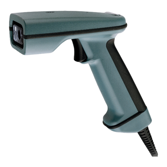
Introduction and Installation About the Hand-Held and Fixed Mount 2D Imager The hand-held and fixed mount 2D Imager is an economical, durable solution for a wide variety of data collection applications. The Imager features the following: • A tough, ergonomic thermoplastic housing for comfort and durability. •... -
Page 14: Unpacking The Imager
Unpacking the Imager Open the carton. The shipping carton or container should contain: IMAGETEAM 4410 Convenience Kit: IMAGETEAM 4410 Hand Held Imager IMAGETEAM 4710 Convenience Kit: IMAGETEAM 4710 Hand Held/Fixed Mount Imager 1 - 2 Universal Power Supply and Power Cable Cable Universal Power Supply and Power Cable... - Page 15 • Check to make sure everything you ordered is present. • Save the shipping container for later storage or shipping. • Check for damage during shipment. Report damage immediately to the carrier who delivered the carton. IMAGETEAM™ 4410/4710 User’s Guide 1 - 3...
-
Page 16: It4410 Imager Identification
IT4410 Imager Identification Model # - 4410XX-XX Manufactured - August 2002 Serial # = P-12-34567 S/W = 34567001/4410 1 - 4 Enlarged View of Label Hand Held IT4410 Imager Bottom View IMAGETEAM™ 4410/4710 User’s Guide... -
Page 17: It4710 Imager Identification
IT4710 Imager Identification Hand Held IT4710 Imager Bottom View ITEM # IT4710 DATE / SN: S / W Rev: Hand Held Products Skaneateles Falls, NEW YORK 13153 IMAGETEAM™ 4410/4710 User’s Guide 1 - 5... -
Page 18: Connecting The Scanner In Keyboard Wedge Mode
The scanner is now connected and ready to communicate with your terminal/PC. You must program the scanner for your interface before bar code data can be transmitted to your terminal/PC. If you are using the scanner as a keyboard wedge, see"Terminal Interface"... -
Page 19: Connecting The Scanner To A Serial Port
Power Supply 4. Turn the terminal/computer power back on. 5. Verify the scanner operation by scanning a bar code from the sample bar code section in the back of this manual. The scanner will beep once. The scanner is now connected and ready to communicate with your terminal/PC. -
Page 20: Reading Techniques
Reading Techniques The hand-held Imager has a view finder that projects a bright red aiming beam that corresponds to the Imager’s horizontal field of view. The aiming beam should be centered over the bar code, but it can be positioned in any direction for a good read. -
Page 21: Chapter 2 - Programming
Programming Introduction Use this section to program the hand-held or fixed mount Imager. This programming section contains the following menuing selections: • General Selections • Terminal Interface Selections • Keyboard Selections • Communication Settings • Imager Selections • Output Selections •... -
Page 22: Reset Factory Settings
Editor formats. One format per line will be printed out. Show Data Formats Show Software Revision All Symbologies If you want to decode all the symbologies allowable for your scanner, scan the All Symbologies On code. All Symbologies All Symbologies 2 - 2... -
Page 23: Revision Selections
Revision Selections Both the following programming codes would not normally be needed unless you have a problem with the unit. An Application Support Representative may request the boot code or power PC revision information in order to trouble shoot a problem. Power PC Revision Boot Code Revision IMAGETEAM™... -
Page 24: Terminal Interface
Chart" on page 2-5 and locate the Terminal ID number for your PC. Scan the Terminal ID bar code below, then scan the numeric bar code(s) on the inside back cover of this manual to program the scanner for your terminal ID> Scan Save to save your selection. -
Page 25: Supported Terminals Chart
Supported Terminals Chart Terminal DELL Fujitsu HHLC (Code 128 Emulation) Midwest Mitak Olivetti Olivetti Reliasys RS-232 TTL Televideo Texas Instruments Toshiba Toshiba Zenith IMAGETEAM™ 4410/4710 User’s Guide Model(s) PC433 SE (Portable PC) Latitude (Portable PC) 486 SLC (Portable PC) Stylistic (Portable PC) PC XT PS/2 25, 30, 77DX2 AT, PS/2 30-286, 50, 55SX, 60, 70,... -
Page 26: Keyboard Country
Save bar code to program the keyboard for your country. As a general rule, the following characters are not supported by the scanner for countries other than the United States: @ | $ # { } [ ] = / ‘ \ < > ~ Country Code Belgium... -
Page 27: Keyboard Style
Keyboard Style This programs keyboard styles, such as Caps Lock and Shift Lock. Default = Regular. Regular is used when you normally have the Caps Lock key off. Caps Lock is used when you normally have the Caps Lock key on. Shift Lock is used when you normally have the Shift Lock key on. -
Page 28: Keyboard Modifiers
Relationships" on page 2-9 for CTRL+ ASCII Values. Default = Off Control + ASCII Mode On Turbo Mode - The scanner sends characters to an IBM AT terminal faster. (For use with IBM AT only.) If the terminal drops characters, do not use Turbo Mode. Default = Off... -
Page 29: Keyboard Function Relationships
Keyboard Function Relationships The following Keyboard Function Code, Hex/ASCII Value, and Full ASCII “CTRL”+ relationships apply to all terminals that can be used with the scanner. Function Code HEX/ASCII Value IMAGETEAM™ 4410/4710 User’s Guide Full ASCII “CTRL” + 2 - 9... -
Page 30: Communication Settings
Communication Settings <Default All RS-232 Communication Settings> Parity Parity provides a means of checking character bit patterns for validity. The Imager can be configured to operate under Mark , Space , Odd , Even , or No ( None ) parity options. The host terminal must be set up for the same parity as the Imager, to ensure reliable communication. -
Page 31: Baud Rate
Baud Rate This sets the baud rate from 300 bits per second to 115,200 bits per second (see next page). Programming baud rate causes the data to be sent at the specified rate. The host terminal must be set to the same baud rate as the Imager to ensure reliable communication. -
Page 32: Word Length Data Bits
Baud Rate, continued 57600 Word Length Data Bits You can set the Word Length at 7 or 8 bits of data per character. If an application requires only ASCII Hex characters 0 through 7F decimal (text, digits, and punctuation), select 7 data bits. For applications requiring use of the full ASCII set, select 8 data bits per character. -
Page 33: Hardware Flow Control
Hardware Flow Control When hardware flow control is On , the software checks for a CTS signal before sending data. This option is useful when your application supports the CTS signal. * Off Software Flow Control This allows control of data transmission from the Imager using software commands from the host device. -
Page 34: Serial Triggering
When serial triggering is turned On , the Imager requires a serial trigger character to activate scanning and decoding. The unit continues to scan and decode until the Trigger Off character turns off the scanner, a time out occurs, or a bar code is decoded. -
Page 35: Trigger Timeout
Note: ‡ Save are required after reading this programming symbol. See "Decimal to Hex to ASCII Conversion Chart" on page 2-36, and the Programming Chart (inside back cover). Trigger Timeout Use this selection to set a timeout (in quarter seconds) of the Imager’s trigger. Once the imager has timed out, it must be triggered again either serially (see "Serial Triggering"... -
Page 36: Power Saving Mode
Note: ‡ required after reading this programming symbol. Refer to the Programming Chart (inside back cover). Power Saving Mode This provides control of the Imager’s power consumption, as follows: Low Power draws low (50%) LED current during image capture, allowing one read attempt only for each trigger pull. -
Page 37: Power Hold Mode
Power Hold Mode Power Hold On keeps the Imager in a ready to read state. To conserve power, this selection may be turned Off and the unit will power down if not used within two minutes. When you are ready to use the Imager again, restore power by pressing the trigger. -
Page 38: Led Flashing
* On Aimer Delay The aimer delay allows a delay time for the operator to aim the scanner before the picture is taken. Use these codes to set the time between when the trigger is pulled and when the picture is taken. During the delay time, the aiming light will appear, but the LEDs won’t turn on until the delay time is over. -
Page 39: Aimer Interval
Every Read , Every Second Read , or Every Third Read . You may also program the scanner to use the aimer every “x” reads, by entering a number from 0 to 999 to indicate “x.”... -
Page 40: Centering
If a bar code is not within the predefined window, it will not be decoded or output by the scanner. If centering is turned on by scanning the On bar code below, the default centering window is a 60 pixel square area in the center of the imager’s field of view. - Page 41 imager’s field of view with the field of view being 640 by 480 pixels. Bottom Default Center Left Right IMAGETEAM™ 4410/4710 User’s Guide 2 - 21...
- Page 42 Top of Centering Window Top of Centering Default (210) Window Bottom of Centering Bottom of Centering Window Default (270) Window Left of Centering Left of Centering Window Default (290) Window Right of Centering Right of Centering Window Window Default (350) 2 - 22 IMAGETEAM™...
-
Page 43: Autotrigger
Stand symbol. (See Scan Stand Symbol that follows.) When a different code is presented, the Imager is triggered to read the new code. Note: The scanner automatically adjusts the illumination LEDs to the lowest light level possible to maintain a good lock on the Scan Stand symbol. -
Page 44: Scan Stand Symbol
Scan Stand Symbol Note: Scan Stand mode does not work when scanner is programmed for the HHLC interface. When a unit is in Scan Stand mode, the LEDs shine at the Scan Stand symbol on the base of the stand which tells it to remain idle. When the Scan Stand symbol is covered, the imager turns the LEDs on at the configured power level (Default High) and attempts to find and decode bar codes in its field of view. -
Page 45: Presentation Lights
Lights Off bar code below. When a bar code is presented to the scanner, the illuminating LEDs turn on to scan the bar code and then turn off when the bar code has been read. Default = Presentation Mode Lights On . -
Page 46: Fast Omni Mode
Fast Omni Mode Normally, the imager searches throughout its whole field of view to determine if a bar code is present. Fast omni-directional mode provides a reduced search pattern that increases the scan rate of the imager. When fast omni mode is enabled, the imager only tries to locate bar codes in the center area of the image. -
Page 47: Power Up Beeper
Beep On Decode If you want the scanner to beep each time it reads a bar code, leave this setting On . If you don’t want it to beep on each read, but do want it to beep for other events, such as error conditions, set this selection to Off . -
Page 48: Intercharacter, Interfunction, And Intermessage Delays
Intercharacter, Interfunction, and Intermessage Delays Some terminals drop information (characters) if data comes through too quickly. Intercharacter, interfunction, and intermessage delays slow the transmission of data increasing data integrity. Each delay is composed of a 5 millisecond step. You can program up to 99 steps (of 5 ms each). -
Page 49: Interfunction Delay
Next, scan the Character to Trigger bar code, then the 2 digit hex value for the ASCII character that trigger the delay (refer to the "Decimal to Hex to ASCII Conversion Chart" on page 2-36). Note: If you make an error while scanning the digits (before scanning Save), scan Discard on the back cover and scan the correct digits and Save again. -
Page 50: Intermessage Delay
Intermessage Delay Note: This selection is valid for keyboard wedge interfaces only. This is a delay of up to 495 milliseconds (in multiples of 5) placed between each scan transmission. You can program up to 99 steps (of 5 ms each). Scan the Intermessage Delay bar code below, then scan the number of steps, and the Save bar code from the inside back cover. -
Page 51: Prefix/Suffix Overview
Prefix/Suffix Overview When a bar code is scanned, additional information is sent to the host computer along with the bar code data. This group of bar code data and additional, user-defined data is called a “message string.” The selections in this section are used to build the user-defined data into the message string. -
Page 52: Adding A Prefix Or Suffix
Adding a Prefix or Suffix 1. Scan the Add Prefix (page 2-34) or Add Suffix symbol (page 2-34). 2. Determine the 2 digit Hex value from the "Symbology Chart" on page 2-35 for the symbology to which you want to apply the prefix or suffix. 3. -
Page 53: Add A Carriage Return Suffix To All Symbologies
Add a Carriage Return Suffix to All Symbologies Scan the following bar code if you wish to add a Carriage Return/Line Feed Suffix to all symbologies at once. This action first clears all current suffixes, then programs a carriage return suffix for all symbologies. Add a Code I.D. -
Page 54: Prefix Entries
Prefix Entries Add Prefix † Suffix Entries Add Suffix † † One or more two digit numbers and Save are required after reading this programming symbol. Refer to the Programming Chart (inside back cover). Exit Selections Save 2 - 34 Clear All Prefixes Clear All Suffixes IMAGETEAM™... -
Page 55: Symbology Chart
Symbology Chart Code Symbology Australian 4 State Aztec Code BC412** BPO 4 State Canadian 4 State Codabar Codablock-F Code 11 Code 39 Code 49 Code 93 Code 128 Code Z** Data Matrix IATA 2 of 5 Note: Prefix/Suffix entries for specific symbologies override the universal (All Symbologies, 99) entry. -
Page 56: Decimal To Hex To Ascii Conversion Chart
Decimal to Hex to ASCII Conversion Chart Dec. ASCII Dec. 2 - 36 ASCII Dec. “ & ‘ < > IMAGETEAM™ 4410/4710 User’s Guide ASCII Dec. ASCII ‘... -
Page 57: Data Format Editor Overview
Refer to the "Supported Terminals Chart" on page 2-5 and locate the Terminal ID number for your PC. Scan three numeric bar codes on the inside back cover to program the scanner for your terminal ID (you must enter 3 digits). For example, scan 0 0 3 for an AT wedge. -
Page 58: Format Editor Commands
Other Programming Selections • Clear One Data Format This deletes one data format for one symbology. If you are clearing the primary format, scan 0. If you are clearing an alternate format, scan 1, 2, or 3, depending on the alternate format you are clearing. Scan the Terminal Type (refer to the "Supported Terminals Chart"... - Page 59 Search Commands F8 Search ahead for “xx” character from current cursor position, leaving cursor pointing to “xx” character. Syntax = F8xx (xx stands for the hex value for an ASCII code, see "Decimal to Hex to ASCII Conversion Chart" on page 2-36.) F9 Search back for “xx”...
-
Page 60: Data Format Editor
Data Format Editor See page 2-37 through page 2-39 for a description of Data Format selections and commands. Enter Data Format † Clear One Data Format † Exit Selections † One or more two digit numbers and Save are required after reading this programming symbol. -
Page 61: Data Formatter
* On/Not Required Require Data Format When Data Formatter is Required , all input data must conform to an edited format or the scanner does not transmit the input data to the host device. Required Show Data Formats Read the Show Data Formats bar code to transmit the existing data formats. -
Page 62: Alternate Data Formats
1, 2, or 3. An alternate format is initiated by scanning one of the 3 alternate format bar codes below. The scanner will scan the next bar code, formatting the data with the selected alternate format, then revert immediately to the primary format. -
Page 63: Output Sequence Overview
Output Sequence Example In this example, you are scanning Code 93, Code 128, and Code 39 bar codes, but you want the scanner to output Code 39 1st, Code 128 2nd, and Code 93 3rd, as shown below. IMAGETEAM™ 4410/4710 User’s Guide... -
Page 64: Require Output Sequence
When it’s On/Not Required , the scanner will attempt to get the output data to conform to an edited sequence, but if it cannot, the scanner transmits all output data to the host device as is. - Page 65 When the output sequence is Off , the bar code data is output to the host as the scanner decodes it. Note: This selection is unavailable when the Multiple Symbols Selection is turned on. Required On/Not Required IMAGETEAM™ 4410/4710 User’s Guide...
-
Page 66: Output Sequence Editor
Discard Current Output Sequence Changes Note: If you want the scanner to beep after each bar code is read, please see "Output Sequence Beeper" on page 2-27. † One or more two digit numbers and Save are required after reading this programming symbol. -
Page 67: Multiple Symbols
Multiple Symbols Note: This feature does not work when the Imager is in Low Power mode. When this programming selection is turned On , it allows you to read multiple symbols with a single pull of the Imager’s trigger. If you press and hold the trigger, aiming the Imager at a series of symbols, it reads unique symbols once, beeping (if turned on) for each read. -
Page 68: Print Weight
Print Weight Print Weight is used to adjust the way the scanner reads Matrix symbols. If a scanner will be seeing consistently heavily printed matrix symbols, then a print weight of 6 may improve the reading performance. For consistently light printing, a print weight of 2 may help. -
Page 69: Video Reverse
Video Reverse Video Reverse is used to allow the imager to read bar codes that are inverted. The “Off” bar code below is an example of this type of bar code. If additional menuing is required, Video Reverse must be disabled to read the menu bar codes and then re-enabled after menuing is completed. - Page 70 2 - 50 IMAGETEAM™ 4410/4710 User’s Guide...
-
Page 71: Chapter 3 - Symbologies
Symbologies Introduction Use this section to program the hand-held Imager. This programming section contains the following menuing selections: • Linear Symbology Selections • Stacked Symbology Selections • Postal Symbology Selections • 2D Matrix Symbology Selections • Diagnostics IMAGETEAM™ 4410/4710 User’s Guide 3 - 1... -
Page 72: Codabar
If the data length of the scanned bar code doesn’t match the valid reading length, the scanner will not read the symbol. You may wish to set the same value for minimum and maximum length to force the scanner to read fixed length bar code data. -
Page 73: Linear Symbologies
Codabar bar codes printed with a check character, but will not transmit the check character with the scanned data. When Check Character is set to Validate, And Transmit , the scanner will only read Codabar bar codes printed with a check character, and will transmit this character at the end of the scanned data. -
Page 74: Code 39
Linear Symbologies Code 39 < Default All Code 39 Settings > Code 39 * On Start/Stop Characters Start/Stop characters identify the leading and trailing ends of the bar code. You may either transmit, or not transmit Start/Stop characters. * Don’t Transmit Transmit 3 - 4 IMAGETEAM™... -
Page 75: Message Length
If the data length of the scanned bar code doesn’t match the valid reading length, the scanner will not read the symbol. You may wish to set the same value for minimum and maximum length to force the scanner to read fixed length bar code data. -
Page 76: Check Character
Code 39 bar codes printed with a check character, but will not transmit the check character with the scanned data. When Check Character is set to Validate, And Transmit , the scanner will only read Code 39 bar codes printed with a check character, and will transmit this character at the end of the scanned data.will transmit this character at the end of... -
Page 77: Code 11
If the data length of the scanned bar code doesn’t match the valid reading length, the scanner will not read the symbol. You may wish to set the same value for minimum and maximum length to force the scanner to read fixed length bar code data. -
Page 78: Check Digits Required
Linear Symbologies Code 11, continued Check Digits Required This option sets whether 1 or 2 check digits are required with Code 11 bar codes. * Two Check Digits One Check Digit 3 - 8 IMAGETEAM™ 4410/4710 User’s Guide... -
Page 79: Interleaved 2 Of 5
If the data length of the scanned bar code doesn’t match the valid reading length, the scanner will not read the symbol. You may wish to set the same value for minimum and maximum length to force the scanner to read fixed length bar code data. -
Page 80: Check Digit
Interleaved 2 of 5 bar codes printed with a check digit, but will not transmit the check digit with the scanned data. When Check Digit is set to Validate, And Transmit , the scanner will only read Interleaved 2 of 5 bar codes printed with a check digit, and will transmit this digit at the end of the scanned data. -
Page 81: Iata 2 Of 5
If the data length of the scanned bar code doesn’t match the valid reading length, the scanner will not read the symbol. You may wish to set the same value for minimum and maximum length to force the scanner to read fixed length bar code data. -
Page 82: Msi
If the data length of the scanned bar code doesn’t match the valid reading length, the scanner will not read the symbol. You may wish to set the same value for minimum and maximum length to force the scanner to read fixed length bar code data. -
Page 83: Check Digit
Linear Symbologies MSI, continued Check Digit This selection allows you to specify whether the check digit should be transmitted at the end of the scanned data. * Don’t Transmit Transmit Check Digit Check Digit IMAGETEAM™ 4410/4710 User’s Guide 3 - 13... -
Page 84: Message Length
If the data length of the scanned bar code doesn’t match the valid reading length, the scanner will not read the symbol. You may wish to set the same value for minimum and maximum length to force the scanner to read fixed length bar code data. This helps reduce the chances of a misread. -
Page 85: Code 93
If the data length of the scanned bar code doesn’t match the valid reading length, the scanner will not read the symbol. You may wish to set the same value for minimum and maximum length to force the scanner to read fixed length bar code data. -
Page 86: Isbt
Linear Symbologies ISBT Scan the On code below if you wish to decode ISBT bar codes. (ISBT codes are a combination of multiple linear symbols used to mark blood bags.) * Off 3 - 16 IMAGETEAM™ 4410/4710 User’s Guide... -
Page 87: Ean/Jan 8
Linear Symbologies EAN/JAN 8 < Default All EAN/JAN 8 Settings > EAN/JAN 8 * Off Check Digit This selection allows you to specify whether the check digit should be transmitted at the end of the scanned data. * Don’t Transmit Transmit Check Digit Check Digit... -
Page 88: Ean/Jan 8 Addenda
You can add 2 or 5 digits to the end of all scanned EAN/JAN 8 data. 2 Digit Addenda On 5 Digit Addenda On EAN/JAN 8 Addenda Required When Addenda Required is used, the scanner will only read EAN/JAN 8 bar codes that have addenda. Required EAN/JAN 8 Addenda Separator When this feature is On , there is a space between the data from the bar code and the data from the addenda. -
Page 89: Ean/Jan 13
Linear Symbologies EAN/JAN 13 < Default all EAN/JAN 13 Settings > EAN/JAN 13 * On Check Digit This selection allows you to specify whether the check digit should be transmitted at the end of the scanned data. * Don’t Transmit Transmit Check Digit Check Digit... -
Page 90: Ean/Jan 13 Addenda
You can add 2 or 5 digits to the end of all scanned EAN/JAN 13 data. 2 Digit Addenda On 5 Digit Addenda On EAN/JAN 13 Addenda Required When Addenda Required is used, the scanner will only read EAN/JAN 13 bar codes that have addenda. Required EAN/JAN 13 Addenda Separator When this feature is On , there is a space between the data from the bar code and the data from the addenda. -
Page 91: Upc A
Linear Symbologies UPC A < Default All UPC A Settings > UPC A * On Check Digit This selection allows you to specify whether the check digit should be transmitted at the end of the scanned data. * Don’t Transmit Transmit Check Digit Check Digit... -
Page 92: Upc A Addenda
You can add 2 or 5 digits to the end of all scanned UPC A data. 2 Digit Addenda On 5 Digit Addenda On UPC A Addenda Required When Addenda Required is used, the scanner will only read UPC A bar codes that have addenda. Required UPC A Addenda Separator When this feature is On , there is a space between the data from the bar code and the data from the addenda. -
Page 93: Upc E0
Linear Symbologies UPC E0 < Default All UPC E0 Settings > UPC E0 Most UPC bar codes lead with the 0 number system. For these codes, use the UPC E0 selection. If you need to read codes that lead with the 1 number system, use the UPC E1 selection (see "UPC E1"... -
Page 94: Version E Expand
Linear Symbologies UPC E0, continued Version E Expand Version E Expand, expands the UPC-E code to the 12 digit, UPC-A format. Expand UPC E1 Most UPC bar codes lead with the 0 number system. For these codes, use the UPC E0 selection (see "UPC E0" on page 3-23). If you need to read codes that lead with the 1 number system, use the UPC E1 selection. -
Page 95: Upc E0/E1 Addenda Required
Linear Symbologies UPC E0/E1 Addenda Required When Addenda Required is used, the scanner will only read UPC E0 and E1 bar codes that have addenda. Required UPC E0/E1 Addenda Separator When this feature is On , there is a space between the data from the bar code and the data from the addenda. -
Page 96: Rss-14
Linear Symbologies RSS-14 < Default All RSS-14 Settings > RSS-14 Reduced Space Symbology (RSS) is a family of linear bar codes which meets restricted space requirements, while still providing full product identification. RSS-14 On * RSS-14 RSS-14 Limited < Default All RSS-14 Limited Settings > RSS-14 Limited * RSS-14 Limited RSS-14 Limited On... -
Page 97: Rss-14 Expanded
If the data length of the scanned bar code doesn’t match the valid reading length, the scanner will not read the symbol. You may wish to set the same value for minimum and maximum length to force the scanner to read fixed length bar code data. -
Page 98: Codablock
If the data length of the scanned bar code doesn’t match the valid reading length, the scanner will not read the symbol. You may wish to set the same value for minimum and maximum length to force the scanner to read fixed length bar code data. -
Page 99: Stacked Symbologies
If the data length of the scanned bar code doesn’t match the valid reading length, the scanner will not read the symbol. You may wish to set the same value for minimum and maximum length to force the scanner to read fixed length bar code data. -
Page 100: Micropdf417
If the data length of the scanned bar code doesn’t match the valid reading length, the scanner will not read the symbol. You may wish to set the same value for minimum and maximum length to force the scanner to read fixed length bar code data. -
Page 101: Code 49
If the data length of the scanned bar code doesn’t match the valid reading length, the scanner will not read the symbol. You may wish to set the same value for minimum and maximum length to force the scanner to read fixed length bar code data. -
Page 102: Ean•Ucc Composite Codes
If the data length of the scanned bar code doesn’t match the valid reading length, the scanner will not read the symbol. You may wish to set the same value for minimum and maximum length to force the scanner to read fixed length bar code data. -
Page 103: Tlc39
Stacked Symbologies TLC39 TLC39 stands for TCIF Linked Code 39 (where TCIF stands for Telecommunications Industry Forum). This code is a composite code since it has a Code 39 linear component and a MicroPDF417 stacked code component. All bar code readers are capable of reading the Code 39 linear component. In fact, the linear component may be decoded as Code 39 even if TLC39 is disabled. -
Page 104: Postal Symbologies
Postal Symbologies Note: Note: when reading a postal symbology, all other postal symbologies should be turned off. U.S. Postal Service POSTNET Code Check Digit This selection allows you to specify whether the check digit should be transmitted at the end of the scanned data. Transmit Check Digit Planet Code... -
Page 105: British Post Office 4 State Code
Postal Symbologies British Post Office 4 State Code Canadian 4 State Code Dutch Postal Code Australian 4 State Code Japanese Postal Service IMAGETEAM™ 4410/4710 User’s Guide * Off * Off * Off * Off * Off 3 - 35... -
Page 106: Qr Code
If the data length of the scanned bar code doesn’t match the valid reading length, the scanner will not read the symbol. You may wish to set the same value for minimum and maximum length to force the scanner to read fixed length bar code data. -
Page 107: Data Matrix
If the data length of the scanned bar code doesn’t match the valid reading length, the scanner will not read the symbol. You may wish to set the same value for minimum and maximum length to force the scanner to read fixed length bar code data. -
Page 108: Maxicode
If the data length of the scanned bar code doesn’t match the valid reading length, the scanner will not read the symbol. You may wish to set the same value for minimum and maximum length to force the scanner to read fixed length bar code data. -
Page 109: Structured Carrier Message Only
MaxiCodes, turn Structured Carrier Message Only On . Turn this feature on if you are trying to read a damaged Maxicode. The scanner may be able to extract just the structured carrier message if the center portion of the code is intact. -
Page 110: Aztec Code
If the data length of the scanned bar code doesn’t match the valid reading length, the scanner will not read the symbol. You may wish to set the same value for minimum and maximum length to force the scanner to read fixed length bar code data. -
Page 111: Test Menu
You may wish to use this feature in conjunction with Quick*View (see page 7-1). Note: Note: This feature should not be used during normal scanner operation. Note: 2D PQA (Print Quality Assessment) Two-dimensional Print Quality Assessment (2D PQA) is a feature of Hand Held Products’s image readers where the data from the successful read of a 2D bar... - Page 112 3 - 42 IMAGETEAM™ 4410/4710 User’s Guide...
-
Page 113: Chapter 4 - Ocr Programming
OCR format you intend to read. See "OCR" on page 4-2 for programming codes that will enable your scanner to read OCR-A, OCR-B or U.S. Currency fonts. See "Creating OCR Templates" on page 4-4 if you want to create a custom “template,”... -
Page 114: Ocr
Default All OCR Settings turns off all OCR capability in the scanner, so the scanner will be able to scan linear, stacked, matrix, and composite bar codes, but not OCR fonts. In addition, any OCR templates you have created are erased. -
Page 115: Ocr Direction
All OCR Off turns off all OCR capability in the scanner, so the scanner will be able to scan linear, stacked, matrix, and composite bar codes, but not OCR fonts. However, any OCR templates you have created will be retained in memory. -
Page 116: Creating Ocr Templates
You can create a custom “template,” or character string that defines the length and content of OCR strings that will be read with your scanner. There are several choices when creating a custom template for your application. You can create a template for a single format, you can string together several formats, and you can create a template for a user-defined variable. - Page 117 To create this template, you would scan the Enter OCR Template symbol (page 4-9), then scan the d from the OCR Programming Chart after the Sample Codes in the back of this manual 8 times. Scan Save OCR Template (page 4-9). This would let you read any string of 8 digits, for example: 3.
-
Page 118: Stringing Together Multiple Formats (Creating "Or" Statements)
Stringing Together Multiple Formats (Creating “Or” Statements) You may want to program the scanner to accept many OCR formats. To do this, you would string together each format with a “t.” This tells the scanner to read optical characters that match any one of the formats in the template. -
Page 119: Adding An Ocr Check Character
A, B, or C trailing. So you would be able to read: Adding an OCR Check Character You may want to program the scanner to read OCR strings that have a check character. The IT4410/4710 reads and strips out the OCR check character created using a modulo 10 or modulo 36 table. -
Page 120: Reading Multi-Row Ocr
Reading Multi-Row OCR The IT4410/4710 is capable of decoding multi-row OCR text. Consider the following example. This example shows serial commands as would be entered using Quick*View. Example G: You need to read multiple rows of OCR data as shown below: To read the first row of OCR data, you would menu the following template: This template is the default OCR template. -
Page 121: Ocr Template Codes
OCR Template Codes † Enter OCR Template Enter User- Enter User- Defined Variable Defined Variable † † “g” “h” OCR Modulo 10 Check OCR Modulo 36 Character Check Character † One or more two-digit numbers and Save are required after reading this programming symbol. - Page 122 4 - 10 IMAGETEAM™ 4410/4710 User’s Guide...
-
Page 123: Default Charts
Default Charts The following chart lists the factory default settings (indicated by a “✱” on the programming menu pages). Parameter Terminal ID - Keyboard Wedge Terminal ID - True RS-232 Keyboard Country Keyboard Style Keyboard Modifiers Communication (RS-232) Selections Parity Baud Rate Word Length Data Bits Word Length Stop Bits... -
Page 124: Prefix/Suffix Selections
Parameter Presentation Re-Trigger Delay Presentation Lights Beeper Volume Power Up Beeper Output Sequence Beeper Beep On Decode Intercharacter Delay User Specified Intercharacter Delay Interfunction Delay Intermessage Delay Prefix/Suffix Selections Prefix Suffix Data Formatter Selections Data Format Data Formatter Require Data Format Output Sequence Selections Multiple Symbols Require Output Sequence... - Page 125 Parameter Code 11 Message Length Check Digits Required Interleaved 2 of 5 Message Length Check Digit IATA 2 of 5 Message Length Message Length Check Digit Code 93 Message Length Code 128 Message Length ISBT EAN/JAN 8 Check Digit EAN/JAN 8 Addenda EAN/JAN 8 Addenda Required EAN/JAN 8 Addenda Separator EAN/JAN 13...
-
Page 126: Postal Symbology Selections
Parameter Version E Expand UPC E1 UPC E0/E1 Addenda UPC E0/E1 Addenda Required UPC E0/E1 Addenda Separator RSS-14 RSS-14 Limited RSS-14 Expanded RSS-14 Expanded Message Length Codablock Message Length PDF417 Message Length MicroPDF417 Message Length Code 49 Message Length EAN•UCC Composite Codes Message Length Postal Symbology Selections... -
Page 127: Ocr Selections
Parameter Message Length SCM Only Aztec Code Message Length OCR Selections OCR-A OCR-B U.S. Currency IMAGETEAM™ 4410/4710 User’s Guide Default Setting Min = 1, Max = 150 Min = 1, Max = 3750 Page page 3-38 page 3-39 page 3-40 page 3-40 page 4-2 page 4-2... - Page 128 5 - 6 IMAGETEAM™ 4410/4710 User’s Guide...
-
Page 129: Chapter 6 - Software Development Kit
The IMAGETEAM™ Software Development Kit (SDK) provides a set of libraries, tools, and sample source code to help software developers create an interface between their host system and a Hand Held Products image/data capture device. The SDK consists of: • The API Definition and Documentation •... - Page 130 6 - 2 IMAGETEAM™ 4410/4710 User’s Guide...
-
Page 131: Chapter 7 - Quick*View
5. To start the Quick*View program, from the Start Menu click on Programs, Quickview, QuickView (32 Bit). Installing Quick*View from the Web 1. Access the Hand Held Products web site at www.handheld.com. 2. Click in the Quick Search text box and enter Quick*View. 3. Click on Search Now. -
Page 132: Temporary Quick*View Configuration
Temporary Quick*View Configuration For a quick download communication configuration, scan the Quick*View bar code and the scanner will be temporarily configured for Quick*View settings. Note: If you have a unit capable of keyboard wedge mode, scan the bar code below and the unit will communicate in RS-232 mode, allowing it to work with Quick*View. -
Page 133: Using The Quick*View Software
Using the Quick*View Software Upon startup, the Quick*View splash screen appears for approximately three seconds. Quick*View will then attempt to establish communications with the Imager. If Communication Cannot Be Established This message appears if communication cannot be established: Quick*View defaults to com 1 as the communications port. If you have plugged the Imager into another com port, you must Cancel out of this message. -
Page 134: Scan Data Window
Scan Data Window Once successful communication has been established, you can scan codes and display the bar code data in a window. Select View - Scan Data Window. As you scan bar codes, the data appears in the Serial Scan Data Window. You can alter the font in this window by using the Font button, or clear all data in the window with the Clear button. - Page 135 Snapshot You may also use the IMAGETEAM 4410/4710 to capture an image. Click on Device - Snapshot, or click on the camera icon in the button bar to activate this feature. Select the resolution you wish to use for this image, either Full, Half or Quarter Resolution.
-
Page 136: Saving An Image File
Snapshot, continued Pull the Imager’s trigger to capture an image. Captured images appear in the Quick*View window. As you move the mouse over the image, the cursor changes to a magnifying glass. Left click to zoom in to the image, right click to zoom out. Saving an Image File If you wish to save the file as a bitmap, click on File - Save As. -
Page 137: Open Com Port
Open Com Port If you wish to open a com port which does not have a device attached, you can do so by selecting File - Open Com Port. This dialog box appears: Click on the arrows to select the Baud Rate, Parity, and Data Bits for the com port you wish to open. -
Page 138: Load New Imager Software
Load New Imager Software If you need to upgrade the Imager’s software, you can load a new software file into the Imager’s ROM. Click on Device - Load Firmware File into ROM or click on the lightning flash icon in the button bar. Flash icon You will be... -
Page 139: Serial Programming Commands
RS-232 Serial Commands Click on View - Serial Command Window to display the Command Center window which allows you to enter serial commands to the Imager. Click on View - Scan Data Window to open a window which displays serial data in a text format. -
Page 140: Command Center Buttons
Responses The Imager responds to serial commands with one of three responses: ACK Indicates a good command which has been processed. ENQ Indicates a bad command. NAK Indicates the command was good, but the entry was out of the allowable range, e.g., an entry for a minimum message length of 100 when the field will only accept 2 characters. -
Page 141: Examples Of Query Commands
Query Commands Several special characters can be used to query the Imager about its settings. What is the default value for the setting(s). What is the Imager’s current value for the setting(s). What is the range of possible values for the setting(s). (The Imager’s response uses a dash (-) to indicate a continuous range of values. -
Page 142: Trigger Commands
Deactivate SYN U CR The scanner scans until a bar code has been read, until the deactivate command is sent, or until the serial timeout has been reached. See "Trigger Timeout" on page 2-15 for a description and the serial command on page 7-15. -
Page 143: Button Bar
Display firmware revision Start Visual Menu software* Note: *This icon only appears if you have Visual Menu software installed. Visual Menu is available free of charge from the Hand Held Products website at www.handheld.com. IMAGETEAM™ 4410/4710 User’s Guide 7 - 13... -
Page 144: Serial Programming Commands
Serial Programming Commands Selection Factory Default Settings Status Check Show Software Revision Show Data Formats Enable All Symbologies Disable All Symbologies Output Selections Power PC Revision Boot Code Revision Terminal ID Keyboard Country Keyboard Style Keyboard Modifiers Communication Settings *Default All RS-232 Communication Settings Parity 7 - 14... -
Page 145: Imager Selections
Selection Baud Rate Word Length Data Bits Word Length Stop Bits Hardware Flow Control Software Flow Control Serial Triggering Trigger Timeout Hardware Triggering Imager Selections Power Saving Mode IMAGETEAM™ 4410/4710 User’s Guide Setting * Indicates Default Setting *38400 BPS 300 BPS 600 BPS 1200 BPS 2400 BPS... -
Page 146: Output Selections
Selection Power Hold Mode LED Power LED Flashing Aimer Delay Aimer Interval Centering Scan Stand Presentation Mode Presentation Re-Trigger Delay Presentation Lights Presentation Default Output Selections Beeper Volume 7 - 16 Setting * Indicates Default Setting *Off *High *Off (no delay) 200 milliseconds 400 milliseconds *Every Read... - Page 147 Selection Power Up Beeper Output Sequence Beeper Beep On Decode Beeper Volume Beeper Default Intercharacter Delay User Specified Intercharacter Delay Interfunction Delay Intermessage Delay Prefix/Suffix Selections Add CR Suffix to All Symbologies Add Code I.D. Prefix to All Symbologies Add AIM I.D. Prefix to All Symbologies Prefix Save Current Prefix Changes Discard Current Prefix Changes...
- Page 148 Selection Data Formatter Require Data Format Show Data Formats Alternate Data Formats Output Sequence Selections Require Output Sequence Output Sequence Editor Save Current Sequence Changes Discard Current Sequence Changes Multiple Symbols No Read Print Weight Set Print Weight Video Reverse Function Code Transmit Linear Symbology Selections Codabar...
- Page 149 Selection Codabar Check Char. Code 39 Code 39 Code 39 Start/Stop Char. Code 39 Full ASCII Code 39 Message Length Code 39 Check Char. Code 39 Mesa Composite Code 11 Code 11 Code 11 Message Length Code 11 Check Digits Required Interleaved 2 of 5 Interleaved 2 of 5...
- Page 150 Selection Interleaved 2 of 5 Check Digit Interleaved 2 of 5 Mesa Com- posite IATA 2 of 5 IATA 2 of 5 IATA 2 of 5 Message Length MSI Check Digit Code 93 Code 93 Code 93 Message Length Code 93 Mesa Composite Code 128 Code 128 Code 128 Message Length...
- Page 151 Selection Code 128 Mesa Composite EAN/JAN 8 EAN/JAN 8 EAN/JAN 8 Check Digit EAN/JAN 8 2 Digit Addenda EAN/JAN 8 5 Digit Addenda EAN/JAN 8 Addenda Required EAN/JAN 8 Addenda Separator EAN/JAN 13 EAN/JAN 13 EAN/JAN 13 Check Digit EAN/JAN 13 2 Digit Addenda EAN/JAN 13 5 Digit Addenda EAN/JAN 13 Addenda Required...
- Page 152 Selection UPC A Check Digit UPC A Number System UPC A 2 Digit Addenda UPC A 5 Digit Addenda UPC A Addenda Required UPC A Addenda Separator UPC E0 UPC E0 UPC E0 Check Digit UPC E0 Number System UPC E0 Version E Expand UPC E1 UPC E0/E1 2 Digit Addenda UPC E0/E1 5 Digit Addenda...
-
Page 153: Stacked Symbology Selections
Selection RSS-14 RSS-14 Limited RSS-14 Limited RSS-14 Limited RSS Expanded RSS Expanded Msg. Length Stacked Symbology Selections Codablock Codablock Codablock Msg. Length PDF417 PDF417 PDF417 Message Length MicroPDF417 MicroPDF417 MicroPDF417 Message Length Code 49 Code 49 IMAGETEAM™ 4410/4710 User’s Guide Setting * Indicates Default Setting *Off... - Page 154 Selection Code 49 Msg. Length • UCC Composite Codes • UCC Composite Msg. Length TLC39 Postal Symbology Selections POSTNET Code (USPS) POSTNET Check Digit BPO 4 State Code (BPO) Canadian 4 State Code Dutch Code Australian 4 State Code Japanese Postal Code Planet Code Planet Check Digit 2D Matrix Symbology Selections...
- Page 155 Selection Data Matrix Settings Data Matrix Data Matrix Msg. Length MaxiCode Settings MaxiCode MaxiCode Msg. Length SCM Only Aztec Code Settings Aztec Code Aztec Code Msg. Length Test Menu Print Quality Assessment IMAGETEAM™ 4410/4710 User’s Guide Setting * Indicates Default Setting *Default All Data Matrix Settings* Minimum...
- Page 156 Selection 1. XX = decimal value. Trigger on is defaulted to 18 and trigger off is defaulted to 20. 2. See the SDK User’s Guide for the commands needed to utilize Hardware Triggering. 7 - 26 Setting * Indicates Default Setting *Default All OCR Settings* *All OCR Off OCR-A On...
-
Page 157: Imaging Commands
IMGSHP command. The image ship command has many different modifiers that can be used to change the look of the image that is output by the scanner. The default image file format used by IMGSHP is a gray scale KIM. -
Page 158: Image Capture/Ship And Image Get Commands
IMGSHP command (page 7-27) also are available for the IMGCAP command to change the look of the image that is output by the scanner. When using the IMGCAP command, the imager is optimized to capture images of close objects (e.g., signatures, address labels). -
Page 159: Image Cropping/Shipping Example
Upon the receipt of the bar code data, the host application sends the “IMGBOX” command, which tells the scanner to output only the area of the image corresponding to the signature capture box. The scanner also automatically adjusts for aspect ratio and distortion issues that arise due to scanner skew with respect to the bar code. -
Page 160: Imgbox Modifiers
Using this method, intelligent signature capture always outputs the correct image size and resolution no matter the distance at which the scanner is held from the bar code, assuming that the entire signature capture area is within the scanner’s field of view. - Page 161 F - File Format: 0F - KIM format, default 1F - TIFF Binary 2F - TIFF Binary Group 4 Compressed 3F - TIFF Gray scale 4F - Uncompressed Binary 5F - Uncompressed Gray scale 6F - JPEG image 7F - Outlined image IMAGETEAM™...
- Page 162 7 - 32 IMAGETEAM™ 4410/4710 User’s Guide...
- Page 163 IMAGETEAM™ 4410/4710 User’s Guide 7 - 33...
- Page 164 7 - 34 IMAGETEAM™ 4410/4710 User’s Guide...
-
Page 165: Chapter 8 - Visual Menu
Visual Menu Introduction Visual Menu provides the ability to configure a scanning device by connecting the scanner to the com port of a PC. Visual Menu allows you to download upgrades to a scanner’s firmware, change programmed parameters, and create and print programming bar codes. -
Page 166: Temporary Visual Menu Configuration
Visual Menu. To convert the scanner back to keyboard wedge communication, cycle the power. Installing Visual Menu from the Web 1. Access the Hand Held Products web site at www.handheld.com. 2. Click on the Quick Search text box and enter Visual Menu. 3. Click on Search Now. -
Page 167: Chapter 9 - Interface Keys
Interface Keys Supported Interface Keys IMAGETEAM™ 4410/4710 User’s Guide IBM AT/XT and PS/2 IBM XTs and Compatibles, Compatibles WYSE PC/AT Reserved Reserved Enter (KP) CR/Enter Caps Lock Caps Lock ALT make Reserved ALT break Reserved CTRL make Reserved CTRL break Reserved CR/Enter CR/Enter... - Page 168 Supported Interface Keys IBM 3191/92, 3471/72, 3196/97, 3476/77, Telex (all models) Supported Interface Keys 9 - 2 IBM AT/XT and PS/2 IBM XTs and Compatibles, Compatibles WYSE PC/AT Reserved IBM, Memorex Telex (102) Reserved Enter IMAGETEAM™ 4410/4710 User’s Guide IBM, DDC, Memorex Telex, Harris Memorex...
- Page 169 Supported Interface Keys IMAGETEAM™ 4410/4710 User’s Guide IBM, Memorex Telex (102) New Line Tab/Field Forward Delete Field Exit Insert Clear Error Reset Home Print Back Space Back Tab Memorex Telex (88) New Line Field Forward Field Forward Reserved Field Forward Delete New Line Insert...
- Page 170 IBM, Memorex Supported Interface Keys Telex (102) *. IBM 3196/97, 3476/77, 3191/92, 3471/72, Memorex Telex (all mod- els) with 102 key keyboards **.Memorex Telex with 88 key keyboards Supported Esprit 200, 400 Interface Keys ANSI Reserved New Line New Line New Line Escape Insert...
- Page 171 Supported Interface Keys IMAGETEAM™ 4410/4710 User’s Guide Esprit 200, 400 Esprit 200, 400 ANSI ASCII Back Space Back Space Back Tab Back Tab Esprit 200, 400 Print Back Space Back Tab 9 - 5...
- Page 172 9 - 6 IMAGETEAM™ 4410/4710 User’s Guide...
-
Page 173: Chapter 10 - Product Specifications & Pinouts
Product Specifications & Pinouts Product Specifications - IT4410 Parameter Dimensions Length Height Width Weight Illumination Source Aiming Pattern Source Focal Point (focus) Long Range High Density High Density10 Field of View Long Range High Density High Density10 Rotational Sensitivity Viewing Angle Motion Sensitivity Ambient Light Video Image... -
Page 174: Product Specifications - It4710
Parameter ESD Sensitivity Agency Compliance Product Specifications - IT4710 Parameter Dimensions Length Height Width Weight Illumination Source Aiming Pattern Source Focal Point (focus) Long Range High Density High Density10 Field of View Long Range High Density High Density10 Rotational Sensitivity Viewing Angle Motion Sensitivity Ambient Light... - Page 175 Parameter Current Draw Low Power Mode Medium Power Mode High Power Mode Temperature Ranges Humidity Mechanical Shock ESD Sensitivity Agency Compliance IMAGETEAM™ 4410/4710 User’s Guide Specification Average @ 5 VDC - 40mA Average @ 5 VDC - 125mA Average @ 5 VDC - 175mA Operating 32°...
-
Page 176: Depth Of Field Charts
Depth of Field Charts All depth of field measurements are made from the IT4410/4710 lens plate, which is .100” (.25 cm) from the front surface of the IT4410/4710 window. Depth of Field for High Density Imager (2" Nominal Focus) Code Size QR 6.6 mil (0.017 cm) Data Matrix 6.6 mil (0.017 cm) Linear 4 mil (0.01 cm) - Page 177 Depth of Field for LX Imager (7" Nominal Focus) Code Size MaxiCode 35 mil (0.089 cm) Data Matrix 15 mil (0.038 cm) PDF 10 mil (0.025 cm) PDF 8 mil (0.020 cm) PDF 6.6 mil (0.017 cm) Code 39 15 mil (0.038 cm) Code 39 10 mil (0.025 cm) Code 39 8 mil (0.020 cm) UPC 13 mil (0.033 cm)
-
Page 178: Cable Pinouts
Imager.Interface cables normally supplied with the Imager are terminated with a 10 pin modular plug (P1) and a 9 pin Type D connector (P3) that is compatible with all Hand Held Products decoders and terminals. See chart below. (The power pigtail applies to serial wedge cable, which is not shown.) -
Page 179: Connector Part Numbers
P/N: 21020-0075 (2” length specified. Various lengths available.) Optics Connector P/N: 52559-2290 (straight) P/N: 52437-2291 (right angle) Optics-to-Decoder Board Flex Strip P/N: 21020-0229 (2” length specified. Contact Hand Held Products if other lengths are needed) IMAGETEAM™ 4410/4710 User’s Guide 10 - 7... -
Page 180: It4410 Dimensions
IT4410 Dimensions 2.49 in [6.32 cm] 3/4 View 10 - 8 6.06 in [15.38 cm] 5.62 in [14.28 cm] 1.07 in [2.72 cm] Side View IMAGETEAM™ 4410/4710 User’s Guide Top View 1.53 in [4.01 cm] Front View... -
Page 181: It4710 Dimensions
IT4710 Dimensions 4.83 in. (12.27 cm) 2.49 in. Top View (6.32 cm) 1.83 in. 1.53 in. (4.65 cm) (4.01 cm) Front View 1.63 in. (4.14 cm) 1.076 in. (2.73 cm) Side View .538 in. (1.37 cm) .630 in. (1.60 cm) M4 threaded insert .25 in. - Page 182 10 - 10 IMAGETEAM™ 4410/4710 User’s Guide...
-
Page 183: Maintenance And Troubleshooting
Maintenance & Troubleshooting Repairs Repairs and/or upgrades are not to be performed on this product. These services are to be performed only by an authorized service center. See page 12- 1 for further information. Maintenance The IMAGETEAM 4410/IT4710 Imager provides reliable and efficient operation with a minimum of care. -
Page 184: Examining The Imager's Housing
Examining the Imager’s Housing Routinely examine the Imager’s housing for signs of damage. A damaged housing may cause the internal components to move and may result in a malfunctioning Imager. Replacing the Interface Cable The standard interface cable is attached to the Imager with an 10-pin modular connector. -
Page 185: Troubleshooting
To Replace the IT4710 Interface Cable: 1. Turn the power to the host system OFF. 2. Disconnect the Imager’s cable from the terminal or computer. 3. Insert a small, flat head screwdriver into the slot between the cable and the back end of the housing. - Page 186 11 - 4 IMAGETEAM™ 4410/4710 User’s Guide...
-
Page 187: Chapter 12 - Customer Support
Hand Held Products provides service for all its products through service centers throughout the world. To obtain warranty or non-warranty service, return the unit to Hand Held Products (postage paid) with a copy of the dated purchase record attached. Contact the appropriate location below to obtain a Return Material Authorization number (RMA #) before returning the product. -
Page 188: Online Product Service And Repair Assistance
(C) static electricity or electro-static discharge, (D) operation under conditions beyond the specified operating parameters, or (E) repair or service of the product by anyone other than Hand Held Products or its authorized representatives. 12 - 2... - Page 189 No product will be accepted by Hand Held Products without a Return Materials Authorization, which may be obtained by contacting Hand Held Products. In the event that the product is returned to Hand Held Products or its authorized service center within the Warranty Period and Hand...
- Page 190 12 - 4 IMAGETEAM™ 4410/4710 User’s Guide...
- Page 191 Serial Commands Code 49 Selections Serial Commands Code 93 Selections Serial Commands Code I.D. Prefix Add to all Symbologies Communication Settings Connecting the scanner Keyboard wedge Serial port Conversion Chart Decimal to Hex to ASCII Data Format Require Serial Command...
- Page 192 Data Formats Show 2-2, 2-41 Serial Command Data Formatter 2-41 Serial Command Data Matrix Selections Serial Commands Decimal to Hex to ASCII Conversion Chart 2-36 Default Settings Dimensions 10-8 Disable All Symbologies Serial Command EAN/JAN 13 Selections Serial Commands EAN/JAN 8 Selections Serial Commands EAN•UCC Composite Codes Enable All Symbologies...
- Page 193 Micro PDF Selections Serial Commands MicroPDF Selections Money reading serial numbers Multiple Symbols Serial Command No Read 2-47 Serial Command OCR Programming Online Programming Open Com Port Output Sequence Descriptions and Examples Require 2-44 Serial Command Output Sequence Editor Serial Command Overview Parity 2-10...
- Page 194 Reporting Firmware Revision Using Quick*View Require Data Format 2-41 Serial Command Require Output Sequence Serial Command Reset Factory Settings Revision Selections Serial Commands RS-232 Communication Serial Command RSS-14 Selections 3-26 Serial Commands Scan Data Window Scan Stand Selections Serial Command SCM Selections Serial Commands Serial Programming Commands...
- Page 195 Require Data Format Require Output Sequence RS-232 Communication RSS-14 7-22 Scan Stand 7-16 SCM Selections 7-25 Serial Triggering Set Print Weight 7-18 Show Data Formats Show Software Revision Software Flow Control Suffix 7-17 Terminal ID 7-14 UPC A Selections UPC E0 Selections UPC E1 Selections Word Length Data Bits Word Length Stop Bits...
- Page 196 Index - 6...
-
Page 197: Sample Symbols
Sample Symbols UPC A Interleaved 2 of 5 0 123456 7890 1234567890 Code 128 Code 128 EAN 13 9 780330 290951 Code 39 BC321 Codabar A13579B IMAGETEAM™ 4410/4710 User’s Guide... - Page 198 Sample Symbols PDF417 Car Registration Postnet Zip Code Code 49 1234567890 Data Matrix OCR-A Sample 55836540 Test Symbol OCR-B Sample QR Code Numbers IMAGETEAM™ 4410/4710 User’s Guide...
- Page 199 Sample Symbols Aztec Package Label Aztec Mesa Code Test Message MaxiCode Test Message Micro PDF417 Test Message IMAGETEAM™ 4410/4710 User’s Guide...
- Page 200 Programming Chart (OCR) IMAGETEAM™ 4410/4710 User’s Guide...
- Page 201 Programming Chart (OCR) Discard Save IMAGETEAM™ 4410/4710 User’s Guide...
-
Page 202: Programming Chart
Programming Chart IMAGETEAM™ 4410/4710 User’s Guide... - Page 203 Programming Chart Save Discard...
- Page 204 Hand Held Products, Inc. 700 Visions Drive P.O. Box 208 Skaneateles Falls, NY 13153-0208 44-4710-UG Rev D 6/05...
Need help?
Do you have a question about the 4410, 4710 and is the answer not in the manual?
Questions and answers