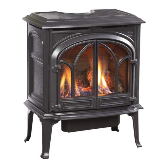
Jøtul GF 300 DV II Allagash Installation And Operation Instructions Manual
Direct vent gas stove
Hide thumbs
Also See for GF 300 DV II Allagash:
- Installation and operation instructions manual (32 pages) ,
- Installation and operation instructions manual (40 pages) ,
- Instructions (4 pages)
Table of Contents
Advertisement
WARNING: If the information in these
instructions is not followed exactly, a fire
or explosion may result causing property
damage, personal injury or loss of life.
– Do not store or use gasoline or other
flammable vapors and liquids in the vicinity
of this or any other appliance.
– WHAT TO DO IF YOU SMELL GAS
• Do not try to light any appliance.
• Do not touch any electrical switch; do not
use any phone in your building.
• Immediately call your gas supplier from a
neighbor's phone. Follow the gas supplier's
instructions.
• If you cannot reach your gas supplier, call
the fire department.
– Installation and service must be performed
by a qualified installer, service agency or the
gas supplier.
– In the Commonwealth of Massachusetts,
a carbon monoxide (CO) detector shall be
installed in the same room as the appliance.
This appliance may be installed in an aftermarket,
permanently located, manufactured home or mobile
home, where not prohibited by local codes.
This appliance is only for use with the types of gas
indicated on the rating plate. A conversion kit is
supplied with the appliance.
INSTALLER: Leave this manual with the appliance.
CONSUMER: Retain this manual for future reference.
Installation and
Operation Instructions
ATTENTION : CES INSTRUCTIONS DOIVENT
DEMUERER AVEC LE PROPRIÉTERE D'UNE
MAISON.
AVERTISSEMENT: Assurez-vous de bien
suivreles instructions données dans cette
notice pour réduire auninimum le risque
d'incendie ou d'explosion ou pour éviter
tout dommage matériel, toute blessure ou la
mort.
– Ne pas entreposer ni utiliser d'essence ni
d'autres vapeurs ou liquides inflammables
dans le voisinage de cet appareil ou de tout
autre appareil.
– QUE FAIRE SI VOUS SENTEZ UNE ODEUR DE GAZ:
• Ne pas tenter d'allumer l'appareil.
• Ne touchez à aucum interrupteur.
Ne pas vous servir des téléphones se
trouvant dans le bâtiment où vous
trouvez.
• Appelez immédiatement votre
fournisseur de gaz depuis un voisin.
Suivez les instructions du fournisseur.
• Si vou ne pouvez rejoindre le
fournisseur de gaz, appelez le service des
incendies.
– L'installatione l'entretien doivent être
assurés par un installateur ou un service
d'entretien qualifié ou par le fournisseur
de gaz.
137775_Rev_K 7.29.10
1
Advertisement
Table of Contents

Related Manuals for Jøtul GF 300 DV II Allagash


Summary of Contents for Jøtul GF 300 DV II Allagash
-
Page 1: Operation Instructions
137775_Rev_K 7.29.10 Installation and Operation Instructions WARNING: If the information in these ATTENTION : CES INSTRUCTIONS DOIVENT instructions is not followed exactly, a fire DEMUERER AVEC LE PROPRIÉTERE D’UNE or explosion may result causing property MAISON. damage, personal injury or loss of life. AVERTISSEMENT: Assurez-vous de bien suivreles instructions données dans cette –... -
Page 2: Service Tools
• Torx T-20 screwdriver to attach your purchase receipt to this page for future • Tin snips reference. MODEL NAME: Jøtul GF 300 DV II Allagash Gas Stove We recommend that SERIAL NUMBER:_______________________________ our gas products be installed and serviced by... -
Page 3: Table Of Contents
137775_Rev_K 7.29.10 Table of Contents Service Tools ..........2 Specifications ..........4 Jøtul GF 300 DV II Allagash General Information ........ 5 Safety Information ........6 Direct Vent Gas Heater Installation Requirements Location ..........6 Manufactured and Distributed by: Hearth Protection .......6 Jøtul North America 55 Hutcherson Dr. -
Page 4: Specifications
137775_Rev_K 7.29.10 GF 300 DV Specifications Specifications 27 1/2” 698 mm Input Rates Natural Gas 26,000 BTU/hr. maximum input 14,000 BTU/hr. minimum input Propane 22 1/4” 26,000 BTU/hr. maximum input 565 mm 14,000 BTU/hr. minimum input Inlet Pressure: Natural Gas: 5.0 WC (1.24 kPa) 7.0 WC (1.74 kPa) Propane:... -
Page 5: General Information
137775_Rev_K 7.29.10 General Information THIS HEATER MUST BE INSTALLED AND MAINTAINED BY A QUALIFIED SERVICE AGENCY. Glass Panel The installation and repair of this appliance must be Do not operate this appliance with the glass done by a qualified service person. Failure to properly front removed, cracked, or broken. -
Page 6: Safety Information
137775_Rev_K 7.29.10 Safety Information Location Due to the high operating temperatures this In selecting a location for the stove, consider the appliance should be located out of traffic and following points: away from furniture, draperies, etc. Maintain 1) Heat distribution 2) Vent termination requirements proper clearance to combustible mantels and 3) Gas supply line routing... -
Page 7: Clearances
137775_Rev_K 7.29.10 Stove and Vent Clearance Requirements Minimum Clearances from the Stove to Combustibles: See figs. 2-4. 2” (51 mm) Rear: 2” (51 mm) To Rear Wall Ceiling: 35 1/4” (870 mm) Corner: 2” (51 mm) Sides: 3” (76 mm) 3”... -
Page 8: Vent Requirements
137775_Rev_K 7.29.10 Venting Requirements Vent Restriction The GF 300 DV II is equipped with an Exhaust Restrictor The Jøtul GF 300 DV II gas stove may be installed with a vertical or horizontal termination and must conform to Plate which enables you to regulate the flow of exhaust the configuration requirements described below. -
Page 9: Vertical Termination
137775_Rev_K 7.29.10 Figure 6. Exhaust restrictor positions - viewed from front See Fig. 6 with top plate removed. Detail Vertical Vent Termination The Jøtul GF 300 DV II can be vertically vented through a ceiling or to a roof termination with the following guide- lines: The termination should fall within the shaded areas ... - Page 10 137775_Rev_K 7.29.10 Vent Windows for Natural Gas COLINEAR VENT 35 Ft. (10.67 m) 35 Ft. 35 Ft. COAXIAL VENT (10.67 m) (10.67 m) 30 Ft. (9.14 m) Up to four 45° or two 90° elbows 25 Ft. permitted in (7.62 m) addition to the 25 Ft.
- Page 11 137775_Rev_K 7.29.10 Vent Windows for Propane COLINEAR VENT 35 Ft. (10.67 m) 35 Ft. (10.67 m) COAXIAL VENT 30 Ft. (9.14 m) Up to four 45° or two 90° elbows permitted in 25 Ft. (7.62 m) addition to the 25 Ft. starter elbow.
-
Page 12: Co-Linear Termination
137775_Rev_K 7.29.10 #991 High Wind Cap Exhaust Gas Intake Air Co-linear Vent Installation Max. Co-linear The GF 300 DVII may be vented through a masonry or Height - 35 ft. (10.66 m) Class A prefabricated chimney using a Co-linear Flexible Min. -
Page 13: Coaxial Chimney Conversion
137775_Rev_K 7.29.10 Masonry or Prefabricated Chimney #991 Vertical Termi- Exhaust nation Cap Conversion Cap Adaptor- The GF 300 DV II is approved for use with Simpson Dura- included in Intake Air #934 Kit vent Chimney Kit #934 in a masonry chimney or a prefab- ricated solid fuel listed chimney. -
Page 14: Horizontal Termination
137775_Rev_K 7.29.10 12” Horizontal Termination Any horizontal termination must fall within the shaded portion of the vent window graph illustrated in figs. 9 or 11. For Snorkel Terminations, see below. Any horizontal termination except a snorkel termina- 24” tion, must include: 14”... -
Page 15: Vent Terminal Clearances
137775_Rev_K 7.29.10 Horizontal Termination Clearance Figure 20. Vent Terminal Clearances - ANSI Z21.88-2002, CSA 2.33-2002, and National Fuel Gas Code. A = Clearance above grade, veranda, porch , deck, or balcony Clearance above paved sidewalk or a paved driveway located : 12 inches (30 cm) minimum. -
Page 16: Mobile Home Installation
137775_Rev_K 7.29.10 Mobile Home Installation WARNING: The GF 300 DV II can be installed for use in a mobile home THE CONVERSION KIT IS TO BE INSTALLED BY in the U.S. and Canada provided: AN AUTHORIZED JØTUL SERVICE TECHNICIAN IN ACCORDANCE WITH THE MANUFACTURER’S 1. - Page 17 137775_Rev_K 7.29.10 Fuel Conversion Procedure Air Shutter 1. Turn off gas supply to stove. 2. Remove the stove Top Plate. 3. Disengage the two Glass Frame Latches at the top of the firebox. See illustration on page 5. Carefully lift the glass panel up and out of the stove.
-
Page 18: Gas Connection
137775_Rev_K 7.29.10 Main Gas Valve 15. Install the new regulator: Be sure the new gasket is Apply small label. properly positioned and tighten screws securely. 16. Install the identification labels to the stove so that they can be seen by any person who may be servicing the stove. -
Page 19: Gas Pressure
137775_Rev_K 7.29.10 3/8” NPT x 3/8” Flare Fitting 1/2” x 3/8” Flare Shut-off Valve 3/8” Flex Tubing 3/8”Nipple Figure 29. Pressure test points. 3/8” Union Gas Stub 3/8” Close Nipple 3/8” Shut-off Valve 1/2” x 3/8” Reducer INLET GAS PRESSURES Figure 28. -
Page 20: Air Shutter Adjustment
137775_Rev_K 7.29.10 Optional Wall Thermostat or Flame Appearance / Air Shutter Remote Control Adjustment Use only a 750 millivolt DC two-wire circuit thermostat The GF 300 DV gas stove is shipped from the factory with this appliance. The thermostat should be placed equipped to burn Natural gas. -
Page 21: Log Set Installation
137775_Rev_K 7.29.10 Log Set Installation PN 220729 Brick Kit Note: Install the optional Antique Brick Kit 155370 before installing the logset. See page 27 and the instructions provided with that kit. The GF 300 DV logset must be installed before operating the burner. -
Page 22: System Check
137775_Rev_K 7.29.10 System Check 1” (25mm) 3/8” 1/8” (8mm) 1. PURGING THE GAS LINE: When lighting the appliance (3mm) Min. for the first time, it will take a few moments to clear Min. the gas line of air. Once this purge is complete, the appliance will operate as described in the lighting instructions. -
Page 23: Operation
137775_Rev_K 7.29.10 Operation Familiarize yourself with the controls of the GF 300 DV. Make sure that anyone else using the appliance is also familiar with the controls and operation procedures. Always follow the Lighting Instructions on the inside back cover of this manual and also located on the Rating Plate attached to the rear shroud. -
Page 24: Maintenance
137775_Rev_K 7.29.10 Maintenance FOR REPLACEMENT, USE ONLY JØTUL CERAMIC GLASS PANEL 220576. DO NOT USE ANY OTHER TYPE OF Your Jøtul GF 300 DV Allagash and its venting system GLASS WITH THIS APPLIANCE. should be inspected before use and at least annually by a qualified service technician. -
Page 25: Optional Blower Installation
137775_Rev_K 7.29.10 Optional Blower # 156000 Read these instructions before beginning the installa- tion. 1. Unpack and check the contents of the blower kit. The kit includes two Air Deflectors and two #7 x 1/2” screws that will not be used with the GF 300 DV Allagash stove. -
Page 26: Blower Operation
137775_Rev_K 7.29.10 Figure 44. Attach Blower to the Mounting Bracket with the wingscrew and connect wires to Snapstat and female control quick connect. Male Snapstat Connectors Female Quickconnector Wingscrew Blower Operation The optional variable-speed blower will enhance heat circulation around the firebox and out into the room. The blower is controlled by a heat activated switch (snap- Blower Wiring Diagram stat) that will ONLY function when the control switch... -
Page 27: Optional Brick Kit Installation
137775_Rev_K 7.29.10 Optional Antique Brick Kit # 155648 CAUTION! THE BRICK PANELS AND LOG PARTS ARE EXTREMELY FRAG- ILE. HANDLE WITH CARE. Figure 48. Disengage the compression latches Read these instructions before beginning the installa- to remove the glass tion. frame. -
Page 28: Illustrated Parts Breakdown
137775_Rev_K 7.29.10 GF 300 DV II Illustrated NOTE: THE GAS CONTROL VALVE ASSEMBLY Parts Breakdown IS MOUNTED AT THE CENTER FRONT OF ALL STOVES BEGINNING WITH SERIAL NO. 30000. Figure 52. Illustrated Parts Breakdown - GF 300 DV II Allagash... -
Page 29: Replacement Parts List
137775_Rev_K 7.29.10 GF 300 DV II Allagash Parts List Blue Black Ivoryu FJøtul Iron Brown Blue Cast Iron Parts Matte Black Jøtul Iron Enamel Enamel Enamel Majolica Majolica Enamel Enamel Side Plate 10203292 10203285 102033 10203229 10203246 10203247 10203248 Base Plate... -
Page 30: Warranty Statement
137775_Rev_K 7.29.10 Jøtul Gas Product Limited Warranty 3) Damage due to service performed by an installer, service agency or gas This warranty policy applies to gas products identified supplier, unless otherwise agreed to in writing by JØTUL. by Jøtul, Scan, and Atra trade names, as set forth below. 4) Labor or other costs associated with the repair of gas controls, A. -
Page 31: Lighting Instructions
137775_Rev_K 7.29.10 LIGHTING INSTRUCTIONS FOR YOUR SAFETY, READ BEFORE LIGHTING. WARNING: IF YOU DO NOT FOLLOW THESE INSTRUCTIONS EXACTLY, A FIRE OR EXPLOSION MAY RESULT CAUS- ING PROPERTY DAMAGE, PERSONAL INJURY, OR LOSS OF LIFE. • If your gas supplier cannot be reached, call the A. -
Page 32: Gorham, Maine
137775_Rev_K 7.29.10 This appliance must be installed in conformance with local and national building regulations. Before beginning the installation, it is important that the these instructions be carefully read and understood. Jøtul maintains a policy of continual product development. Consequently, products may differ in speci- fication, color or type of accessories from those illustrated or described in various publications.
Need help?
Do you have a question about the GF 300 DV II Allagash and is the answer not in the manual?
Questions and answers