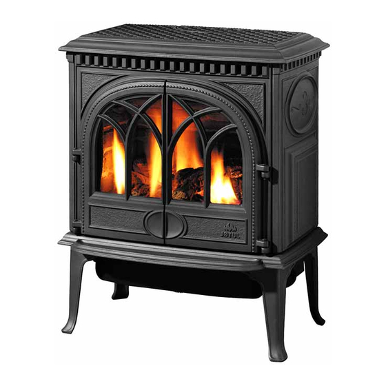
Jøtul GF 300 BV Allagash Installation And Operation Instructions Manual
Direct vent gas stove
Hide thumbs
Also See for GF 300 BV Allagash:
- Installation and operation instructions manual (28 pages) ,
- Installation and operation instructions manual (28 pages)
Table of Contents
Advertisement
Quick Links
CAUTION: THESE INSTRUCTIONS MUST
REMAIN WITH THE HOMEOWNER.
WARNING: If the information in these
instructions is not followed exactly, a fire
or explosion may result causing property
damage, personal injury or loss of life.
– Do not store or use gasoline or other
flammable vapors and liquids in the
vicinity of this or any other appliance.
– WHAT TO DO IF YOU SMELL GAS
• Do not try to light any appliance.
• Do not touch any electrical switch; do
not use any phone in your building.
• Immediately call you gas supplier from a
neighbor's phone. Follow the gas
supplier's instruction.
• If you cannot reach your gas supplier,
call the fire department.
– Installation and service must be
performed by a qualfied installer, service
agency or the gas supplier.
– In the Commonwealth of Massachusetts, a
carbon monoxide (CO) detector shall be
installed in the same room as the
appliance.
Installation and
Operation Instructions
ATTENTION : CES INSTRUCTIONS DOIVENT
DEMUERER AVEC LE PROPRIÉTERE D'UNE
MAISON.
AVERTISSEMENT: Assurez-vous de bien
suivreles instructions données dans cette
notice pour réduire auninimum le risque
d'incendie ou d'explosion ou pour éviter tout
dommage matériel, toute blessure ou la mort.
– Ne pas entreposer ni utiliser d'essence ni
d'autres vapeurs ou liquides inflammables
dans le voisinage de cet appareil ou de tout
autre appareil.
– QUE FAIRE SI VOUS SENTEZ UNE ODEUR DE
GAZ:
• Ne pas tenter d'allumer l'appareil.
• Ne touchez à aucum interrupteur. Ne pas
vous servir des téléphones se trouvant
dans le bâtiment où vous trouvez.
• Appelez immédiatement votre
fournisseur de gaz depuis un voisin. Suivez
les instructions du fournisseur.
• Si vou ne pouvez rejoindre le fournisseur
de gaz, appelez le service des incendies.
– L'installatione l'entretien doivent être
assurés par un installateur ou un service
d'entretien qualifié ou par le fournisseur
de gaz.
1
Advertisement
Table of Contents

Related Manuals for Jøtul GF 300 BV Allagash


Summary of Contents for Jøtul GF 300 BV Allagash
-
Page 1: Operation Instructions
Installation and Operation Instructions ATTENTION : CES INSTRUCTIONS DOIVENT CAUTION: THESE INSTRUCTIONS MUST DEMUERER AVEC LE PROPRIÉTERE D’UNE REMAIN WITH THE HOMEOWNER. MAISON. AVERTISSEMENT: Assurez-vous de bien WARNING: If the information in these suivreles instructions données dans cette instructions is not followed exactly, a fire notice pour réduire auninimum le risque or explosion may result causing property d’incendie ou d’explosion ou pour éviter tout... -
Page 3: Table Of Contents
Table of Contents Jøtul GF BV Allagash Service Tools ..........4 Direct Vent Gas Heater Specifications ........... 4 General Information ....... 5 Manufactured and Distributed by: Jøtul AS Safety Information ........6 Fredrikstad, Norway Installation Requirements Jøtul North America 55 Hutcherson Dr. Location .......... -
Page 4: Service Tools
GF 300 BV Allagash Specifications The Jøtul GF 300 BV Allagash is a atmospherically- vented gas fireplace heater designed only for vertical THIS FIREPLACE IS SHIPPED FROM THE FACTORY venting directly to the outside of the house, using FOR USE WITH NATURAL GAS ONLY. FOR USE WITH listed, Type B-vent pipe. -
Page 5: General Information
Consult the local or national installation code(s) to General Information assure that adequate combustion and ventilation air is available. THIS HEATER MUST BE INSTALLED AND MAINTAINED Installer l’appareil selon les codes ou reglements BY A QUALIFIED SERVICE AGENCY. locaux, ou, en l’absence de tels reglements, selon les Codes d’installation CAN/CGA-B149. -
Page 6: Safety Information
Safety Information Location During normal operation, the GF 300 BV gas stove will In selecting a location for the stove, consider the reach high surface temperatures. Therefore: following points: 1) Heat distribution 2) Vent termination requirements Due to the high operating temperatures, this appli- 3) Gas supply line routing ance should be located out of traffic areas and away 4) Traffic areas, furniture, draperies, etc. -
Page 7: Clearances
Stove and Vent Clearance Requirements Minimum Clearances from the Stove to Combustibles See figs. 2-3. 2” (51 mm) Rear: 2” (51 mm) - measured from Draft Hood To Rear Wall Ceiling: 32 1/4” (819 mm) - measured from stove top Corner: 3”... - Page 8 Vent Requirements The GF 300 BV Allagash is specifically designed to Min. operate using 4” Type B vent pipe components or a Listed Height Flexible gas liner. Roof Pitch in Ft. • All venting components must be installed in accor-...
- Page 9 Venting through a Masonry or Prefabricated Manufactured Chimney • When 6” diameter decorative pipe is installed to cover the venting any Listed Flexible Gas liner must Listed be connected directly to the stove’s draft hood. Storm collar termination • Use of single wall connector pipe as a vent is required cap required Top sealing...
-
Page 10: Vent Requirements
Approved B-Vent Configurations Listed B-Vent Termination Listed B-Vent Cap required. Termination Cap required. Maximum total NOTE: horizontal Maximum Installation at anywhere in chimney altitude greater NOTE: venting height off than 2000’ Installation at configuration Draft Hood is requires Minimum chimney altitude greater is 4 feet. -
Page 11: Fuel Conversion
Fuel Conversion Conversion Kit Contents: • 1, regulator tower labeled for propane • 3, regulator tower screws The GF 300 BV gas stove is shipped from the factory • 1, burner orifice (#39 for NG, #53 for LPG) equipped to burn NATURAL GAS only. If PROPANE gas is •... - Page 12 Lift out the Burner Plate: NOTE: There are no screws securing the Burner to the floor of the firebox. Pull the Air Shutter Air Shutter forward and lift the burner together with shutter up and out of the stove as a unit. See fig. 13. Change the Burner Orifice.
-
Page 13: Gas Supply Connection
Pilot Head Regulator Tower Thermopile Orifice Ignitor Remove black gasket from regulator assembly Retainer Thermocouple Clip Valve Pilot Base Figure 16. Pilot orifice removal and replacement. Figure 17 Regulator assembly. 15. Install the new regulator: Be sure the new gasket is Gas Supply Connection properly positioned and tighten screws securely. -
Page 14: Gas Pressure
3/8” NPT x 3/8” Flare Fitting 1/2” x 3/8” Flare Shut-off Valve 3/8” Flex Tubing 3/8”Nipple Figure 19. Pressure test points. 3/8” Union Gas Stub 3/8” Close Nipple 3/8” Shut-off INLET GAS PRESSURES Valve 1/2” x 3/8” (inches water column) Reducer Figure 18. -
Page 15: Log Set Installation
PN 220729 Log Set Installation Brick Kit Note: Install the optional Antique Brick Kit 155370 before installing the logset. See page 22 and the instructions provided with that kit. The GF 300 BV logset must be installed before operating the burner. The logset includes four log pieces, packaged inside the firebox, and a quantity of ember stones packaged in the Miscellaneous Parts bag. -
Page 16: Flame Adjustment
Flame Appearance / Air Shutter Optional Wall Thermostat or Adjustment Remote Control The GF 300 BV gas stove is shipped from the factory Use only a 750 millivolt DC two-wire circuit thermostat equipped to burn Natural gas. If the stove has been with this appliance. -
Page 17: Decorative Pipe
The use of decorative pipe is optional. No decorative ance for the first time, it will take a few moments to pipe is included with the Jøtul GF 300 BV Allagash, clear the gas line of air. Once this purge is complete,... -
Page 18: Operation
WARNING: If a vacuum is used during any service on the stove, AIR SHUTTER ADJUSTMENTS SHOULD ONLY BE ALWAYS be sure the stove is cold and there are NO hot PERFORMED BY A QUALIFIED PROFESSIONAL SERVICE embers. TECHNICIAN. 5. Remember, this appliance has a continuous burning pilot flame. -
Page 19: Maintenance
Maintenance Your Jøtul GF 300 BV Allagash and its venting system FOR REPLACEMENT, USE ONLY JØTUL CERAMIC GLASS should be inspected before use and at least annually by REPLACEMENT KIT 155599. DO NOT USE ANY OTHER a qualified service technician. -
Page 20: Optional Blower
Optional Blower # 155620 CONNECT THE GAS SUPPLY TO THE STOVE BEFORE INSTALLING THIS BLOWER. IF NECESSARY, USE A 90° ELBOW OFF THE GAS VALVE TO CREATE ADEQUATE GAS LINE CLEARANCE. BE SURE ALL WIRE CONNECTIONS HAVE BEEN MADE BEFORE CONNECTING TO POWER SUPPLY. -
Page 21: Blower Operation
Figure 35. Attach Blower to the stove bottom and connect wires to Snapstat Male and female control quick Quickconnector connect. Snapstat Connectors Female Quickconnector M6 x 20 mm Hex Bolts Blower Operation BLOWER The optional variable-speed blower will enhance heat circulation around the firebox and out into the room. -
Page 22: Optional Antique Brick Kit
Optional Antique Brick Kit # 155648 CAUTION! Figure 39. THE BRICK PANELS AND LOG PARTS ARE EX- Disengage the TREMELY FRAGILE. HANDLE WITH CARE. compression latches to remove the glass Read these instructions before beginning the installa- frame. tion. 1. Remove the Top Plate. Simply lift it up off of the stove body. -
Page 23: High Altitude Adjustment
High Altitude Adjustment Installations burning natural gas and located at altitudes from 2000 - 4500 ft. (610 M - 1370 M), require compensa- tion for the thinner air (less volume of air per cubic foot). Replace with #40 Higher altitudes affect the atmospheric pressure and orifice heat value of gaseous fuels. -
Page 25: Replacement Parts List
GF 300 BV Allagash Parts List Blue Black Blue Black Blue Black Blue Black Blue Black Iv Iv Iv Iv Ivor or or or ory y y y y Jøtul Ir Jøtul Ir Jøtul Ir Jøtul Ir Jøtul Iron Br Br Br Br Bro o o o o wn... - Page 26 Record the following information to help your dealer determine what you will need for parts and service. GF 300 BV Allagash M M M M M ODEL NA ODEL NA ODEL NA ODEL NA ODEL NAME: ME: _________________________ SERIAL NUMBER: ________________________...
-
Page 27: Lighting Instructions
LIGHTING INSTRUCTIONS FOR YOUR SAFETY, READ BEFORE LIGHTING. WARNING: IF YOU DO NOT FOLLOW THESE INSTRUCTIONS EXACTLY, A FIRE OR EXPLOSION MAY RESULT CAUSING PROPERTY DAMAGE, PERSONAL INJURY, OR LOSS OF LIFE. A. A. A. A. A. This appliance has a pilot which must be lit •... - Page 28 This appliance must be installed in conformance with local and national building regulations. Before beginning the installation, it is important that the these instructions be carefully read and understood. Jøtul maintains a policy of continual product development. Consequently, products may differ in specification, color or type of accessories from those illustrated or described in various publications.
Need help?
Do you have a question about the GF 300 BV Allagash and is the answer not in the manual?
Questions and answers