Table of Contents
Advertisement
Quick Links
AV Receiver
DTR-6.3/5.3
Instruction Manual
Thank you for purchasing the
Please read this manual thoroughly before making
connections and plugging in the unit. Following the
instructions in this manual will enable you to obtain
optimum performance and listening enjoyment
from your new AV Receiver. Please retain this
manual for future reference.
AV Receiver.
Contents
Appendix
2
8
37
62
75
Advertisement
Table of Contents

Related Manuals for Integra DTR-5.3


Summary of Contents for Integra DTR-5.3
- Page 1 AV Receiver DTR-6.3/5.3 Instruction Manual Thank you for purchasing the Please read this manual thoroughly before making connections and plugging in the unit. Following the instructions in this manual will enable you to obtain optimum performance and listening enjoyment from your new AV Receiver. Please retain this manual for future reference.
-
Page 2: Before Using Important Safeguards
WARNING: TO REDUCE THE RISK OF FIRE OR ELECTRIC SHOCK, DO NOT EXPOSE THIS APPLIANCE TO RAIN OR MOISTURE. CAUTION: TO REDUCE THE RISK OF ELECTRIC SHOCK, DO NOT REMOVE COVER (OR BACK). NO USER-SERVICEABLE PARTS INSIDE. REFER SERVICING TO QUALIFIED SERVICE PERSONNEL. -
Page 3: Precautions
2. AC Fuse The fuse is located inside the chassis and is not user-serviceable. If power does not come on, contact your Integra/Onkyo authorized service station. 3. Care From time to time you should wipe the front and rear panels and the cabinet with a soft cloth. -
Page 4: Table Of Contents
When using the ZONE 2 SPEAKERS terminals ... 22 When using the ZONE 2 PRE OUT terminals ... 22 When using the ZONE 2 OUT terminals ... 22 Connections (DTR-5.3) ... 23 Connecting your audio components ... 23 Connecting your video components ... 24 AC OUTLETS ... - Page 5 Selecting an Audio Component ... 43 Basic operation (DTR-6.3) ... 43 Basic operation (DTR-5.3) ... 44 Selecting speakers (Speakers A, B) (DTR-5.3 only) ... 44 Selecting the type of audio input signal ... 45 Temporarily changing the speaker output levels ... 45 To change the display of the input source from TAPE to MD ...
-
Page 6: Features
I IR input/output terminals I Powerful backlit/preprogrammed learning remote with macro and mode-key LEDs DTR-5.3 Amplifier Features I 80 W × 2 (Front)/ 80 W (Center)/ 80 W × 2 (Surround)/ 80 W (Surround Back) at 8 ohms, 20 Hz - 20 kHz, 0.08 % THD (FTC rated) -
Page 7: Supplied Accessories
Supplied accessories Check that the following accessories are supplied with the DTR-6.3/5.3. AM loop antenna × 1 Remote controller (RC-481M) × 1 Batteries (AA, R6 or UM-3) × 2 Before using this unit Installing the remote controller batteries 1. Remove the battery compartment cover by pressing it and sliding it in the direction shown by the arrow below. -
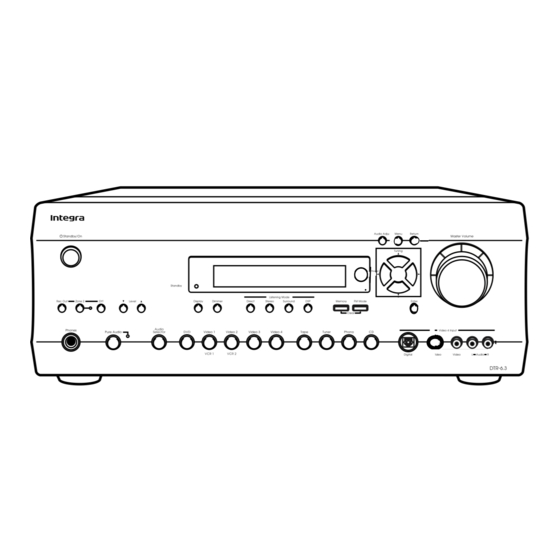
Page 8: Front Panel Facilities
Front panel facilities Here is an explanation of the controls and displays on the front panel of the DTR-6.3/5.3. Front panel <DTR-6.3> <DTR-5.3>... - Page 9 Press to display the screen for the item that is selected in the Setup Menu. Master Volume dial [43, 44] DTR-5.3: Use to control the volume. DTR-6.3: Use to control the volume in the main zone. The volume for the remote zone (Zone 2) is independent.
- Page 10 When Rec Out is selected, nothing is output to Zone 2. When Zone 2 is selected, Rec Out is automatically fixed to SOURCE. Speakers A/B buttons (DTR-5.3 only) [44] Press these buttons to turn on and off speakers systems A and B.
-
Page 11: Front Panel Display
ZONE 2 indicator (DTR-6.3 only) Lights when using the remote zone (Zone 2). REC OUT indicator (DTR-6.3 only) Lights when recording the input source from one component to another (Rec Out). Speakers A/B indicators (DTR-5.3 only) Indicates which speaker system is currently in use. -
Page 12: Remote Controller
Press the Angle button to select a camera angle when playing a DVD-Video with multiple angle playback. Press the Subtitle button to select a subtitle language when playing a DVD-Video. [64] CD/TAPE/DVD/MD operation buttons [62–65] Press to operate other Integra/Onkyo components connected to the DTR-6.3/5.3 using the terminals. - Page 13 DTR-6.3: When in the RCVR mode, press to perform operations on the remote zone (Zone 2). [59] DTR-5.3: Switches the audio signal output to the A-BUS keypad. [28] When in the MD mode, press to enter the selected song (Enter). [65]...
-
Page 14: Connections
Connections • Be sure to always refer to the instructions that came with the component that you are connecting. • Do not plug in the power cord until all connections have been properly made. • For input jacks, red connectors (marked R) are used for the right channel, white connectors (marked L) are used for the left channel, and yellow connectors (marked V) are used for video connection. - Page 15 VIDEO 2 12V TRIGGER OUT [28] Connecting your audio components [16] Connecting a Connecting your video subwoofer [32] components [17] DTR-5.3 Connecting antennas [35] 12V TRIGGER OUT [28] A-BUS [28] FM 75 ANTENNA 12 V TRIGGER IR OUT IR OUT...
-
Page 16: Connections (Dtr-6.3)
Connections Here is an explanation of typical ways to connect various components to the DTR-6.3. There are many ways that any one component can be connected, and it is up to you to decide which method best fits your situation. The directions given here are only one option and should only be thought of as such. -
Page 17: Connecting Your Video Components
Connections (DTR-6.3) Connecting a DVD Player with 5.1-Channel Output FM 75 ANTENNA 12 V TRIGGER IR OUT ZONE 2 ZONE 2 DIGITAL INPUT DIGITAL COAXIAL OUTPUT OPTICAL OPTICAL COAXIAL DIGITAL INPUT SUBWOOFER PRE OUT TAPE : Signal flow Connecting your video components Below is an example of how you can connect your video components to the DTR-6.3. -
Page 18: Connections (Dtr-6.3)
Connections (DTR-6.3) Connecting a DVD Player with 2-Channel (L/R) Audio Output FM 75 ANTENNA 12 V TRIGGER IR OUT ZONE 2 DIGITAL INPUT DIGITAL OUTPUT OPTICAL OPTICAL SUBWOOFER PRE OUT : Signal flow 4. Connecting a DVD player (DVD) Using an RCA video cable, connect the video output jack (composite) of the DVD player to the DVD VIDEO IN jack of the DTR-6.3. - Page 19 Connections (DTR-6.3) : Signal flow 6. Satellite tuner or television (VIDEO 3) Digital audio output (optical) Video output S Video output L (white) Analog audio output R (red) 5. Connecting a video cassette recorder (VIDEO 1) Using RCA video cables, connect the video output jack (composite) of the video cassette recorder to the VIDEO 1 VIDEO IN jack of the DTR-6.3 and connect the video input jack of the video cassette recorder to the VIDEO 1 VIDEO OUT jack of the DTR-6.3.
- Page 20 Connections (DTR-6.3) Video output S Video output Video input S Video input 7. DVD recorder, other digital video recording device (VIDEO 2) L (white) Analog audio input R (red) L (white) Analog audio output R (red) 7. Connecting a DVD recorder or other digital video recording device (VIDEO 2) Using RCA video cables, connect the video output jack (composite) of the device to the VIDEO 2 VIDEO IN jack of the DTR-6.3 and...
-
Page 21: Pre Out
Connections (DTR-6.3) 9. Connecting video camera, etc. (Video 4 Input) Using an RCA video cable, connect the video output jack (composite) of the device to the Video 4 Video jack of the DTR-6.3. Or if the device has an S video output jack, connect it to the Video 4 S Video jack of the DTR-6.3 using an S video cable. -
Page 22: Connecting The Remote Zone (Zone 2) Speakers
Connecting the remote zone (Zone 2) speakers (DTR-6.3 only) The DTR-6.3 allows you to listen to two separate input sources at the same time. This allows you to, for example, place speakers in two different rooms so that two or more people can enjoy two different kinds of music at the same time. -
Page 23: Connections (Dtr-5.3)
(DTR-5.3) Here is an explanation of typical ways to connect various components to the DTR-5.3. There are many ways that any one component can be connected, and it is up to you to decide which method best fits your situation. The directions given here are only one option and should only be thought of as such. -
Page 24: Connecting Your Video Components
: Signal flow Connecting your video components Below is an example of how you can connect your video components to the DTR-5.3. Refer to the diagram above for the following connection examples. COMPONENT VIDEO INPUT/OUTPUT For DVD players or other devices that have component video connectors, the DTR-5.3 has two banks of component video input... - Page 25 Using an RCA video cable, connect the video output jack (composite) of the DVD player to the DVD VIDEO IN jack of the DTR-5.3. Or if the DVD player has an S video output jack, connect it to the DVD S VIDEO IN jack with an S video cable.
- Page 26 DTR-5.3. Or if the device has an S video output jack, connect it to the VIDEO 2 (or 3) S VIDEO IN jack of the DTR-5.3 using an S video cable. Or if the device has component video outputs, connect them to the COMPONENT VIDEO INPUT 1 or 2 jacks on the DTR- 5.3.
- Page 27 7. Connecting video camera, etc. (Video 4 Input) Using an RCA video cable, connect the video output jack (composite) of the device to the Video 4 Video jack of the DTR-5.3. Or if the device has an S video output jack, connect it to the Video 4 S Video jack of the DTR-5.3 using an S video cable.
-
Page 28: Ac Outlets
CD player or other source component, or the line-out terminal of another amplifier. By using the Zone2 button on the remote controller of the DTR-5.3, you can change which audio signal is output to the A-BUS keypad: either the signal selected by the input selectors on the DTR-5.3, or the audio signal input at the A-BUS Line In terminal. -
Page 29: Remote Control
DTR-6.3/5.3. The other one can be used to daisy chain with another component. • With Integra/Onkyo DVD players, you can enter the pre- program code so that you can operate the DVD player directly with the remote controller without connecting the (see page 66). -
Page 30: Operating Components Not Reached By The Remote Controller Signals (Ir In)
Operating components not reached by the remote controller signals (IR IN) In order to use the remote controller to control the DTR-6.3/5.3 from a remote location, you will need to prepare a multi-room kit (sold separately) such as one of those given below: •... -
Page 31: Connecting Speakers
Connecting speakers Before connecting the speakers, it is very important to place them properly for the optimum sound space for your listening pleasure. Be sure to refer to the instruction manuals that came with the speakers during placement and connection. Furthermore, be aware that for surround playback, the configuration and placement of your speakers are both very important. -
Page 32: Connecting Speakers
SUBWOOFER PRE OUT jack and the subwoofer to the amplifier. Connecting to the SPEAKERS B terminals (DTR-5.3 only) If you require an additional set of front speakers (left and right), such as for use in another room, connect them to the FRONT SPEAKERS B inputs. - Page 33 OUTPUT OPTICAL OPTICAL COAXIAL DIGITAL INPUT FRONT SUBWOOFER PRE OUT TAPE VIDEO 3 VIDEO 2 VIDEO 1 Subwoofer DTR-5.3 Front right A speaker FM 75 ANTENNA COMPONENT VIDEO INPUT 2 INPUT 1 RS232 12 V TRIGGER IR OUT LINE IN...
-
Page 34: Connecting The Power
Connecting the power Diagram for DTR-6.3 Standby/On • Before you plug in the DTR-6.3/5.3, confirm that all connections have been made properly. • Turning on the power may cause a momentary power surge, which might interfere with other electrical equipment on the same circuit, such as computers. -
Page 35: Connecting Antennas
Connecting antennas To use the tuner of the DTR-6.3/5.3, it is necessary to prepare the supplied FM and AM antennas. • Adjustment and placement of the FM and AM antennas for better reception must be done while listening to a station broadcast. -
Page 36: Connecting An Fm Outdoor Antenna
Connecting antennas Connecting an FM outdoor antenna Make sure to follow the general rules given below: • Keep the antenna away from noise sources (neon signs, busy roads, etc.). • It is dangerous to put the antenna close to power lines. Keep it well away from power lines, transformers, etc. -
Page 37: Configuring The Speakers
Configuring the speakers Menu To create the optimum sound space for both visual and audio pleasure, it is necessary to set the size of the speakers and their distance from your normal listening position. Once made, you will not need to change these settings unless you change the speaker configuration or positions. - Page 38 Configuring the speakers 4. Use the cursor buttons to select “Subwoofer” and then use the cursor buttons to select the subwoofer setting. Yes: Select when a subwoofer is connected. No: Select when a subwoofer is not connected. DTR-6.3/5.3 5. Use the cursor buttons to select “Front”...
-
Page 39: Setting The Speaker Distance From Your Normal Listening Position
Configuring the speakers Setting the speaker distance from your normal listening position Each speaker can be set between 1 and 30 feet (0.3 and 9 meters) in 1-foot (0.3 meter) increments. Select the setting closest to the actual distance from the speaker to your normal listening position. Note: Speakers that you selected “No”... -
Page 40: Buttons Used For Navigating Through The Menus
Configuring the speakers (1) Remember the volume level of this noise and then press the cursor button. The DTR-6.3/5.3 will now emit the pink noise from the center speaker. (2) Using the cursor buttons, adjust the volume level of the noise from the center speaker so that it is at the same level as that that was emitted from the front left speaker. -
Page 41: Listening To Radio Broadcasts
Listening to Radio Broadcasts One of the features of the DTR-6.3/5.3 that is most frequently used is its ability to play FM and AM broadcast radio stations. The DTR- 6.3/5.3 provides a number of listening modes perfect for listening to the radio and getting the most out of your audio system. -
Page 42: Presetting A Radio Station
Listening to Radio Broadcasts Presetting a radio station 1. Tune into the radio station you desire (see “Tuning into a radio station”). 2. Press the Memory button on the front panel. The MEMORY indicator lights red. “MEMORY” (Lights red) 3. Using the Preset / buttons, select a preset number (from 1 to 40) to assign the station. -
Page 43: Selecting An Audio Component
Selecting an Audio Component DTR-6.3 Input source buttons Basic operation (DTR-6.3) If you want to perform these operations using the remote controller, first press the RCVR Mode button. 1. Press the desired input source. DTR-6.3 Remote controller The selected source name appears on the display. See “Enjoying the multichannel output”... -
Page 44: Basic Operation (Dtr-5.3)
Remote controller The selected source name appears on the display. See “Enjoying the multichannel output” (see page 46) when a DVD player with a 5.1-channel input port is connected to the DTR-5.3. 2. Make sure that the Speakers A indicator ( ) is lit on the display. -
Page 45: Selecting The Type Of Audio Input Signal
TAPE to MD If you connected an MD recorder to the TAPE jacks of the DTR-6.3/ 5.3, you can have “MD” appear when the Tape source button is pressed. By changing the display, when an Integra/Onkyo MD recorder is enabled. -
Page 46: Using The Sleep Time (Remote Controller Only)
Selecting an Audio Component Phones Audio Selector Using the sleep time (remote controller only) The Sleep button enables you to set the DTR-6.3/5.3 to turn off automatically after a specified time period. If you press it once, the DTR-6.3/5.3 will turn off after 90 minutes. Each time it is pressed thereafter, this remaining time until the DTR-6.3/5.3 turns off decreases by 10 minutes (i.e., from 90 to 80 minutes). -
Page 47: Switching The Display
Selecting an Audio Component Using the tone control: To make bass and treble adjustment work for multichannel sources, you must first set the tone control to “On.” To turn on the tone control: 1. Press the Surround button (or SURR button on the remote controller). -
Page 48: Listening Modes
Listening Modes The DTR-6.3/5.3’s surround sound enables you to enjoy the presence of a movie theater or concert hall in your room. The configuration of the speakers is very important for the surround sound. Refer to “Connecting speakers” on page 30. Before using a listening mode, make sure the Speaker Config, Speaker Distance, and Level Calibration parameters have been set (see pages 36 to 39) . - Page 49 Listening Modes Orchestra This mode is appropriate for classical and opera music. The center channel is cut and the surround channels are emphasized to widen the stereo image. It will simulate the natural reverberation that is created in large halls. Unplugged This mode is suitable for acoustical instrumental sounds, vocals, and jazz music.
-
Page 50: Selecting A Listening Mode
Listening Modes Listening mode buttons Selecting a listening mode • Refer to page 48 for more details of listening modes. • Refer to page 54 for sources and listening modes. • When playing Dolby Digital or DTS software, the listening mode will automatically change to Dolby Digital or DTS. -
Page 51: Original Filter (Cinemafilter) Loading For Movies
Listening Modes All ST (remote controller only): Changes the listening mode for the signal type that is currently being input from the selected input source to the All Ch Stereo listening mode. If pressed, the corresponding setting in the “Input Setup” menu for the selected input source is also changed (see page 54). -
Page 52: Input Setup
Input Setup Input source buttons This menu allows you to make the various settings concerning the signals input from the various input sources that you use with the DTR-6.3/5.3. The settings made in this menu are valid for the input source that is currently selected with the input source buttons at the front panel and, therefore, these settings are made separately for each input source. - Page 53 Input Setup a. Digital Input This setting tells the DTR-6.3/5.3 which input source button on the front panel is connected with which digital input jack on the rear panel. For example, if the input source selected at the front panel is CD and the compact disc player is connected to DIGITAL INPUT OPTICAL 2, then select “OPT2”...
- Page 54 Input Setup e. IntelliVolume This setting allows you to adjust for the volume differences between your various input source components. When switching input sources, you may find that the output level for different components or input sources connected to the DTR-6.3/5.3 is different even though the main volume setting is the same.
-
Page 55: Osd Setup And Other Settings
6.Preference 2.Speaker Distance *********************** 3.Level Calibration 4.Input Setup a.Headphones Level 5.OSD Setup 6.Preference b.Powered Zone 2 :Not Activated c.IR IN Position DTR-5.3 * Menu ***************** 1.Speaker Config 6.Preference 2.Speaker Distance *********************** 3.Level Calibration 4.Input Setup a.Headphones Level 5.OSD Setup 6.Preference a. -
Page 56: Audio Adjust
Audio Adjust These settings are enabled depending on the listening mode or input signal. Setup Procedure 1. Press the Audio Adjust button. The Audio Adjust settings appear in the front display and on the monitor. Bass Treble Note: The items that appear in the menu depend on the currently selected listening mode or the input signal. - Page 57 Audio Adjust Center Image DTS Neo:6 derives a center channel from two-channel PCM and analog sources. In cinema mode, for Lt/Rt film soundtracks, sounds steered to the center are subtracted from the left and right channels. In music mode, the intent in the front channels is less one of steering and more one of stabilizing the front image by augmenting it with a center channel, while preserving the original perspective of the stereo mix.
- Page 58 Audio Adjust Settings possible for each listening mode Setting Tone Control (Bass, Treble Listening mode Direct Pure Audio Stereo Dolby Pro Logic II Dolby Digital Dolby Digital EX DTS Neo:6 DTS-ES Discrete DTS-ES Matrix Orchestra Unplugged Studio-Mix TV Logic All CH Stereo *1 Enabled for a Dolby Digital input source.
-
Page 59: Enjoying Music In The Remote Zone (Dtr-6.3 Only)
Enjoying music in the remote zone Zone 2 Level / Zone 2 indicator Input source buttons Using the buttons on the DTR-6.3 1. Press the Zone 2 button on the DTR-6.3. 2. Select an input source. After pressing the Zone 2 button, you must press an input source button within 5 seconds. -
Page 60: Recording A Source (Dtr-6.3)
Recording a source Notes: • You cannot record the surround effects. • Digital signals input to the DIGITAL INPUT (COAXIAL) and DIGITAL INPUT (OPTICAL) inputs will be output to the DIGITAL OUTPUT (COAXIAL) and DIGITAL OUTPUT (OPTICAL) output. • There are some restrictions on recording digital signals. When making digital recordings, consult the instruction manual that came with your digital recording equipment (e.g., MD recorder or DAT deck) to know what restrictions are imposed. -
Page 61: Recording A Source (Dtr-5.3)
(cassette tape deck, video deck, or MD recorder). 2. Select the input source to record by pressing the corresponding input source button. 3. Start the output source component and start recording at the recording component as desired. (DTR-5.3) Input source buttons... -
Page 62: Remote Controller
Using remote controller RCVR Mode RCVR Mode Overview The RC-481M remote controller is a useful tool that can not only operate the DTR-6.3/5.3, but also all the other components of your home theater as well. To operate any component, first press the Mode button on the remote controller that corresponds to the component that you wish to control. -
Page 63: Controlling An Integra/Onkyo Cd Player
Standby 2. Press the desired operation button. The buttons shaded in the figure to the left are the operation buttons that can be used to control an Integra/Onkyo compact disc player. Operation buttons: On: Turns on and off the compact disc player (same as the Standby... -
Page 64: Controlling An Integra/Onkyo Dvd Player
The DVD Mode button lights green. 2. Press the desired operation button. The buttons shaded in the figure to the left are the operation buttons that can be used to control an Integra/Onkyo DVD player. Operation buttons: On: Turns DVD player on and off Standby: Turns DVD player off (Some sets may not respond to this button. -
Page 65: Controlling An Integra/Onkyo Md Recorder
The MD Mode button lights green. 2. Press the desired operation button. Standby The buttons shaded in the figure to the left are the operation buttons that can be used to control an Integra/Onkyo MD MD Mode recorder. Operation buttons:... -
Page 66: Entering A Pre-Programming Code
613. No. 600: This code is for Integra/Onkyo DVD players that have an terminal that you are connecting to the DTR-6.3/5.3 with an cable. You will then operate the DVD player by pointing the remote controller at the remote control sensor on the DTR-6.3/5.3. -
Page 67: Pre-Programming Codes
(i.e. if the first code does not work, then try the next). BRAND SETTING No. DENON 602, 609 HITACHI KENWOOD MAGNAVOX 606, 613 MARANTZ MITSUBISHI 608, 613 INTEGRA/ONKYO 600, 601, 613 PANASONIC PIONEER PROSCAN SONY TOSHIBA YAMAHA 609, 614 ZENITH 613, 615 BRAND SETTING No. -
Page 68: Operating Your Programmed Remote Controller
Operating your programmed remote controller After entering a pre-programming by following the procedure given above, the following modes become enabled for use. TV/VCR TV Mode TV/VCR DVD Mode (DVD Player Mode) Operations are the same as explained on page 64. VCR Mode (VCR Mode) 1. -
Page 69: Programming The Commands Of Remote Controllers For Other Devices Into The Remote Controller
Programming the commands of remote controllers for other devices into the remote controller 2 to 6 inches (5 to 15 cm ) Programming procedure When programming the commands of another remote controller to the RC-481M remote controller, you must first decide under which Mode button you want the commands to be linked. - Page 70 7. Operate the newly programmed buttons to make sure the learning function was performed properly. Notes: • The remote controller codes for Integra/Onkyo compact disc players, cassette tape decks, DVD players, and mini disc recorder have already been programmed into buttons on the remote controller.
-
Page 71: Erasing The Programmed Command From One Button
Programming the commands of remote controllers for other devices into the remote controller Erasing the programmed command from one button Send/Learn You can only erase memorized commands and not preset ones. indicator 1. Press and hold down the Mode button for the command, press the Enter button, and then release both buttons. -
Page 72: Using The Macro Function
Using the macro function What is the macro function? A macro function enables you to program a series of button operations (up to 16) on the remote controller into a single button. The series of operations are then called a macro. For example, to play a compact disc player connected to the DTR-6.3/5.3 normally, you must perform the following steps: 1. -
Page 73: Erasing A Macro From The Macro 1 (Or 2) Button
Using the macro function Macro 1 Erasing a macro from the Macro 1 (or 2) button 1. Press and hold down any one of the six Mode buttons, Send/Learn press the Macro 1 (or 2) button, and then release both indicator buttons. -
Page 74: Macro Mode Programming Memo
Using the macro function Macro mode programming memo: Macro Macro 1 Operation 1 Operation 2 Operation 3 Operation 4 Operation 5 Operation 6 Operation 7 Operation 8 Operation 9 Operation 10 Operation 11 Operation 12 Operation 13 Operation 14 Operation 15 Operation 16 Macro 2... -
Page 75: Troubleshooting Guide
© Turn off the power, wait five seconds, and then turn back on the power (see page 34). • Internal fuse is blown. © Contact your Integra/Onkyo Service Center. Power turns on but no sound. • “Muting” is displayed. © Press the Muting button on the remote controller to turn off muting (see page 47). -
Page 76: Video And Audio
Troubleshooting guide Stereo indicator lights, but sound is distorted and stereo separation is bad. • Station is too strong. © Change to FM indoor antenna (see page 35). • Multiple reflection of the radio waves because of tall buildings or mountains. ©... -
Page 77: If One Of The Messages Shown Below Appears
Troubleshooting guide If one of the messages shown below appears “Not available with headphones use” Operation not allowed because headphones are plugged into the DTR-6.3/5.3. “Not available with Multichannel use” Operation not allowed while the multi-channel output is being used. “Not available in this Sp Config”... -
Page 78: Specifications (Dtr-6.3)
Specifications AMPLIFIER SECTION Continuous average power output (FTC) 100 W per channel min. RMS at 8 Ω, All channels: 2 channels driven from 20 Hz to 20 kHz with no more than 0.08% total harmonic distortion. 125 W min. RMS at 6 Ω, 2 channels driven from 1 kHz with no more than 0.1% total harmonic distortion. -
Page 79: Specifications (Dtr-5.3)
Specifications (DTR-5.3) AMPLIFIER SECTION Continuous average power output (FTC) 80 W per channel min. RMS at 8 Ω, 2 All channels: channels driven from 20 Hz to 20 kHz with no more than 0.08% total harmonic distortion. 105 W min. RMS at 6 Ω, 2 channels driven from 1 kHz with no more than 0.1% total harmonic distortion. - Page 80 Integra Division of ONKYO U.S.A. CORPORATION 18 Park Way, Upper Saddle River, N.J. 07458, U.S.A. Tel: 201-785-2600 Fax: 201-785-2650 http://www. integrahometheater.com Integra Division of ONKYO CORPORATION Sales & Product Planning Div. : 2-1, Nisshin-cho, Neyagawa-shi, OSAKA 572-8540, JAPAN Tel: 072-831-8111 Fax: 072-833-5222...
Need help?
Do you have a question about the DTR-5.3 and is the answer not in the manual?
Questions and answers