Table of Contents
Advertisement
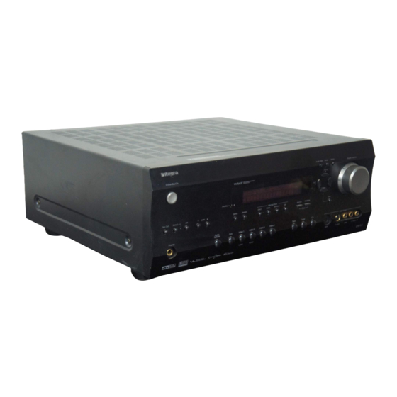
AV Receiver
DTR-6.4/5.4
Instruction Manual
Thank you for purchasing the
Please read this manual thoroughly before
making connections and plugging in the unit.
Following the instructions in this manual will
enable you to obtain optimum performance and
listening enjoyment from your new AV Receiver.
Please retain this manual for future reference.
AV Receiver.
Contents
(Advanced Settings)
Appendix
2
8
30
36
52
62
74
E
n
Advertisement
Table of Contents

Related Manuals for Integra DTR-6.4/5.4


Summary of Contents for Integra DTR-6.4/5.4
-
Page 1: Table Of Contents
AV Receiver. Please retain this manual for future reference. Before using Facilities and connections Setting up your DTR-6.4/5.4 Enjoying Music and Movies (Basic Settings) Configuring your DTR-6.4/5.4 (Advanced Settings) AV Receiver. -
Page 2: Important Safety Instructions
WARNING: TO REDUCE THE RISK OF FIRE OR ELECTRIC SHOCK, DO NOT EXPOSE THIS APPLIANCE TO RAIN OR MOISTURE. CAUTION: TO REDUCE THE RISK OF ELECTRIC SHOCK, DO NOT REMOVE COVER (OR BACK). NO USER-SERVICEABLE PARTS INSIDE. REFER SERVICING TO QUALIFIED SERVICE PERSONNEL. -
Page 3: Precautions
Though the color varies, the specifications and operations are the same. Supplied accessories Check that the following accessories are supplied with the DTR-6.4/5.4. AM loop antenna × 1 FM indoor antenna × 1 Remote controller × 1 Speaker cable label ×... -
Page 4: Before Using
Configuring the input settings suitable for your connection ...34 To change the display of the input source from TAPE to MD ...35 Enjoying Music and Movies (Basic Settings) Enjoying music or videos with the DTR-6.4/5.4 ... 36 Basic operation...36 Temporarily turning off the sound...37 Listening with headphones...37... -
Page 5: Configuring Your Dtr-6.4/5.4
...60 Settings available when you set “Dolby Pro Logic II Music” for your listening mode ...60 Settings available when you set an Integra-specific surround mode for your listening mode...60 Settings available when you play monaural signal ...61 Settings available when you set “Theater-Dimensional” for your listening mode ...61... -
Page 6: Features
Features DTR-6.4 Amplifier Features 100 W × 2 (Front)/ 100 W (Center)/ 100 W × 2 (Surround)/ 100 W (Surround Back) at 8 ohms, 20 Hz - 20 kHz, 0.08 % THD (FTC rated) Wide Range Amplifier Technology (WRAT) State-of-the-art linear PCM 192 kHz/24-bit DACs for All channels Optimum gain volume circuitry A-BUS Output for Second Zone... -
Page 7: Before Using This Unit
• Do not use a power cord other than the one supplied with the DTR-6.4/5.4. The power cord supplied is designed for use with the DTR-6.4/5.4 and should not be used with any other device. • Never have the power cord disconnected from the DTR-6.4/5.4 while the other end is plugged into the wall outlet. -
Page 8: Index Parts And Facilities
Index parts and facilities Here is an explanation of the controls and displays on the front panel of the DTR-6.4/5.4. DTR-6.4 Front panel DTR-5.4 Front panel... - Page 9 In the standby state, the display is turned off and the DTR-6.4/5.4 cannot be operated. Standby indicator [7, 29] Lights when the DTR-6.4/5.4 is in the standby state and when a signal is received from the remote controller. Display button [38] Press to display information about the current input source signal.
-
Page 10: Front Panel Display
Rec Out, Zone 2, Off, Level / buttons, and Zone 2 indicator [49, 50] The Rec Out and Zone 2 buttons allow you to use the DTR-6.4/5.4 to output to a remote zone (Zone 2) or to another component for recording (Rec Out). -
Page 11: Rear Panel
(Zone 2) if one has one. ANTENNA [24, 25] These jacks are for connecting the FM indoor antenna and AM loop antenna that are supplied with the DTR-6.4/5.4. A-BUS Ready [28] Use these terminals to connect the multi-home extension kit of the A-BUS system. -
Page 12: Remote View And Buttons
Index parts and facilities MONITOR OUT VIDEO/S VIDEO [19] These jacks are for connecting to the video input jacks on television monitors or projectors. IR IN/OUT [27] These connectors are for connecting the remote sensor of a multi- room kit (sold separately). PRE OUT ZONE 2 [26] When using the power amplifier for Zone 2 speakers, connect the power amplifier to these terminals. - Page 13 5.4 in standby and does not turn the power completely off. Sleep button [37] Press to set the sleep function. The Sleep button enables you to set the DTR-6.4/5.4 to turn off automatically after a specified time period. Macro 1, 2 button [70, 72, 73] Press to program or execute the macro function.
-
Page 14: About Home Theater
Enjoying Home Theater The DTR-6.4/5.4 has many excellent features to recreate clear three-dimensional sound image and lively sound movement. This enables you to easily enjoy rich sound effects just like you were in a theater or concert hall at home. -
Page 15: Av Cables And Connectors
AV cables and connectors • Be sure to always refer to the instructions that came with the component that you are connecting. • Do not plug in the power cord until all connections have been properly made. • For input jacks, red connectors (marked R) are used for the right channel, white connectors (marked L) are used for the left channel, and yellow connectors (marked V) are used for video connection. -
Page 16: Connecting Speakers
For locating speakers, see “About Home Theater” on page 14 and “Surround back speaker placement” on this page. Connect only speakers with an impedance between 6 and 16 Ω to the DTR-6.4/5.4. Connecting speakers with an impedance lower than 6 Ω may damage the amplifier. -
Page 17: Using The Speaker Cable Labels
30 degrees. Using the speaker cable labels The positive speaker terminals on the DTR-6.4/5.4 are color coded for easy identification. Attach the supplied speaker labels to the speaker cables, and then match the colors on the speaker cables to the corresponding terminals. -
Page 18: Connecting Your Av Components
Connecting your AV components Here is an explanation of typical ways to connect various components to the DTR-6.4/5.4. There are many ways that any one component can be connected, and it is up to you to decide which method best fits your situation. The directions given here are only one option and should only be thought of as such. -
Page 19: Connecting Your Video Components
Using an RCA video cable, connect the video input jack (composite) of the device to the MONITOR OUT V jack of the DTR-6.4/5.4. Or if the device has an S video input jack, connect it to the MONITOR OUT S jack of the DTR-6.4/5.4 using an S video cable. - Page 20 If the DVD player has both 5.1-channel audio outputs and 2- channel audio outputs, and you want to connect the DVD player only using the FRONT L/R jacks on the DTR-6.4/5.4, use the 2- channel audio output jacks on the DVD player.
- Page 21 VIDEO 1 V IN jack of the DTR-6.4/5.4 and connect the video input jack of the video cassette recorder to the VIDEO 1 V OUT jack of the DTR-6.4/5.4. Or if the video cassette recorder has S video input and output jacks, using S video cables, connect the S video output jack of the video cassette recorder to the VIDEO 1 S IN jack of the DTR-6.4/5.4 and connect...
- Page 22 (VIDEO 2) Using RCA video cables, connect the video output jack (composite) of the device to the VIDEO 2 V IN jack of the DTR-6.4/5.4 and connect the video input jack of the device to the VIDEO 2 V OUT jack of the DTR-6.4/5.4.
-
Page 23: Connecting The Power Cords From Other Devices
Caution: Make sure that the total capacity of the components connected to the DTR-6.4/5.4 does not exceed the capacity that is printed on the rear panel (e.g., TOTAL 120W). AC OUTLET AC OUTLETS... -
Page 24: Connecting Antennas
Connecting antennas To use the tuner of the DTR-6.4/5.4, it is necessary to prepare the supplied FM and AM antennas. • Adjustment and placement of the FM and AM antennas for better reception must be done while listening to a station broadcast. -
Page 25: Connecting An Fm Outdoor Antenna
Connecting antennas Connecting an FM outdoor antenna Make sure to follow the general rules given below: • Keep the antenna away from noise sources (neon signs, busy roads, etc.). • It is dangerous to put the antenna close to power lines. Keep it well away from power lines, transformers, etc. -
Page 26: Connecting The Remote Zone (Zone 2) Speakers
DTR-6.4/5.4 is actually located is referred to as the main room while the separate room is referred to as the remote zone (Zone 2). In addition, the IR IN terminal of the DTR-6.4/5.4 allows you to control the DTR-6.4/5.4 from the remote zone (Zone 2) with the remote controller even though the remote zone is physically separated (see next page). -
Page 27: Operating Components Not Reached By The Remote Controller Signals (Ir In)
IR IN terminal is output to the IR OUT terminal. The signal input from the remote sensor on the front of the DTR-6.4/5.4 will not be output to the IR OUT terminal. : Signal flow... -
Page 28: Miscellaneous Connections
Power on/ready function When the DTR-6.4/5.4 is in the standby state, if an component is turned on, the DTR-6.4/5.4 also turns on and the input source selected at the DTR-6.4/5.4 automatically switches to that component. -
Page 29: Connecting The Power
Diagram for DTR-6.4 Standby/On Standby indicator • Before you plug in the DTR-6.4/5.4, confirm that all connections have been made properly. • Turning on the power may cause a momentary power surge, which might interfere with other electrical equipment on the same circuit, such as computers. -
Page 30: Setup Menu
When making the various settings required to configure your DTR-6.4/5.4 for optimum performance, you can either use the OSD Menu that appears on your television monitor or you can use the display on the front of the DTR-6.4/5.4. The OSD Menu is a settings menu that is displayed on your TV monitor. -
Page 31: Buttons Used For Navigating Through The Menus
You can change settings in the Setup Menu using the buttons on the front panel and on the remote controller. The buttons on the remote controller correspond to those on the DTR-6.4/5.4 as shown below. Buttons on DTR-6.4/5.4 Buttons on remote controller... -
Page 32: Selecting The Appropriate Setting For Your Connection
IR IN Position (DTR-6.4)/ b. IR IN Position (DTR-5.4) Use this setting when you have a remote control sensor connected to the IR IN terminal. The setting in this menu tells the DTR-6.4/5.4 whether the remote control sensor is being used for operation of the DTR-6.4/5.4 in the main zone or the remote zone (Zone 2). -
Page 33: Speaker Configuration
Selecting the appropriate setting for your connection Speaker Configuration To create the optimum sound space for both visual and audio pleasure, it is necessary to set which type and size of speakers you will use. Once made, you will not need to change these settings unless you change the speaker configuration. -
Page 34: Configuring The Input Settings Suitable For Your Connection
When the default input settings does not suit your connection, perform the following procedures to configure your input settings. a. Digital Input This setting tells the DTR-6.4/5.4 which input source button on the front panel is connected with which digital input jack on the rear panel. -
Page 35: To Change The Display Of The Input Source From Tape To Md
Audio Sel Muting Angle Subtitle TV / VCR Level ENTER Random Audio Adjust Input Selector Pure A Direct Stereo SURR All ST Re-EQ Search Display Dimmer Zone 2 -- / --- Enter system functions will become enabled. DTR-6.4/5.4 Remote controller system... -
Page 36: Enjoying Music And Movies (Basic Settings)
DTR-6.4 Input source buttons Though the DTR-6.4/5.4 is often used to listen to the radio, it does not show you its true ability until it is used to play music or watch videos, DVDs, and the like. The DTR-6.4/5.4 has the latest and most state-of- the-art features to play back today’s technologies with the utmost in... -
Page 37: Temporarily Turning Off The Sound
Sleep Using the sleep time (remote controller only) The Sleep button enables you to set the DTR-6.4/5.4 to turn off Remote automatically after a specified time period. If you press it once, the controller DTR-6.4/5.4 will turn off after 90 minutes. -
Page 38: Switching The Display
While listening to or watching an input source, you can display the information regarding the type of source and signal being input by pressing the Display button on the DTR-6.4/5.4 or the remote controller. You can set separate video displays for when the input source is set to AM or FM broadcasts and for when it is set to anything else. -
Page 39: Selecting The Type Of Audio Input Signal
In such cases, try playing the source in the “DTS” selected. • The DTS indicator on the DTR-6.4/5.4 lights while a DTS source is played. When playback finishes and the DTS signal transmission stops, the DTR-6.4/5.4 remains in DTS mode and the DTS indicator remains lit. -
Page 40: Enjoying Dvd Multichannel Audio Playback
Direct (DTR-5.4) Basic operation When you made multichannel connection (5.1ch) between your DVD player and the DTR-6.4/5.4, you can enjoy analog multichannel audio playback. Make sure that your connection is identical to the connection shown in “Connecting a DVD Player with 5.1-Channel Output”... -
Page 41: Changing The Listening Mode (Dtr-6.4 Only)
Enjoying DVD multichannel audio playback To turn off the tone control: Press the Direct button. DTR-6.4 DTR-5.4 “Direct” appears on the display and the tone control is turned off. Changing the listening mode (DTR-6.4 only) Each time you press the Direct/Pure Audio button on the front panel, the display changes between “Direct”... -
Page 42: Listening To Radio Broadcasts
Listening to Radio Broadcasts One of the features of the DTR-6.4/5.4 that is most frequently used is its ability to play FM and AM broadcast radio stations. The DTR- 6.4/5.4 provides a number of listening modes perfect for listening to the radio and getting the most out of your audio system. -
Page 43: Presetting A Radio Station
Lights Erasing a preset radio station This can only be performed at the DTR-6.4/5.4. 1. Press the Tuner button and press the Preset preset radio station that you want to erase (see above). -
Page 44: Listening Modes
Listening Modes The DTR-6.4/5.4’s surround sound enables you to enjoy the presence of a movie theater or concert hall in your room. The configuration of the speakers is very important for the surround sound. Refer to “About Home Theater” on page 14. - Page 45 EX format. In this case, the sound actually output from the surround back channels depends on the source and may not fit your tastes. Integra-specific surround modes (DSP) Mono Movie This mode is suitable for playing back monaural recording such as old movie soundtracks.
-
Page 46: Selecting A Listening Mode (Dtr-6.4)
Listening Modes DTR-6.4 Listening mode buttons Selecting a listening mode (DTR-6.4) • Refer to pages 44 and 45 for more details of listening modes. • Refer to page 45 for sources and listening modes. • When playing Dolby Digital or DTS software, the listening mode will automatically change to Dolby Digital or DTS. -
Page 47: Selecting A Listening Mode (Dtr-5.4)
Listening Modes DTR-5.4 Listening mode buttons Selecting a listening mode (DTR-5.4) • Refer to pages 44 and 45 for more details of listening modes. • Refer to page 45 for sources and listening modes. • When playing Dolby Digital or DTS software, the listening mode will automatically change to Dolby Digital or DTS. -
Page 48: Fixing Playback To Specific Surround Mode
Listening Modes Surround (DTR-6.4) Fixing playback to specific surround mode • While playing back DTS sources Each time you press the SURR button, the DTS-ES setting switches from: Auto → On → Off. Auto: When a DTS source with a DTS-ES flag (ID signal for DTS-ES) is input, the listening mode changes automatically to DTS-ES Discrete 6.1 or DTS-ES Matrix 6.1. -
Page 49: Enjoying Music In The Remote Zone
-- / --- Enter Using the remote controller With the DTR-6.4/5.4 in the standby state, turn on the output to the remote zone (Zone 2): After pressing the Zone 2 button, press the On button within 5 seconds. The Zone 2 indicator lights. -
Page 50: Recording
Recording the input source (Rec Out selector) When using the DTR-6.4/5.4 to record a source, you must select that source to be output from the TAPE OUT jacks. Recording the same source that you are listening to: 1. -
Page 51: Recording Both The Audio And Video
Recording Recording both the audio and video The DTR-6.4/5.4 also allows you to record the audio and video signals output from the VIDEO OUT 1 and 2 jacks. 1. Press the input source button for the source you want to record. -
Page 52: Configuring The Speakers (Dtr-6.4)
Configuring the speakers (DTR-6.4) Setting the speaker distance from your normal listening position Set the distance between the listening position and the speakers. Setting the speaker distance equates the time the sound will take to reach the listening position from each speaker, resulting in more comfortable home theater experience. -
Page 53: Calibrating The Speaker Levels
Configuring the speakers (DTR-6.4) Calibrating the speaker levels Use this menu to set the volume for each speaker so that each volume is heard by the listener at the same level. This is especially important for speaker layouts where the left and right speakers are at different distances or in asymmetrical positions due to room designs and configurations. -
Page 54: Configuring The Speakers (Dtr-5.4)
Configuring the speakers (DTR-5.4) Setting the speaker distance from your normal listening position Set the distance between the listening position and the speakers. Setting the speaker distance equates the time the sound will take to reach the listening position from each speaker, resulting in more comfortable home theater experience. -
Page 55: Calibrating The Speaker Levels
Configuring the speakers (DTR-5.4) Calibrating the speaker levels Use this menu to set the volume for each speaker so that each volume is heard by the listener at the same level. This is especially important for speaker layouts where the left and right speakers are at different distances or in asymmetrical positions due to room designs and configurations. -
Page 56: Input Setup
Volume setting allows you to preset a volume level for each input source separately so that when you do switch from one input source to another, the DTR-6.4/5.4 adjusts the volume accordingly and the volume stays the same. 1. Select the desired input source. -
Page 57: Configuring The Listening Modes Frequently You Use
You can preset the listening mode for individual input source. The listening mode will be reset to the mode you set here after turning on the DTR-6.4/5.4 even if you change the listening mode using the Listening Mode buttons. 1. Select the desired input source. -
Page 58: Preference
2. Use the cursor buttons to select “6. Preference” and then press the ENTER button. The “Preference” menu appears. DTR-6.4/5.4 * Menu ***************** 1.Speaker Config 6.Preference 2.Speaker Distance *********************** 3.Level Calibration... -
Page 59: Audio Adjust
Audio Adjust These settings are enabled depending on the listening mode or input signal. Select the listening mode for which you make the Audio Adjust settings before performing the procedures. Setup Procedure 1. Press the Audio Adjust button. The Audio Adjust settings appear in the front display and on the monitor. -
Page 60: Setting Available When You Play Mono, 2-Channel Or 96 Khz Format Signal
Pro Logic II Music mode is “3.” This allows you to easily distinguish the Pro Logic II Music mode from the Pro Logic II Movie mode whose setting is automatically set to “0.” Settings available when you set an Integra-specific surround mode for your listening mode Front Effect Some live recordings contain acoustic reverberation. -
Page 61: Settings Available When You Play Monaural Signal
Audio Adjust Reverb Level This setting allows you to adjust the depth of acoustic reverberation to match the playback source material, the acoustics of your room, and such other factors. Select from the three settings “Low,” “Mid,” and “High.” Reverb Time Adjust the reverb time to match the source being played back and the acoustics of the room. -
Page 62: Remote Controller
Overview The RC-534M/517M remote controller is a useful tool that can not only operate the DTR-6.4/5.4, but also all the other components of your home theater as well. To operate any component, first press the Mode button on the remote controller that corresponds to the component that you wish to control. -
Page 63: Controlling An Integra/Onkyo Dvd Player
The DVD Mode button lights. 2. Press the desired operation button. The buttons shaded in the figure to the left are the operation buttons that can be used to control an Integra/Onkyo DVD player. Operation buttons: On: Turns DVD player on and off Standby: Turns DVD player off (Some sets may not respond to this button. -
Page 64: Controlling An Integra/Onkyo Cd Player
Standby 2. Press the desired operation button. The buttons shaded in the figure to the left are the operation buttons that can be used to control an Integra/Onkyo compact disc player. Operation buttons: On: Turns on and off the compact disc player (same as Standby... -
Page 65: Controlling An Onkyo Md Recorder
ENTER: Enters the settings You may also use the following buttons: Numeric keys : Adjusts volume at DTR-6.4/5.4 Muting: Activates muting function at DTR-6.4/5.4 Enter Note: The SAT/MD button is used for operating satellite tuners and Onkyo MD recorders. Be aware that if you enter the preset code for a satellite tuner as shown on page 66, then this button cannot be used to operate Onkyo MD recorders. -
Page 66: Entering A Pre-Programming Code
613. No. 600: This code is for Integra/Onkyo DVD players that have an terminal that you are connecting to the DTR-6.4/5.4 with an cable. You will then operate the DVD player by pointing the remote controller at the remote control sensor on the DTR-6.4/5.4. -
Page 67: Pre-Programming Codes
BRAND SETTING No. DENON 602, 609 HITACHI KENWOOD MAGNAVOX 606, 613 MARANTZ MITSUBISHI 608, 613 INTEGRA/ONKYO 600, 601, 613 PANASONIC PIONEER PROSCAN SONY TOSHIBA YAMAHA 609, 614 ZENITH 613, 615 BRAND SETTING No. -
Page 68: Operating Your Programmed Remote Controller
ENTER: Confirms selection Menu: Displays menu 0,1 to 9: Numeric keys ENTER: Confirm You may also use the following buttons: Muting: Activates the muting function at the DTR-6.4/5.4 Numeric keys Enter Cable Mode (Cable Mode) 1. Press the Cable Mode button. -
Page 69: Vcr Mode (Vcr Mode)
0,1 to 9, +10: Numeric keys You may also use the following buttons: Numeric keys : Adjusts the volume at the DTR-6.4/5.4 Muting: Activates the muting function at the DTR-6.4/5.4 TV Mode (TV Mode) 1. Press the TV Mode button. The TV Mode button lights. -
Page 70: Programming The Commands Of Remote Controllers For Other Devices Into The Remote Controller
Programming the commands of remote controllers for other devices into the remote controller 2 to 6 inches (5 to 15 cm) RC-534M Disc Audio Sel Muting Angle Subtitle TV / VCR Level Random Audio Adjust Input Selector Pure A Direct Stereo SURR All ST... -
Page 71: Erasing The Programmed Command From One Button
You may, however, use these buttons to program the codes for other remote controllers. If you wish to restore the Integra preset codes after you program new codes, you must first erase the new codes. • The remote controller has 357 memory slots (7 modes × 51 buttons). -
Page 72: Using The Macro Function
(up to 16) on the remote controller into a single button. The series of operations are then called a macro. For example, to play a compact disc player connected to the DTR-6.4/5.4 normally, you must perform the following steps: 1. -
Page 73: Erasing A Macro From The Macro 1 (Or 2) Button
Using the macro function RC-534M Macro 1 Disc Audio Sel Muting Angle Subtitle TV / VCR Level Random Audio Adjust Input Selector Pure A Direct Stereo SURR All ST Re-EQ Search Display Dimmer Zone 2 -- / --- Enter RC-534M Disc Audio Sel Muting... -
Page 74: Specifications (Dtr-6.4)
Specifications AMPLIFIER SECTION Continuous average power output (FTC) 100 W per channel min. RMS at 8 Ω, All channels: 2 channels driven from 20 Hz to 20 kHz with no more than 0.08% total harmonic distortion. 125 W min. RMS at 6 Ω, 2 channels driven from 1 kHz with no more than 0.1% total harmonic distortion. -
Page 75: Specifications (Dtr-5.4)
Specifications (DTR-5.4) AMPLIFIER SECTION Continuous average power output (FTC) 85 W per channel min. RMS at 8 Ω, All channels: 2 channels driven from 20 Hz to 20 kHz with no more than 0.08% total harmonic distortion. 110 W min. RMS at 6 Ω, 2 channels driven from 1 kHz with no more than 0.1% total harmonic distortion. -
Page 76: Troubleshooting Guide
Troubleshooting guide If a problem occurs while you are using the remote controller, first try to operate the controls on the front panel of the DTR-6.4/5.4 to make sure that it is not due to a malfunction (or worn out batteries) in the remote controller. -
Page 77: Video And Audio
DTR-6.4/5.4. © Point the remote controller at the remote sensor of the DTR- 6.4/5.4 (see page 7). • Remote controller is too far from the DTR-6.4/5.4. © Operate the remote controller within 16 feet (5 meters) (see page 7). • Remote controller is functioning in a different mode ©... -
Page 78: If One Of The Messages Shown Below Appears
* To reset the surround mode and other settings to the factory default settings, hold down the Video 1 button with the DTR- 6.4/5.4 turned on and then press the Standby/On button. “CLEAR” appears in the front display and the DTR-6.4/5.4 enters the standby state. -
Page 79: Memo
Memo... - Page 80 Integra Division of ONKYO U.S.A. CORPORATION 18 Park Way, Upper Saddle River, N.J. 07458, U.S.A. Tel: 201-785-2600 Fax: 201-785-2650 http://www. integrahometheater.com Integra Division of ONKYO CORPORATION Sales & Product Planning Div. : 2-1, Nisshin-cho, Neyagawa-shi, OSAKA 572-8540, JAPAN Tel: 072-831-8111 Fax: 072-831-8124 SN 29343499 ©...
Need help?
Do you have a question about the DTR-6.4/5.4 and is the answer not in the manual?
Questions and answers
How to reset to open box
To reset the Integra DTR-6.4/5.4 to factory default settings, follow these steps:
1. Ensure the DTR-6.4/5.4 is turned on.
2. Press and hold the Video 1 button.
3. While holding Video 1, press the Standby/On button.
4. The word "CLEAR" will appear on the front display.
5. The unit will enter standby mode, and all settings, including surround mode and presets, will be reset to factory defaults.
This answer is automatically generated
I can not get front speakers to work, with one center speaker,
To ensure the front speakers work properly with the Integra DTR-6.4/5.4 while using one center speaker:
1. Check Speaker Connections: Verify that the front left, front right, and center speakers are correctly connected to the receiver's corresponding terminals.
2. Speaker Configuration: Ensure the speaker configuration in the receiver's settings matches the setup with three speakers (front left, front right, and center). This is a 3-channel surround playback configuration.
3. Volume Calibration: Use the "Level Calibration" menu to balance the sound. Follow these steps:
- Access the "Level Calibration" menu.
- Emit pink noise from each speaker and adjust the volume levels using the Level buttons so all speakers produce sound at the same level.
4. Mode Selection: Confirm the correct playback mode is selected to distribute audio appropriately between the center and front speakers.
If these steps do not resolve the issue, there may be a hardware fault requiring further inspection.
This answer is automatically generated