Table of Contents
Advertisement
SERVICE MANUAL
SERVICE MANUAL
AV RECEIVER
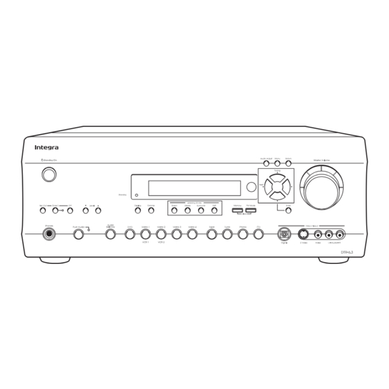
DTR-6.3
MODEL
Black model
BMDD
120V AC, 60Hz
SAFETY-RELATED COMPONENT
WARNING!!
COMPONENTS IDENTIFIED BY MARK
SCHEMATIC DIAGRAM AND IN THE PARTS LIST ARE
CRITICAL FOR RISK OF FIRE AND ELECTRIC SHOCK.
REPLACE THESE COMPONENTS WITH ONKYO
PARTS WHOSE PART NUMBERS APPEAR AS SHOWN
IN THIS MANUAL.
MAKE LEAKAGE-CURRENT OR RESISTANCE
MEASUREMENTS TO DETERMINE THAT EXPOSED
PARTS ARE ACCEPTABLY INSULATED FROM THE
SUPPLY CIRCUIT BEFORE RETURNING THE
APPLIANCE TO THE CUSTOMER.
Ref. No. 3733
June, 2002
ON THE
DTR-6.3
RC-481M
Advertisement
Table of Contents

Related Manuals for Integra DTR-6.3


Summary of Contents for Integra DTR-6.3
- Page 1 DTR-6.3 Ref. No. 3733 SERVICE MANUAL SERVICE MANUAL June, 2002 AV RECEIVER DTR-6.3 MODEL Black model BMDD 120V AC, 60Hz RC-481M SAFETY-RELATED COMPONENT WARNING!! COMPONENTS IDENTIFIED BY MARK ON THE SCHEMATIC DIAGRAM AND IN THE PARTS LIST ARE CRITICAL FOR RISK OF FIRE AND ELECTRIC SHOCK.
-
Page 2: Specifications
DTR-6.3 SPECIFICATIONS AMPLIFIER SECTION TUNER SECTION Continuous average power output (FTC) All channels: 100 W per channel min. RMS at 8 ohm, Tuning range: 87.5 -108.0 MHz (50-kHz steps) 2 channels driven from 20 Hz to 20 Usable sensitivity kHz with no more than 0.08% total Mono: 11.2 dBf, 1.0 µV (75 ohm IHF) -
Page 3: Service Procedures
DTR-6.3 SERVICE PROCEDURES 1. Replacing the fuses 3. Safety-check out (Only U.S.A. model) This symbol located near the fuses indicates that the After correcting the original service problem, perform the fuse used is fast operating type. For continued protection against following safety check before releasing the set to the customer. -
Page 4: Exploded View Parts List
DTR-6.3 CAUTION: Replacement for transistor of mark *, if necessary EXPLODED VIEW-PARTS LIST NOTE: THE COMPONENTS IDENTIFIED BY MARK ! must be made from the same beta group (h ) as ARE CRITICAL FOR RISK OF FIRE AND the original type. -
Page 5: Exploded View
DTR-6.3 EXPLODED VIEW P101 P2602 F901 P7501 Q6050 F6902 Q6060 F6901 Q6055 P7502 Q6065 P6931 T901 F9501... -
Page 6: Block Diagram
DTR-6.3 BLOCK DIAGRAM DIGITAL AUDIO INPUT FRONT DIGITAL AUDIO OUTPUT OPTICAL OPTICAL COAXIAL +2.5V FLASH ROM 4M-BIT MX23L4000 +3.3V 12.288MHZ OPTICAL 1 COAXIAL MEMORY OPTICAL 2 (DD-EX) 50KLPF (AC-3,DTS) AK4586 (DTS-ES) (1/3) (PLII,NEO:6) CS493292 DAUX 50KLPF 96/24 192/24 FM/AM IR 56K... - Page 7 DTR-6.3 BLOCK DIAGRAM MULTICHANNEL INPUT / DVD IN HEAD PHONE DVD/ R DVD/ L HPEN ZONE 2 BD3811K1 (2/2) MASTER VOLUME Power Amplifier BASS/TREBLE MUTE BOOST SW->L +29dB BYPASS BASS/TREBLE MUTE SW->R +29dB BYPASS MCSL MUTE PREOUT FRONT SPEAKERS +29dB...
-
Page 8: Printed Circuit Board View
DTR-6.3 PRINTED CIRCUIT BOARD VIEW 6-2 Video section 2 P2060 P241 P2060 COMPONENT2 COMPONENT1 COMPONENT P241 Soldering side RL241 Component side J2064 J2061 J2065 RL242 J2062 P242A P243A Component video terminal PC board P105A J2018 P107A P106A R2079 J2013 C2245... - Page 9 DTR-6.3 PRINTED CIRCUIT BOARD VIEW 6-1 Video terminal PC board Video section 1 U201 U202 U203 P208 P203 P202 P201 P2004 P206 P206 U203 U201 U202 P208 L242 Q2033 J205 P202 J210 P203 P201 COAX Q2033 J201 RX-2 RX-1 L242...
- Page 10 DTR-6.3 PRINTED CIRCUIT BOARD VIEW 5-2 Power supply and output sections C9591 2.5A/125V P7502B F9501A F9501B FAC1 HPL1 FAC2 F9501 HPR1 R9593 P995B 25137477 J9509 NCPS-7477 HPR1 J9506 J9511 JL9501A HPL1 Secondary circuit PC board NCETC-7478 25137478 P6810 P6811 J12A...
- Page 11 DTR-6.3 PRINTED CIRCUIT BOARD VIEW 5-1 Power supply and output sections NCETC-7476 25137476 JL6804C J6712 J6711 JL6810A J6730 J6710 JL6805C J6739 J6752 JL6803C J6731 J6720 J6721 J6708 J6740 J6748 J6736 J6718 R6860 J6709 J6724 J6719 L6851 L6850 J6707 L6852 J6725...
-
Page 12: Power Amplifier Section
DTR-6.3 PRINTED CIRCUIT BOARD VIEW 4-3 Power amplifier section 3 J6127 J6082 J6016 Q6012 Q6011 Q6010 Q6052 Q6061 Q6051 Q6062 Q6060 Q6050 R6092 R6521 R6091 R6090 R6511 J6034 R6510 J6134 J6122 J6099 J6081 J6076 J6037 J6036 J6123 J6077 J6014 J6102... - Page 13 DTR-6.3 PRINTED CIRCUIT BOARD VIEW 4-2 Power amplifier section 2 J6192 J6174 J6147 J6204 R6512 Q6015 Q6014 Q6013 Q6054 Q6053 Q6065 Q6055 Q6064 Q6063 Q6062 R6094 R6093 R6522 R6513 J6145 R6095 J6199 J6188 J6180 J6173 J6168 J6159 J6155 J6146 J6189...
- Page 14 DTR-6.3 PRINTED CIRCUIT BOARD VIEW 4-1 Q5035 C5005 Power amplifier section 1 R5195 R5005 C5015 R5185 C5115 R5165 R5015 R5135 R5025 J5052 C5095 C5045 J5053 R5105 Q5055 R5085 R5075 Q5015 R5175 R5155 R5145 J5091 J5090 C5004 R5194 R5004 C5014 R5184...
-
Page 15: Component Side
DTR-6.3 PRINTED CIRCUIT BOARD VIEW 7 Input/Output sections NCAF-7473 P2064 25137473 C2071 C2073 C2069 C2065 C2216 C2214 C2066 C2070 J2071 C2074 C2213 C2072 C2215 C2256 J2207 Component side J2209 Q2205 C2218 J2208 C2255 C2219 J2218 J2214 R2065 J2215 C2220 R2067... -
Page 16: Front Panel Section
DTR-6.3 PRINTED CIRCUIT BOARD VIEW 3 Front panel section JL7502B P2501C P7705 P2555 P209C 25137468 HPL2 NCVD-7468 P2553 HPR2 HPDET P2553 P2554 25137463 NCETC-7463 P2554 Component side Component side C7702 L7703 R2552 R2551 R2555 C2553 R2553 R2554 C2554 L7704 HPL2... -
Page 17: Dsp Section
DTR-6.3 PRINTED CIRCUIT BOARD VIEW 2-4 DSP section Q9503 R9503 R729 P2601A R728 R727 R726 D9509 C718 C717 R707 C716 C707 L703 C713 R708 R723 R709 L701 C714 L706 R710 C715 R711 C729 Q705 C709 L702 C705 Q705 Q702 Q704... - Page 18 DTR-6.3 PRINTED CIRCUIT BOARD VIEW 2-3 DSP section R320 C320 R321 C321 P305 R318 C318 R319 C319 C326 R316 R317 R314 R854 R848 R838 R828 C314 R855 R849 R839 R829 R315 R852 R846 R836 R826 R350 C315 R853 R847 R837...
- Page 19 DTR-6.3 PRINTED CIRCUIT BOARD VIEW 2-2 DSP section Q9503 R9503 R729 P2601A R728 R727 R726 D9509 C718 C717 R707 C716 C707 L703 C713 R708 R723 R709 L701 C714 L706 R710 C715 R711 C729 Q705 C709 L702 C705 Q705 Q702 Q704...
- Page 20 DTR-6.3 PRINTED CIRCUIT BOARD VIEW 2-1 DSP section R320 C320 R321 C321 P305 R318 C318 R319 C319 C326 R316 R317 R314 R854 R848 R838 R828 C314 R855 R849 R839 R829 R315 R852 R846 R836 R826 R350 C315 R853 R847 R837...
- Page 21 DTR-6.3 PRINTED CIRCUIT BOARD VIEW FROM SOLDERING SIDE 1-2 P7502A J7525 NCDIS-7461 J7512 25137461B STANDBY S7641 C7540 JL7501B NCSW-7462 25137462 RL7701 C7521 C7524 J7523 S7501 STANBY D7581 S7501 J7522 Component side Volume PC ZONE2 D7583 SPK-B LEVEL-UP LEVEL-DOWN ZONE2 board...
- Page 22 DTR-6.3 PRINTED CIRCUIT BOARD VIEW FROM SOLDERING SIDE 1-1 P7504 AUDIO RETURN MENU ADJUST P7501A J7551 J7549 J7545 R7591 R7592 R7593 S7613 S7612 S7611 Q7501 TUNING-UP S7614 Q7501 J7558 PRESET U7501 J7537 J7538 PRESET-DOWN J7523 S7615 S7616 J7533 TUNING-DOWN S7617...
-
Page 23: Schematic Diagram
DTR-6.3 SCHEMATIC DIAGRAM 1-1 Display section NADIS-7461 Q7501 HNA-16MM39T P46/FIP38 P47/FIP39 FIP18 62 61:FIP19 P50/FIP40 FIP17 63 P51/FIP41 FIP16 64 P52/FIP42 FIP15 65 P53/FIP43 FIP14 66 P54/FIP44 FIP13 67 P55/FIP45 FIP12 68 Q7502 P56/FIP46 FIP11 69 P57/FIP47 FIP10 70 UPD780233GC... - Page 24 DTR-6.3 SCHEMATIC DIAGRAM 1-2 Display section TO NAPS-7477 (SCH.-6) P7502A AC6V AC6V Except D C7505 473Z HPDET HPR2 RL7701 HPL2 D7702 1SS352 OR 1SS355 D7506 D7701 1SS352 OR 1SS355 Q7701 C7540 1SS352 KRC102S 220/6.3 OR 1SS355 D7507 1SS352 OR 1SS355...
- Page 25 DTR-6.3 SCHEMATIC DIAGRAM 2-1 DSP section 1 ( S C H . - 3 ) ( S C H . - 9 ) ( S C H . - 9 ) ( S C H . - 9 ) F R O N T V I D E O - 4 I N...
- Page 26 DTR-6.3 SCHEMATIC DIAGRAM 2-2 DSP section 2 3 3 0 J 3 3 0 1 0 / 1 6 A G N D 1 O U T 2 1 3 N J M 4 5 6 5 M I N 2...
- Page 27 DTR-6.3 SCHEMATIC DIAGRAM 2-3 DSP section 3 (SCH.-9) O N A E T C - 7 4 8 6 T O T U N E R P A C K P 1 0 1 D 9 5 0 1 - 9 5 0 3 :...
- Page 28 DTR-6.3 SCHEMATIC DIAGRAM 2-4 DSP section 4 D I R I N T 1 5 1 : P 4 4 / A D 4 7 6 : P 7 2 / A N I 2 S P Z 2 / S P B...
- Page 29 DTR-6.3 SCHEMATIC DIAGRAM 3 Front panel section N A V D - 7 4 6 8 V 4 C V 4 Y V - 4 R 2 5 5 1 V 4 - L 3 3 0 V 4 E...
-
Page 30: Power Amplifier Section
DTR-6.3 SCHEMATIC DIAGRAM 4-1 Power amplifier section 1 N A A F - 7 4 8 3 P 4 0 4 R 5 1 6 3 5 0 . 7 V 1 2 0 ( 1 / 4 W ) - Page 31 DTR-6.3 SCHEMATIC DIAGRAM 4-2 Power amplifier section 2 T O N A D G - 7 4 6 0 T O N A D G - 7 4 6 0 T O N A A F - 7 4 7 4 ( S C H .
- Page 32 DTR-6.3 SCHEMATIC DIAGRAM 5-1 Power amplifier section 3 N A A F - 7 4 7 4 [ 5 5 . 5 V ] Q 6 0 3 3 R 6 1 6 3 R 6 0 8 3 3 3 K...
- Page 33 DTR-6.3 SCHEMATIC DIAGRAM 5-2 Power amplifier section 4 [ 5 5 . 5 V ] Q 6 0 3 0 R 6 1 6 0 R 6 0 8 0 3 3 K N A A F - 7 4 7 4...
-
Page 34: Power Supply Section
DTR-6.3 SCHEMATIC DIAGRAM 7 Power supply section C 9 2 2 N A P S - 7 4 8 4 2 2 0 / 3 5 C 9 2 1 + 1 3 V S 1 5 V 2 2 3 Z... -
Page 35: Output Section
DTR-6.3 SCHEMATIC DIAGRAM 6 Output section NAETC-7476 P 6 8 0 3 L 6 8 5 0 S 1 . 3 C C 6 6 5 0 1 0 3 J R 6 8 5 0 D 6 6 5 0... - Page 36 DTR-6.3 SCHEMATIC DIAGRAM 8 Video section N A V D - 7 4 6 4 R 2 4 3 C 2 5 1 1 0 4 Z R 2 5 1 0 0 0 J R 2 0 5 4...
- Page 37 DTR-6.3 SCHEMATIC DIAGRAM 9 N A E T C - 7 4 6 6 Q 2 2 5 7 C 2 2 5 5 3 . 9 K 2 2 0 R 2 2 5 5 4 7 / 1 6...
- Page 38 DTR-6.3 PC BOARD-CONNECTION VIEW H E A D P H O N E V O L U M E N A E T C - 7 4 6 3 N A S W - 7 4 6 2 ( S C H . - 3 ) ( S C H .
- Page 39 DTR-6.3 PC BOARD-CONNECTION VIEW J L 6 9 5 2 B J L 6 9 5 1 B A D P H O N E N A E T C - 7 4 6 3 P R I M A R Y ( S C H .
-
Page 40: Wiring View
DTR-6.3 WIRING VIEW JL6805C JL6804C JL6801A JL6803C Page 23 NAETC-7476 SPEAKER TERMINAL NAETC-7476 PC BOARD P6804 P6803 S902 E921 Page 24 P911 P6840 JL6805A JL6803A P915A P917 P918 NAAF-7474 AC-G POWER AMPLIFIER Page 23 PC BOARD NAPS-7484 PRIMARY CIRCUIT P909... - Page 41 DTR-6.3 WIRING VIEW NAETC-7478 PRE. OUTPUT TERMINAL PC BOARD : Flat cable Page 24 : Jumper Wire NAETC-7466 NAETC-7466 : Socket A-BUS CIRCUIT A-BUS CIRCUIT PC BOARD PC BOARD : PC board to PC board Page 28 P404C P2207B U203...
-
Page 42: Printed Circuit Board-Parts List
DTR-6.3 PRINTED CIRCUIT BOARD-PARTS LIST 1 MAIN CIRCUIT PC BOARD (NADG-7460-1R) CIRCUIT NO. PART NO. DESCRIPTION CIRCUIT NO. PART NO. DESCRIPTION Capacitors C101,C102 394680337 3.3uF,50V,Elect. Q301 22241761R3 BD3811K1 C300,C301 374722215 220pF+/-10%,50V,Plastic Q302 22241785R2 BD3812F C316,C317 374722215 220pF+/-10%,50V,Plastic Q303 22241787R3 TC9274F-020... - Page 43 DTR-6.3 PRINTED CIRCUIT BOARD-PARTS LIST 2 CIRCUIT NO. PART NO. DESCRIPTION CIRCUIT NO. PART NO. DESCRIPTION Sockets Capacitors JL9501B 25050269 NSCT-5P97 C7502 394684707 47uF,50V,Elect. P101 25052211 NSCT-15P2108 C7514,C7705 394621017 100uF,6.3V,Elect. 25051822 NSCT-15P1609 C7521,C7540 394622217 220uF,6.3V,Elect. P2062B 25052203 or NSCT-7P2100 or...
- Page 44 DTR-6.3 PRINTED CIRCUIT BOARD-PARTS LIST 3 CIRCUIT NO. PART NO. DESCRIPTION COMPONENT VIDEO PC BOARD (NAVD-7465-1P) Photo coupler CIRCUIT NO. PART NO. DESCRIPTION Q2033 24120080 PC817X Transistor U201,U202 24120083 or GP1FA550RZ or Q241 2216175R2 or KTC3875-GR or 24120086 GP1FA551RZ 2213145R2...
- Page 45 DTR-6.3 PRINTED CIRCUIT BOARD-PARTS LIST 4 CIRCUIT NO. PART NO. DESCRIPTION POWER AMPLIFIER PC BOARD (NAAF-7474-1P) Terminals CIRCUIT NO. PART NO. DESCRIPTION P2202 25045598 HEC0470-01-630 Transistors P2203,P2204 25045647 HSJ1002-01-1020 Q6010~Q6015 2213284 or 2SC1740S-R or P2206 25045647 HSJ1002-01-1020 Q6020~Q6025 2213285 2SC1740S-S...
- Page 46 DTR-6.3 PRINTED CIRCUIT BOARD-PARTS LIST 5 CIRCUIT NO. PART NO. DESCRIPTION SECONDARY CIRCUIT PC BOARD (NAPS-7477-1P) Resistors CIRCUIT NO. PART NO. DESCRIPTION R6040~R6045 5210258 N06HR1KBC,Trimming Capacitor R6070~R6075 415471214 120ohm+/-5%,1/4W,NF carbon C9591 374721044 0.1uF+/-5%,50V,Plastic R6080~R6085 415470224 2.2ohm+/-5%,1/4W,NF carbon Resistors R6090~R6095 415470224 2.2ohm+/-5%,1/4W,NF carbon...
- Page 47 DTR-6.3 PRINTED CIRCUIT BOARD-PARTS LIST 6 CIRCUIT NO. PART NO. DESCRIPTION CONNECTOR PC BOARD (NAETC-7486-1T) Capacitors CIRCUIT NO. PART NO. DESCRIPTION C5000~C5005 374721015 100pF+/-10%,50V,Plastic Transistors C5010~C5015 393341017 100uF,16V,Elect. Q2031,Q2032 2215960 or KRC102M or C5020~C5025 394681007 10uF,50V,Elect. Q2225 2213290 DTC114ES C5040~C5045 393342217 220uF,16V,Elect.
-
Page 48: Packing Procedures
DTR-6.3 PACKING PROCEDURES Bottom Accessary bag P901 Put the label 81 between page 2 and page 3 of instruction manual E. Speaker Cable REF.NO. PART NO. DESCRIPTION 29092052 29100153 1020x720,Polybag 29110149 Tape, cellophane 29110148 PP tape 29100097-1A 350*250,Polybag 29053892 Carton box... - Page 49 Tel: 072-831-8111 Fax: 072-833-5222 http://www.onkyo.co.jp/ Integra Division of ONKYO U.S.A. CORPORATION 18 Park Way, Upper Saddle River, N.J. 07458, U.S.A. Tel: 201-785-2600 Fax: 201-785-2650 E-mail: integra@onkyousa.com http://www.integrahometheater.com ONKYO EUROPE ELECTRONICS GmbH Industriestrasse 20, 82110 Germering, GERMANY Tel: 089-849-320 Fax: 089-849-3265 E-mail: info@onkyo.de...
Need help?
Do you have a question about the DTR-6.3 and is the answer not in the manual?
Questions and answers