DataCard SR200 Service Manual
Hide thumbs
Also See for SR200:
- User manual (138 pages) ,
- Installation manual (94 pages) ,
- Hardware and driver installation manual (50 pages)
Advertisement
Table of Contents
- 1 Service Manual
- 2 Proprietary Notice
- 3 Trademark Acknowledgments
- 4 Revision Log
- 5 Specifications
- 6 Section 1 Precaution
- 7 Section 2 Specific Service Instructions
- 8 Section 3 Disassembly
- 9 Section 4 Adjustment
- 10 Section 5 Trouble Shooting
- 11 Ink Error
- 12 Wiring Diagram
- 13 Block Diagram
- 14 Troubleshooting Sheet
- Download this manual
Advertisement
Table of Contents

Subscribe to Our Youtube Channel
Related Manuals for DataCard SR200


Summary of Contents for DataCard SR200
-
Page 1: Service Manual
Datacard SR200/SR300 ® Printer Service Manual April 2010 Part No. 539898-001, Rev A... -
Page 2: Proprietary Notice
All information herein is the property of DataCard Corporation. All unauthorized use and reproduction is prohibited. Trademark Acknowledgments Datacard is a registered trademark and service mark of DataCard Corporation in the United States and other countries. All other product names are the property of their respective owners. -
Page 3: Specifications
SPECIFICATION SR200, SR300 Specifications Recording system Dye sublimation retransfer Paper feed mode Automatic Recording density 300 dpi Reproduction gradation 256 levels each for Y, M and C; C and 2 for Bk Interface USB 2.0 (Hi-Speed/Full-Speed) Ethernet (100BASE-TX/10BASE-T) Operating environment conditions Temperature: 15°C to 30°C... -
Page 4: Section 1 Precaution
SECTION 1 PRECAUTION SAFETY PRECAUTIONS Prior to shipment from the factory, JVC products are strictly in- cathode ray tubes and other parts with only the specified spected to conform with the recognized product safety and elec- parts. Under no circumstances attempt to modify these cir- trical codes of the countries in which they are to be cuits.Unauthorized modification can increase the high volt- sold.However,in order to maintain such compliance, it is equally... - Page 5 1.1.2 Safety Check after Servicing Examine the area surrounding the repaired location for damage (4) Leakage current test or deterioration. Observe that screws, parts and wires have been Confirm specified or lower leakage current between earth returned to original positions, Afterwards, perform the following ground/power cord plug prongs and externally exposed ac- tests and confirm the specified values in order to verify compli- cessible parts (RF terminals, antenna terminals, video and...
-
Page 6: Section 2 Specific Service Instructions
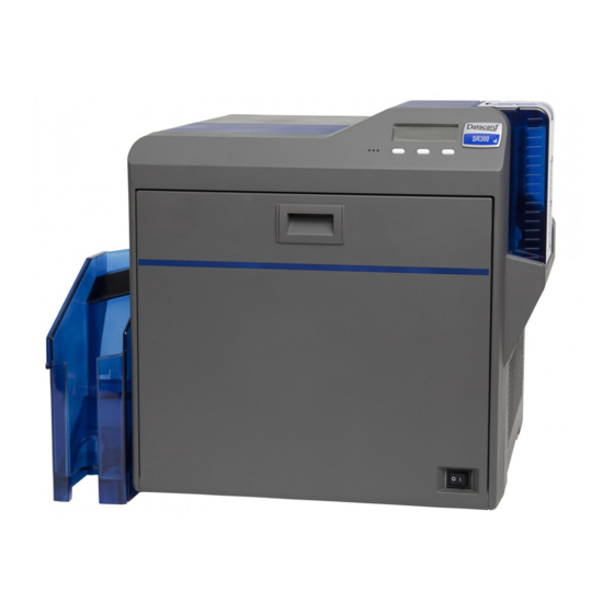
SECTION 2 SPECIFIC SERVICE INSTRUCTIONS Name and functions of parts 2.1.1 Exterior Card hopper Space for input Operation panel Card exit output connectors and buttoms Host interface Card stacker Security slot AC Inlet Printer door Cooling fan NG Card exit Communication port Power switch for laminator... - Page 7 ATTACHING THE SEPARATELY SOLD PARTS (4) Disconnect the wire connected to the MAIN Board. 2.2.1 Preparation Before connecting the separately sold parts, remove the top cov- Release the wires from the wire clamp. er and the rear cover to pull open the MAIN Board. (1) Remove the two screws attaching from the rear side of the main unit.
- Page 8 2.2.2 Attaching the reform H unit 2.2.3 Attaching the IC contact unit Note: Note: After mounting the reform H unit, be sure to check the rel- After mounting the IC contact unit, be sure to check the evant item referring to "2.3 Check details after mounting relevant item referring to "2.3 Check details after mount- separately sold parts".
- Page 9 (4) Mount the IC contact unit. (6) Connect the wire from the IC contact unit following the drawing below. View A CN1 CN3 IC Contact unit Screw : Run the wires through QYSDST2604NA x 2 this wire clamp. Slide the IC contact unit into the hook of the bracket on the main unit.
- Page 10 (7) Reattach the turn unit. 2.2.4 Attaching the MG unit Note: After mounting the MG unit, be sure to check the relevant item referring to "2.3 Check details after mounting sepa- After attaching this screw, attach rately sold parts". another two screws. Screw : QYSDST3006NA x 3 (1) Mount the MG unit.
- Page 11 (3) Close back the MAIN Board to its original position, and fix (4) Connect the wires from the MG unit and the turn unit follow- the MAIN Board with the four screws. ing the drawing below. Securely hook the two brackets, fixing the Connect the MG unit and the board bracket, and fix them with screws.
- Page 12 (2) Mount the IC R/W unit. Run the earth wire under the wires from the FRONT Board. QYSDSF3008NA x 2 IC R/W Unit QYSDST3006NA QUB340-07DMDM-E (3) Connect the wires from the IC R/W unit following the draw- ing below. Connect the supplied USB cable and the connector J1 on the MAIN Board.
- Page 13 Check details after mounting separately sold parts Item Check details Required tools Reform H unit The warpage of the printed card should be within the specs (1.5 Blank card mm). IC Contact unit Check the IC contact position mark using a blank card and a Blank card, Contact label contact label.
- Page 14 2.3.1 IC contact position adjustment Apply a contact label (part number: KXL46372-001) on the IC chip of a contact IC card. Select the IC contact test from “off line test” in the service mode to perform the test. After the test, measure the IC contact position mark on the con- tact label using a vernier caliper to check if the position stays within the specs.
-
Page 15: Section 3 Disassembly
SECTION 3 DISASSEMBLY Before disassembly, be sure to turn OFF the power and unplug (2) Slide the top cover unit to the rear side, then remove the the power cord. top cover unit. Removing the covers (See figure 1 to figure 4) Top cover unit (1) Remove the two screws A attaching the top cover unit. - Page 16 (4) Remove the two screws C attaching the side cover U-R (2) Remove the two screws D attaching the cover, then re- and side cover U-L, then remove the side cover U-R and move the cover. side cover U-L. Side cover U-R Side cover U-L Cover Head unit...
- Page 17 (4) Disconnect the two cables from the connectors on the front (7) Front panel unit with the cover removed. board. Cover Fig.10 Front panel unit Connectors (8) Disconnecting the cable from the RFID1 board detaches Fig.8 the front panel unit from the main unit. (5) Remove the one screw F attaching the cover.
- Page 18 Removing the major boards and major units (See fig- (4) Hanging the left and right brackets on the main board to the ure 13 to figure 33) hooks on the chassis prevents the main board from falling. (1) Disconnect the four cables from the connectors on the Hook main board.
- Page 19 (6) Removed CF-7MGS UNIT. (9) Remove the four screws K to release the SECURITY PWB ASSY and the solenoid on the front side. Fig.18 (7) The KEY LOCK UNIT consists of a SECURITY PWB ASSY and two solenoids. Solenoid SECURITY PWB ASSY Solenoid SECURITY PWB ASSY Fig.21...
- Page 20 (12) Removed IC R/W UNIT. (14) Remove the two screws N attaching the cover, then re- move the cover. Cover Fig.27 Fig.24 (15) Before removing the IC CON UNIT, the turn unit needs to (13) Remove the one screw M attaching the CONTACTIFC be removed first.
- Page 21 (16) Remove the four screws P attaching the turn unit from the (18) Remove the two screws Q attaching the IC CON UNIT sec- front side and the rear side. tion, then remove the IC CON UNIT section. Turn unit IC CON UNIT section Fig.29 Fig.32...
- Page 22 Replacing the head unit (See figure 34 and figure 35) Removing the reform H unit (See figure 36 and figure (1) Remove the one screw R attaching the head unit. (1) Remove the one screw S attaching the reform H unit, then pull out the reform H unit.
- Page 23 (2) Pulled out heater. (3) Remove the five screws V attaching the motor base unit, then remove the motor base unit. Heater Motor base unit Fig.39 Fig.42 Removing the motor base unit (See figure 40 to figure (4) Main unit with the motor base unit removed. (1) Push two tabs on the PS cover, then remove the PS cover.
-
Page 24: Section 4 Adjustment
SECTION 4 ADJUSTMENT This service manual does not describe ADJUSTMENT. SECTION 5 TROUBLE SHOOTING When an error message is display (2) Lift to remove the card hopper cover. When the error occurs, the error message and the error code are displayed in the operation panel. - Page 25 5.1.2 Jam (Hopper) c) Close the printer door, and press [RESET] → Card jam in the card hopper unit. Remove the jammed card. initialize the printer. Jam (Hopper) Note: • Do not apply excessive force on the card hopper. Doing so may damage it.
- Page 26 b) The cover of the card hopper is opened. When the 5.1.4 Jam (MG) card can be removed, it removes. Card jam in the magnetic encoder unit. Remove the jammed card. Jam (MG) (1) Open the printer door. (2) Restore the card to the magnetic encoder unit. (3) The turnover part is rotated a little right and left by using the Use the jog dial to turn the cleaning unit.
- Page 27 (8) Press [RESET] → to initialize the printer. (2) The retransfer film cassette (left side) is taken out, and the inside of the printer is confirmed. (3) When the card sticks on the retransfer film, the card is re- moved. (4) Close the printer door, and press [RESET] →...
- Page 28 5.1.7 Film Serch (3) Cut away the broken portion, and attach the unused por- Retransfer film is broken. Repair it. tion at the supply side to the other end at the take-up side using an adhesive tape. Film Serch Note: •...
-
Page 29: Ink Error
(6) Press [RESET] → to initialize the printer. 5.1.10 Ink Serch Ink ribbon is broken. Repair it. Ink Serch Note: • Stand the cassette on a flat surface as illustrated in the dia- gram. Avoid doing so on a floor as dust attached to the ink ribbon may cause printing errors. - Page 30 (4) Set the ink ribbon, and turn the take-up side until the cut 5.1.11 Door Open section is out of sight. Printer door is open. Close the door. Or, the cleaning roller is not • Install while referring to the indication on the label of attached.
- Page 31 (2) Press and hold down the cassette button, and pull out (6) Press [RESET] → to initialize the printer. the cassette (on the left) to remove the retransfer film. (3) Install a new retransfer film. Install while referring to the indication on the label of the cassette.
- Page 32 (1) Open the printer door. (6) Press [RESET] → to initialize the printer. (2) Press and hold down the cassette button, and pull out the cassette (on the right) to remove the ink ribbon. (3) Install a new ink ribbon. Install while referring to the indication on the label of the cassette.
- Page 33 5.1.18 HR Overheat 5.1.25 RR Thermister The temperture of the warpage correction heating roller or Warpage correction roller thermister failure. Turn off and on the retransfer heating roller is too high. Turn off and on the power. power. If the same problem recurs, turn off the power and consult If the same problem recurs, turn off the power and consult our our authorized dealers.
- Page 34 Use of service mode Besides "User mode" that is for setting this unit depending on the printing media or card used by the user, there is a "Service mode" for status checking and changing setting of this unit during service. The checking and adjustment of the following items can be per- formed in service mode: (1) Fine adjustment of the printing position (4) Information display of printer...
- Page 35 [ENTER] [ENTER] >Diag Test> >>Actuator> >>>Ink TUP Enc Ink take-up encoder [EXIT] [EXIT] [NEXT] [NEXT] [NEXT] >>>Ink TUP Mo Ink take-up motor [NEXT] >>>Ink SPY Mo Ink supply motor [NEXT] >>>Film TUP Mo Film take-up motor [NEXT] >>>Film SPY Mo Film supply motor [NEXT] >>>Card Feed Mo...
- Page 36 >Push Parameter settings save in the head EEP-ROM. * The buzzer beeps in case of an error. [NEXT] Loading the parameter settings from the head EEP-ROM. >Pop * If the correct data is not stored by the head EEP-ROM, "No Data" is displayed and the buzzer beeps. [NEXT] [ENTER] [ENTER]...
-
Page 37: Wiring Diagram
Wiring diagram 1-36 (No.HD007<Rev.001>) -
Page 38: Block Diagram
Block diagram (No.HD007<Rev.001>)1-37... -
Page 39: Troubleshooting Sheet
Troubleshooting Sheet Rev. 1.0 Customer Details Device Info. Company Department Model Printer In-charge Serial No. Printer Note 1) In-charge Purchase date Printer Details of Trouble (Multiple entries allowed) Frequency of Occurrence (Multiple entries allowed) Timing of Occurrence (Multiple entries allowed) A: Does not switch to the Ready mode.
Need help?
Do you have a question about the SR200 and is the answer not in the manual?
Questions and answers