
Related Manuals for Falcon Professional + FX


Summary of Contents for Falcon Professional + FX
-
Page 1: User Guide
� ������������ �� ArtNo.000-0025 - Professional + FX logo Dual Fuel User Guide & Installation & Service Instructions ArtNo.000-0008 Falcon logo shaded U110008 - 01 Australia... -
Page 2: Table Of Contents
Contents Before You Start... Installation Installation and Maintenance Service and Spares Peculiar Smells Dear Installer If you smell gas: Provision of Ventilation Ventilation Location of Cooker Personal Safety Conversion Cleaning Positioning the Cooker Moving the Cooker Overview Completing the Move Hotplate Burners Levelling Wok Burner... -
Page 3: Before You Start
1. Before You Start... Ventilation Thank you for buying a Falcon cooker. It should give you many years of trouble-free cooking if installed and operated The use of a gas cooking appliance results in the production correctly. It is important that you read this section before of heat and moisture in the room in which it is installed. -
Page 4: Cleaning
Cleaning Use dry oven gloves when applicable – using damp gloves might result in steam burns when you touch a hot surface. In the interests of hygiene and safety, the cooker should be Do not use a towel or other bulky cloth in place of a glove – it kept clean at all times as a build up in fats and other food might catch fire if brought into contact with a hot surface. -
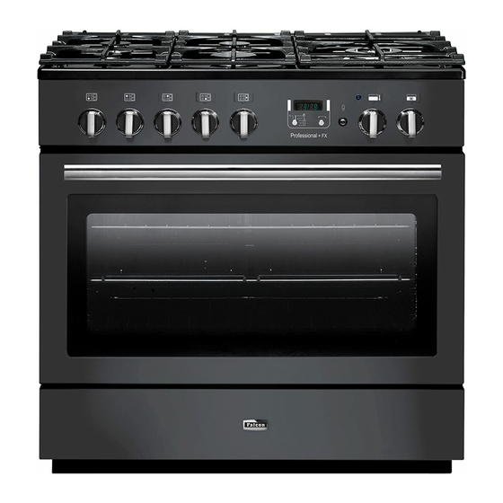
Page 5: Overview
2. Overview DocNo.025-0101 - Overview - 90 DF SC - Prof+ FX Fig.2-1 � � Professional + FX � � ArtNo.270-0029 - Prof+ 90SC annotated The dual fuel single cavity cooker (Fig.2-1) has the following Fig.2-2 features: ArtNo.270-0001 Proplus control to high 5 hotplate burners including a wok burner A control panel incorporating a timer A multi-function oven... -
Page 6: Wok Burner
If, when you let go of the control knob, the burner goes out, Fig.2-3 then the FSD has not been bypassed. Turn the control knob ArtNo.270-0003 Proplus control to low to the OFF position and wait for one minute before you try again, this time making sure to hold in the control knob for slightly longer. -
Page 7: The Griddle
The cradle will get very hot in use – allow plenty of time for it Fig.2-10 to cool before you pick it up. The Griddle The griddle fits the left-hand well, front to back (Fig.2-11). It is designed for cooking food on directly. DO NOT use pans of any kind on it. - Page 8 Multi-function oven modes (Fig.2-13) Fig.2-13 ArtNo.270-0025 Defrost Proplus MF oven annotated � � This function operates the fan(s) to circulate cold air ArtNo.030-0028 - Elan MF symbols only. No heat is applied. This enables small items such as desserts, cream cakes and pieces of meat, fish and poultry to be defrosted.
-
Page 9: Energy Saving Feature
Conventional Oven (Top and Base Heat) This function combines the heat from the top and WARNING! Elan MF symbols base elements. It is particularly suitable for roasting Take great care when removing the divider NOT to and baking pastry, cakes and biscuits. scratch the inner glass door surface. -
Page 10: Operating The Oven
DO NOT place or slide metallic objects, including cookware, Fig.2-17 on the door glass as this may cause scratching and subsequent failure to occur. ArtNo.270-0026 Proplus MF oven controls (2) Operating the Oven The multi-function oven has two controls: a function selector and a temperature setting knob (Fig.2-17). -
Page 11: Manual Cooking
Once the ‘stop time’ is reached, the beeper sounds. Turn the Fig.2-26 Fig.2-25 Timer knob to the vertical ( ) to return to manual cooking. ArtNo.301-0010 2BC ArtNo.301-0009 2BC To start and then stop the oven using the Timer Setting the cooking time Setting the cooking timer You cannot set a start time directly –... -
Page 12: Accessories
Fig.2-34 Oven racks Each oven is supplied with: ArtNo.326-0013 - Full capacity shelf Two full capacity shelves (Fig.2-33) (Falcon) ArtNo.326-0004 - Cradle shelf Grill pan tray support (Fig.2-34) Two grill pans with trivets (Fig.2-35) Three energy saving shelves (Fig.2-36) Fig.2-35 Fig.2-36... -
Page 13: Storage
Storage Fig.2-42 The bottom drawer is for storing oven trays and other cooking utensils. It can get very warm, so do not store anything in it that may melt or catch fire. Never store flammable materials in the drawer. This includes paper, plastic and cloth items, such as cookbooks, plastic ware and towels, as well as flammable ArtNo.281-0138 - Drawer pulled out liquids. -
Page 14: Cooking Tips
3. Cooking Tips Cooking with a Multi-function Oven Remember: not all modes are suitable for all food types. The oven cooking times given are intended for a guide only. General Oven Tips The wire shelves should always be pushed firmly to the back of the oven. -
Page 15: Cooking Table
4. Cooking Table DocNo.031-0004 - Cooking table - electric & fan single cavity The oven control settings and cooking times given in the table below are intended to be used AS A GUIDE ONLY. Individual tastes may require the temperature to be altered to provide a preferred result. -
Page 16: Troubleshooting
5. Troubleshooting Steam is coming from the oven If two racks are used, check that space has been left for the heat to circulate. When a baking sheet is put into the When cooking foods with a high water content (e.g. oven, make sure it is placed centrally on the rack. - Page 17 Hotplate ignition or cooktop burners faulty Fig.5-1 Is the power on? Are the sparker (ignition electrode) or burner holes blocked by debris? ArtNo.324-0005 Oven light bulb Are the burner heads correctly located? See the section entitled ‘Cleaning’ . Remember that each cooktop burner has a special safety device that stops the flow of gas if the flame goes out.
-
Page 18: Cleaning Your Cooker
6. Cleaning Your Cooker Isolate the electricity supply before carrying out any major Fig.6-1 cleaning. Allow the cooker to cool. � Never use paint solvents, washing soda, caustic cleaners, biological powders, bleach, chlorine based bleach cleaners, coarse abrasives or salt. Do not mix different �... -
Page 19: Hotplate Burners
Hotplate Burners Fig.6-2 ArtNo.311-0014 Wok burner details � The burner heads and caps can be removed for cleaning. Make sure they are absolutely dry before replacing. The Single Ring Burners � When refitting the burner head, ensure that the notch lines up with the electrode or hole in the base. -
Page 20: Cleaning Table
Cleaning Table Cleaners listed are available from supermarkets or electrical retailers as stated. Cleaner manufacturer in Italics. For enamelled surfaces use a cleaner that is approved for use on vitreous enamel. Regular cleaning is recommended. For easier cleaning, wipe up any spillages immediately. To help keep your oven clean, cover meat when roasting, with foil or use a roasting bag. -
Page 21: Installation
INSTALLATION Check the appliance is electrically safe and gas sound when you have finished. 7. Installation Service and Spares Firstly, please complete the appliance details below and keep them safe for future reference – this information will enable us to accurately identify the particular appliance and help us to help you. Filling this in now will save time and inconvenience if you later have a problem with the appliance. -
Page 22: Dear Installer
INSTALLATION Check the appliance is electrically safe and gas sound when you have finished. Dear Installer Provision of Ventilation Before you start your installation, please complete the details This appliance is not connected to a combustion products below, so that, if your customer has a problem relating to evacuation device. - Page 23 flexible hose, a restraining chain must be fitted. ArtNo.000-0002 Classic tools ArtNo.326-0013 - Full capacity shelf • Flexible gas hose. (Falcon) • Gas pressure tester/manometer • Multimeter: For electrical checks Grill pan tray support 2 grill pans & trivets...
-
Page 24: Positioning The Cooker
INSTALLATION Check the appliance is electrically safe and gas sound when you have finished. Positioning the Cooker Fig.7-1 The diagram (Fig.7-1) shows the minimum recommended distance from the cooker to nearby surfaces as given in AS 5601. Overhead – Measurement A The minimum height of any surface above the cooker is �... -
Page 25: Completing The Move
INSTALLATION Check the appliance is electrically safe and gas sound when you have finished. Removing the Storage Drawer Fig.7-2 Pull the drawer out to its furthest point (Fig.7-2). Lift up the ends of the plastic clips (one each side) to release the catches holding the drawer to the side runners and at the same time pull the drawer forward and away from the side runners (Fig.7-3). -
Page 26: Stability Bracket And Chain
INSTALLATION Check the appliance is electrically safe and gas sound when you have finished. Stability Bracket and Chain Fig.7-7 A stability bracket and chain should be fitted when � � the cooker is connected to a flexible gas supply. �... -
Page 27: Gas Connection
INSTALLATION Check the appliance is electrically safe and gas sound when you have finished. Gas Connection Fig.7-12 Must be in accordance with the relevant standards. �� �� The gas supply needs to terminate with a down facing bayonet. ��� Because the height of the cooker can be adjusted and each connection is different it is difficult to give precise ���... -
Page 28: Electrical Connection
INSTALLATION Check the appliance is electrically safe and gas sound when you have finished. Electrical Connection Fig.7-13 This appliance must be installed by a qualified electrician to comply with the relevant regulations (AS/NZS 60335.2.6:2002) and also the local electricity supply company requirements. -
Page 29: Fitting The Plinth
INSTALLATION Check the appliance is electrically safe and gas sound when you have finished. Oven Check Fig.7-17 Turn on the oven and check that it starts to heat up. Check that the oven lights are working. Note: The oven light bulb is not included in the guarantee. Turn off... -
Page 30: Conversion To Propane Gas
WARNING – SERVICING TO BE CARRIED OUT ONLY BY AN AUTHORISED PERSON Disconnect from electricity and gas before servicing. Check appliance is safe when you have finished. 8. Conversion to Propane Gas DocNo.071-0003 - LP gas conversion - 90 single cavity Check in the ‘Technical Data’... -
Page 31: Set The Governor
WARNING – SERVICING TO BE CARRIED OUT ONLY BY AN AUTHORISED PERSON Disconnect from electricity and gas before servicing. Check appliance is safe when you have finished. Set the Governor Fig.8-5 Unscrew the governor’s brass top. In the base of the brass top is a plastic snap-in converter device (Fig.8-5). -
Page 32: Servicing
WARNING – SERVICING TO BE CARRIED OUT ONLY BY AN AUTHORISED PERSON Disconnect from electricity and gas before servicing. Check appliance is safe when you have finished. 9. Servicing BEFORE SERVICING ANY GAS CARRYING Fig.9-1 COMPONENTS. TURN OFF THE GAS SUPPLY DO NOT modify this appliance! Check the appliance is gas sound after completion of service. - Page 33 WARNING – SERVICING TO BE CARRIED OUT ONLY BY AN AUTHORISED PERSON Disconnect from electricity and gas before servicing. Check appliance is safe when you have finished. To Change Oven or Light Switch Fit the replacement in reverse order. Ensure the phial is clipped securely to the oven rear cover. Disconnect the cooker from the electricity supply.
- Page 34 WARNING – SERVICING TO BE CARRIED OUT ONLY BY AN AUTHORISED PERSON Disconnect from electricity and gas before servicing. Check appliance is safe when you have finished. 11. To Remove a Hotplate Burner Thermocouple Fig.9-5 Disconnect the cooker from the electricity supply. Remove the hotplate (see 2).
- Page 35 WARNING – SERVICING TO BE CARRIED OUT ONLY BY AN AUTHORISED PERSON Disconnect from electricity and gas before servicing. Check appliance is safe when you have finished. Lift out the inner panel and place it, outer side up, on a clean Fig.9-8 level surface.
- Page 36 WARNING – SERVICING TO BE CARRIED OUT ONLY BY AN AUTHORISED PERSON Disconnect from electricity and gas before servicing. Check appliance is safe when you have finished. 21. To Remove the Oven Bottom and Top Elements Fig.9-12 Disconnect the cooker from the electricity supply. Bottom Element Pull the cooker forward to access the cover boxes at the rear of �...
-
Page 37: Circuit Diagram
10. Circuit Diagram... -
Page 38: Technical Data
11. Technical Data This cooker is designed for use on natural gas but can be converted to LP (Propane X (2.54kPa). A conversion kit from Natural Gas to Propane is supplied with the cooker. Installer: Please leave these instructions with the user. DATA BADGE LOCATION: Inside base drawer of cavity and on rear of the appliance.
Need help?
Do you have a question about the Professional + FX and is the answer not in the manual?
Questions and answers