
Related Manuals for Falcon Kitchener


Summary of Contents for Falcon Kitchener
- Page 1 USER GUIDE & INSTALLATION INSTRUCTIONS Kitchener & Professional + 90 Dual Fuel Australia U110138-07A...
- Page 2 SLOW BAKED LEG OF LAMB METHOD Preheat the oven to 220 °C (for a conventional oven), 200 °C (for a fan oven) or gas mark 7. Pull the small sprigs off the rosemary branches and set aside with the garlic. Using the tip of a paring knife, make up to 20 well-spaced cuts into the flesh of the lamb, about 2.5 cm inch deep.
-
Page 3: Table Of Contents
Cleaning Your Cooker Tap Adjustment Essential Information Set the Governor Hotplate Burners Pressure Testing Grills Affix Label Control Panel and Doors Servicing Ovens 10. Circuit Diagram The Tall Oven Cleaning Table 11. Technical Data Kitchener and Professional+ 90 Dual Fuel... -
Page 5: If You Smell Gas
Before You Start... • DO NOT use a steam cleaner on your cooker. Your cooker should give you many years of trouble-free cooking if installed and operated correctly. It is important • Always keep combustible materials, e.g. curtains, and that you read this section before you start. flammable liquids a safe distance away from the cooker. - Page 6 Peculiar Smells Maintenance • Only a qualified service engineer should service the When you first use your cooker it may give off an odour. This should stop after use. appliance and only approved spare parts should be used. It is recommended that this appliance is serviced Before using for the first time, make sure that all packing annually.
-
Page 7: Before You Start
a flaming pan on a surface unit by covering the pan Fig. 1.1 completely with a well fitting lid or baking tray. If available, use a multi-purpose dry chemical or foam- type fire extinguisher. • DO NOT modify this appliance. This appliance is not intended to be operated by means of external timer or separated remote-control system. -
Page 8: Cleaning
Grill/Glide-out Grill™ Care Cleaning • When using the grill, make sure that the grill pan is • Isolate the electricity supply before carrying out any in position and pushed fully in, otherwise the control thorough cleaning. Allow the cooker to cool. knobs may become very hot. -
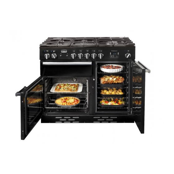
Page 9: Cooker Overview
2. Cooker Overview DocNo.020-0006 - Overview - 90DF - Prof+ Fig. 2.1 The 90 dual fuel cooker (Fig. 2.1) has the following features: Fig. 2.2 ArtNo.270-0001 5 hotplate burners including a wok burner Proplus control to high A control panel A glide-out grill Programmable main fan oven Tall fan oven... -
Page 10: Wok Burner
If, when you let go of the control knob, the burner goes out, Fig. 2.3 then the FSD has not been bypassed. Turn the control knob ArtNo.270-0003 to the OFF position and wait for one minute before you try Proplus control to low again, this time making sure to hold in the control knob for slightly longer. -
Page 11: The Wok Cradle (Optional)
The Wok Cradle (optional) Fig. 2.9 The wok cradle is designed to fit a 35 cm wok. If you use a different wok, make sure that it fits the cradle. Woks vary very widely in size and shape. It is important that the wok sits down on the pan support –... -
Page 12: The Grill / Glide-Out Grill
The Grill / Glide-out Grill Fig. 2.15 CAUTION: This appliance is for cooking purposes only. It must not be used for other purposes, for example room heating. ArtNo.330-0003 - Grill pan w handle pulled forwards CAUTION: Accessible parts may be hot when the grill is in use. -
Page 13: The Ovens
The Ovens Fig. 2.19 The clock must be set to the time of day before the left- ArtNo.270-0005 Proplus electric oven control hand oven will work. See the following section on ‘The Clock’ for instructions on setting the time of day. References to ‘left-hand’... -
Page 14: Accessories
Accessories Fig. 2.21 Shelf guard Oven Shelves – Left-hand (Main) Oven The oven shelves (Fig. 2.21) are retained when pulled forward but can be easily removed and refitted. Pull the shelf forward until the back of the shelf is stopped by the shelf stop bumps in the oven sides (Fig. -
Page 15: The Clock
3. The clock The clock must be set to the time of day before the oven Fig. 3.1 ArtNo.300-0005 2BC will work. minute minder setting The 2-button clock Setting the Clock Once the cooker is connected and switched on, the display will start to flash. - Page 16 To stop the oven at a specific time of day Fig. 3.5 You have set the required temperature and function mode and you would like the oven to automatically stop. TOP TIP Make a note of the current time so you do not forget. Turn the Timer (A) knob to the Stop Time (G) setting.
- Page 17 To start and stop the oven automatically Fig. 3.9 The timer allows you to automatically start and stop by a combination of the length of the cooking time and the stop time. Giving you the flexibility to cook casseroles etc while you are out.
-
Page 18: Setting The Time Of Day
The 6-button clock Fig. 3.17 You can use the timer (Fig. 3.17) to turn the oven(s) on and off. The clock must be set to the time of day before the oven(s) will work. Table 3.1 describes the symbols shown on the digital display. ArtNo.302-0002 - 6BC annotated Setting the time of day When the cooker is first connected to the mains, or if there... - Page 19 then press any button to stop the beep. Press [ ] to return to Fig. 3.23 Fig. 3.24 manual cooking. Setting a cook end time ] button (Fig. 3.23) and then Press and hold the ‘stop time’ [ press the [+] button (or [–] button) until the required ‘stop ArtNo.302-0002 - 6BC annotated ArtNo.302-0002 - 6BC annotated...
-
Page 20: Cooking Tips
Cooking tips Tips on cooking with the timer General oven tips If you want to cook more than one dish, choose dishes that The wire shelves should always be pushed firmly to the back require approximately the same cooking time. However, of the oven. -
Page 21: Cooking Table
Cooking table DocNo.031-0004 - Cooking table - electric & fan single cavity The oven control settings and cooking times given in the table below are intended to be used Top (T) AS A GUIDE ONLY. Individual tastes may require the temperature to be altered to provide a preferred result. -
Page 22: Cleaning Your Cooker
ArtNo.045-0004 - Cleaning - 90 induction - tpl glzd dr & GO grill 5. Cleaning Your Cooker Essential Information Fig. 5.1 Isolate the electricity supply before carrying out any thorough cleaning. Allow the cooker to cool. NEVER use paint solvents, washing soda, caustic cleaners, biological powders, bleach, chlorine based bleach cleaners, coarse abrasives or salt. -
Page 23: Grills
Grills Fig. 5.1 The grill pan and trivet should be washed in hot soapy water. Alternatively, the grill pan can be washed in a dishwasher. After grilling meats or any foods that soil, leave to soak for a few minutes immediately after use. Stubborn particles may be removed from the trivet using a nylon brush. -
Page 24: Ovens
Glass Fronted Door Panels Fig. 5.1 The oven door front panels can be taken off so that the glass panels can be cleaned. Move the cooker forward to gain access to the sides (see the ‘Moving the Cooker’ section under ‘Installation’). -
Page 25: Cleaning Table
Cleaning Table Cleaners listed (Table 5-1) are available from supermarkets or electrical retailers as stated. For enamelled surfaces use a cleaner that is approved for use on vitreous enamel. Regular cleaning is recommended. For easier cleaning, wipe up any spillages immediately. Hotplate Part Finish... -
Page 26: Troubleshooting
6. Troubleshooting Hotplate ignition or hotplate burners faulty Power failure Is the power on? Is the clock illuminated? In the event of a failure in the electrical supply, remember to reset the clock to make sure that the If not, there maybe something wrong with the power timed oven continues to operate. - Page 27 An oven light is not working Fig. 6.1 The bulb has probably burnt out. You can buy a replacement bulb (which is not covered under the warranty) from a good electrical shop. Ask for a 15 W – 230 V lamp, FOR OVENS. It must be a special bulb, heat ArtNo.324-0005 Oven light bulb resistant to 300 °C (Fig.
-
Page 28: Installation
INSTALLATION Check the appliance is electrically safe and gas sound when you have finished. 7. Installation Service and Spares Firstly, please complete the appliance details below and keep them safe for future reference – this information will enable us to accurately identify the particular appliance and help us to help you. Filling this in now will save time and inconvenience if you later have a problem with the appliance. -
Page 29: Safety Requirements And Regulations
INSTALLATION Check the appliance is electrically safe and gas sound when you have finished. Safety Requirements and Regulations Provision of Ventilation Please read the Before you start... chapter, before This appliance is not connected to a combustion products you begin any installation and maintenance work on evacuation device. - Page 30 INSTALLATION Check the appliance is electrically safe and gas sound when you have finished. You will need the following equipment to complete the Checking the Parts: cooker installation satisfactorily: 3 pan supports Plinth (1-piece model shown) • Flexible gas hose. •...
-
Page 31: Positioning The Cooker
70°C. If this appliance is installed near vinyl wrapped surfaces, use an installation kit available from the vinyl-wrap supplier. Falcon cannot accept any responsibility for damage caused due to installation into cabinets with low temperature tolerances. -
Page 32: Completing The Move
INSTALLATION Check the appliance is electrically safe and gas sound when you have finished. Moving the Cooker Fig. 7.4 On no account try and move the cooker while it is plugged into the electricity supply. The cooker is very heavy, so take great care. We recommend two people manoeuvre the cooker. -
Page 33: Gas Connection
INSTALLATION Check the appliance is electrically safe and gas sound when you have finished. Fitting a Stability Bracket Fig. 7.9 When fitting a stability bracket please refer to the instructions supplied with the bracket for further details on fitting. When fitting a stability bracket (Fig. 7.7 and Fig. 7.8) adjust Restraining the bracket to give the smallest practicable clearance chain... -
Page 34: Pressure Testing
INSTALLATION Check the appliance is electrically safe and gas sound when you have finished. Pressure Testing Fig. 7.11 The pressure test point is accessible on the inlet pipe at the rear. Remove the test nipple screw and fit a pressure gauge to the test point. -
Page 35: Final Checks
Note: The clock must be set before the ovens will work. See ‘The Clock’ section for instructions on setting the time of day. ArtNo.350-0010 - Fitting the plinth 1 (Kitchener) Hotplate Check Check each burner in turn. There is a Flame Supervision Device (FSD) that stops the flow of gas to the burner if the flame goes out. -
Page 36: Conversion To Propane Gas
WARNING – SERVICING TO BE CARRIED OUT ONLY BY AN AUTHORISED PERSON Disconnect from electricity and gas before servicing. Check appliance is safe when you have finished. 8. Conversion to Propane Gas Conversion from Natural Gas (1.0 kPa) Fig. 8.1 to LPG X Propane (2.54 kPa) This conversion must be performed by a competent person, in accordance with these instructions and... -
Page 37: Set The Governor
WARNING – SERVICING TO BE CARRIED OUT ONLY BY AN AUTHORISED PERSON Disconnect from electricity and gas before servicing. Check appliance is safe when you have finished. Set the Governor Fig. 8.4 Unscrew the governor’s brass top. In the base of the brass top is a plastic snap-in converter device (Fig. -
Page 38: Servicing
WARNING – SERVICING TO BE CARRIED OUT ONLY BY AN AUTHORISED PERSON Disconnect from electricity before servicing. Check appliance is safe when you have finished. 9. Servicing BEFORE SERVICING ANY GAS CARRYING Fig. 9.1 COMPONENTS TURN OFF THE GAS SUPPLY Check the appliance is gas sound after completion of service. - Page 39 WARNING – SERVICING TO BE CARRIED OUT ONLY BY AN AUTHORISED PERSON Disconnect from electricity before servicing. Check appliance is safe when you have finished. 2 Hotplate The burners are fixed to the support struts with 2 screws. Remove the appropriate burner and fit the new 2.1 To Remove the Hotplate one.
- Page 40 WARNING – SERVICING TO BE CARRIED OUT ONLY BY AN AUTHORISED PERSON Disconnect from electricity before servicing. Check appliance is safe when you have finished. 3.3 To Change the Ignition Generator Fig. 9.3 DISCONNECT FROM THE ELECTRICITY SUPPLY. Pull the cooker forwards to gain access to the cover box at the rear of the cooker.
- Page 41 WARNING – SERVICING TO BE CARRIED OUT ONLY BY AN AUTHORISED PERSON Disconnect from electricity before servicing. Check appliance is safe when you have finished. 5.2 To Change the Oven Fan Fig. 9.4 DISCONNECT FROM THE ELECTRICITY SUPPLY. Pull the cooker forward to gain access to the rear. Remove the screws securing the electric cover to the back sheet and remove the cover.
- Page 42 WARNING – SERVICING TO BE CARRIED OUT ONLY BY AN AUTHORISED PERSON Disconnect from electricity before servicing. Check appliance is safe when you have finished. For either oven, feed the thermostat capillary out of Fig. 9.6 Fig. 9.7 the oven. Disconnect the wiring from the thermostat. Remove the 2 screws holding the thermostat to the mounting panel.
- Page 43 WARNING – SERVICING TO BE CARRIED OUT ONLY BY AN AUTHORISED PERSON Disconnect from electricity before servicing. Check appliance is safe when you have finished. 6.6 To Change the Main Oven Door Latch Fig. 9.11 Fig. 9.12 Remove the outer door panel (see 6.5). Remove screws ‘B’...
-
Page 44: Circuit Diagram
10. Circuit Diagram P095199 P095199 br br The connections shown in the circuit diagram are for single-phase. The ratings are for 230 V 50 Hz. Code Description Code Description Code Colour Grill control Oven lamp Blue Brown Grill element right-hand side Ignition switch Grill element left-hand side Ignition spark generator... -
Page 45: Technical Data
11. Technical Data DocAUS.102-0002 - Technical data - 90DF - Prof+ This cooker is designed for use on Natural Gas, although a conversion for LP (LPG X Propane (2.54 kPa) gas is packed with the cooker. INSTALLER: Please leave these instructions with the user. DATA BADGE LOCATION: Cooker back. - Page 46 Clarence Street, Royal Leamington Spa, Warwickshire, CV31 2AD, England. Tel: +44 (0) 800 804 6261 | +44 (0) 370 789 5107 E-mail: consumers@falconappliances.co.uk...
Need help?
Do you have a question about the Kitchener and is the answer not in the manual?
Questions and answers