Table of Contents
Advertisement
Quick Links
Advertisement
Table of Contents

Related Manuals for Falcon Professional+ 100FX Dual Fuel


Summary of Contents for Falcon Professional+ 100FX Dual Fuel
- Page 1 USER GUIDE & INSTALLATION INSTRUCTIONS Professional+ 100 FX Dual Fuel U111301-01...
-
Page 3: Table Of Contents
Contents Before you start... Service and Spares Personal safety Installation Electrical Connection Safety Safety Requirements and Regulations If you smell gas Provision of Ventilation Peculiar smells Location of Cooker Cooling fan Conversion Ventilation Positioning the Cooker Maintenance Moving the Cooker Cooker care Completing the Move Cleaning... -
Page 5: Before You Start
Before you start... Your cooker should give you many years of The cooker should not be placed on a base. • trouble-free cooking if installed and operated This appliance is designed for domestic • correctly. It is important that you read this cooking only. -
Page 6: Electrical Connection Safety
Always keep combustible materials, e.g. Make sure that the gas supply is turned • • curtains, and flammable liquids a safe on and that the cooker is wired in and distance away from the cooker. switched on. DO NOT spray aerosols in the vicinity of In your own interest and that of safety, it is •... -
Page 7: Ventilation
NEVER leave the hotplate unattended Ventilation • at high heat settings. Pans boiling over The use of a cooking appliance results in the can cause smoking, and greasy spills may production of heat and moisture in the room catch on fire. Use a deep fat thermometer in which it is installed. - Page 8 DO NOT modify this appliance. This • Fig. 1.1 appliance is not intended to be operated by means of external timer or separated remote-control system. If flammable materials are stored in the • drawer, oven(s) or grill(s) it may explode and result in fire or property damage.
-
Page 9: Cooker Care
DO NOT use the timed oven if the Cleaning • adjoining oven is already warm. Isolate the electricity supply before • DO NOT place warm food in the oven to carrying out any thorough cleaning. Allow • be timed. the cooker to cool. DO NOT use a timed oven that is already In the interests of hygiene and safety, the •... - Page 10 NEVER store flammable materials in the • drawer. This includes paper, plastic and cloth items, such as cookbooks, plastic ware and towels, as well as flammable liquids. DO NOT store explosives, such as aerosol • cans, on or near the appliance. DO NOT use steel wool, oven cleaning •...
-
Page 11: Cooker Overview
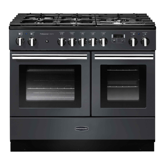
Cooker Overview Fig. 2.1 Professional + 100 FX ArtNo.270-0029 - Prof+ 90SC annotated The 100 dual fuel cooker (Fig. 2.1) has the following features: Fig. 2.2 ArtNo.270-0001 A. 5 hotplate burners including a wok burner Proplus control to high B. A control panel incorporating a timer C. -
Page 12: Wok Burner
If, when you let go of the control knob, the burner goes out, Fig. 2.3 then the FSD has not been bypassed. Turn the control knob ArtNo.270-0003 to the ‘OFF’ position and wait for one minute before you try Proplus control to low again, this time making sure to hold in the control knob for slightly longer. -
Page 13: The Griddle Plate
The Griddle Plate Fig. 2.11 The griddle plate fits the left-hand pan support, front to back (Fig. 2.11). It is designed for cooking food on directly. DO NOT use pans of any kind on it. The griddle plate surface is non-stick and metal cooking utensils (e.g. spatulas) will damage the surface. -
Page 14: The Multifunction Ovens
Left-hand Multifunction Oven Modes The Multifunction Ovens Function Both ovens are multifunction ovens. Defrost In addition to the element around the fan, the left-hand oven To thaw small items in the oven without heat is fitted with extra heating elements, in the top of the oven A full cooking function, even heat throughout, and under the oven base. - Page 15 Fanned Grilling Right-hand Multifunction Oven Modes This function operates the fan while the top element Table 2.2 gives a summary of the right-hand multi-function is on. It produces a more even, less fierce heat than a modes. The multi-function oven has many varied uses. We conventional grill.
-
Page 16: The Ovens
The Ovens Fig. 2.15 The clock must be set to the time of day before the left-hand oven will work. See the following section on ‘The Clock’ for instructions on setting the time of day. The clock only ArtNo.270-0026 Proplus MF oven controls (2) controls the left-hand oven. -
Page 17: Accessories
Accessories Fig. 2.17 Oven Shelves – Left-hand (Main) Oven The left-hand oven is supplied with two flat shelves (Fig. 2.17). The oven shelves are retained when pulled forward but can be easily removed and refitted. To refit the shelf, line up the shelf with a groove in the oven shelf supports and push the shelf back until the ends hit the shelf stop. -
Page 18: Rotary Clock
3. Rotary clock To stop the oven at a specific time of day Symbol key (main oven only) You have set the required temperature and function mode and you would like the oven to automatically stop. manual clock Step. 1 Note: The cook minute minder symbol [ ] remains... - Page 19 To start and stop the oven automatically (main oven only) The timer allows you to automatically start and stop by a combination of the length of the cooking time and the stop time. Giving you the flexibility to cook casseroles etc while you are out. You cannot set the actual start time. Step.
-
Page 20: Cooking Tips
Cooking Tips Cooking with a Multifunction Oven General Oven Tips Remember: not all modes are suitable for all food types. The The wire shelves should always be pushed firmly to the back oven cooking times given are intended for a guide only. of the oven. -
Page 21: Cooking Table
Cooking Table The oven control settings and cooking times given in the table below are intended to be USED Top (T) AS A GUIDE only. Individual tastes may require the temperature to be altered to provide a preferred result. Food is cooked at lower temperature in a fan oven than in a conventional oven. ArtNo.050-0007 Centre (C) Oven shelf positions... -
Page 22: Cleaning Your Cooker
Cleaning Your Cooker Essential Information Fig. 6.1 Isolate the electricity supply before carrying out any thorough cleaning. Allow the cooker to cool. Never use paint solvents, washing soda, caustic cleaners, biological powders, bleach, chlorine based bleach cleaners, coarse abrasives or salt. Do not mix different cleaning products –... -
Page 23: Control Panel And Doors
Control Panel and Doors Fig. 6.5 Avoid using any abrasive cleaners including cream cleaners. For best results, use a liquid detergent. The same cleaner can be used on the doors, or alternatively, using a soft cloth wrung out in clean hot soapy water – but take care that no surplus water seeps into the appliance. -
Page 24: Cleaning Table
Cleaning Table Cleaners listed (Table 6.1) are available from supermarkets or electrical retailers as stated. For enamelled surfaces use a cleaner that is approved for use on vitreous enamel. Regular cleaning is recommended. For easier cleaning, wipe up any spillages immediately. Hotplate Part Finish... -
Page 25: Troubleshooting
Troubleshooting Hotplate ignition or hotplate burners faulty If there is an installation problem and I don’t get my original installer to come back to fix it who pays? Is the power on? Is the clock illuminated? You do. Service organisations will charge for their call outs if If not, there maybe something wrong with the power supply. - Page 26 The timed oven is not coming on when automatic Fig. 7.1 Fig. 7.2 cooking Has the oven knob been left in the OFF position by mistake? Oven temperature getting hotter as the cooker gets older If turning the temperature down using the oven control knob has not worked, or has only worked for a short time, then you may need a new thermostat.
-
Page 27: Service And Spares
INSTALLATION Check the appliance is electrically safe when you have finished. Service and Spares Firstly, please complete the appliance details below and keep them safe for future reference – this information will enable us to accurately identify the particular appliance and help us to help you. Filling this in now will save time and inconvenience if you later have a problem with the appliance. -
Page 28: Installation
INSTALLATION Check the appliance is electrically safe and gas sound when you have finished. Installation Safety Requirements and Provision of Ventilation Regulations This appliance is not connected to a combustion products evacuation device. Particular attention shall be given to the You must be aware of the following safety requirements &... - Page 29 10. Screws for fitting the stability bracket ArtNo.331-0008 - 90SC 11. 4 mm & 3 mm Allen keys grill pan & trivet ArtNo.326-0015 - Energy saving shelf (Falcon) 12. 13 mm spanner or socket wrench Restraining chain & hook Magnetic plinth ArtNo.020-0021 - Restraining...
-
Page 30: Positioning The Cooker
70°C. If this appliance is installed near vinyl wrapped surfaces, use an installation kit available from the vinyl-wrap supplier. Falcon cannot accept any responsibility for damage caused due to installation into cabinets with low temperature tolerances. -
Page 31: Moving The Cooker
INSTALLATION Check the appliance is electrically safe and gas sound when you have finished. Moving the Cooker Fig. 9.2 On no account try and move the cooker while it is plugged into the electricity supply. The cooker is very heavy, so take great care. We recommend that two people manoeuvre the cooker. -
Page 32: Fitting The Stability Bracket And Chain
INSTALLATION Check the appliance is electrically safe and gas sound when you have finished. To set the front turn the feet bases to raise or lower. Fig. 9.6 Fitting the Stability Bracket and Chain A stability bracket and chain MUST be fitted when Alternative positions the cooker is connected to a flexible gas supply. -
Page 33: Conversion To Another Gas
INSTALLATION Check the appliance is electrically safe and gas sound when you have finished. When you replace the cooker, again check behind to make Fig. 9.10 sure that the electricity cable and gas hose are not caught or Pipework Pipework trapped. -
Page 34: Electrical Connection
INSTALLATION Check the appliance is electrically safe and gas sound when you have finished. Electrical Connection Current Operated Earth Leakage Breakers This appliance must be installed by a qualified electrician The combined use of your cooker and other domestic to comply with with current AS/NZS 3000 Wiring Rules and appliances may cause nuisance tripping, so we recommend regulations in force. -
Page 35: Connection In New Zealand
INSTALLATION Check the appliance is electrically safe and gas sound when you have finished. Connection in New Zealand Fig. 9.14 Type of cord in accordance with IEC 60227 with a minimum rating of 90°C. Cord size recommended for this application is 3 x 10 mm², three-core cable (Power cables may be sized to take into account the coincidence factor AS/NZS 60335.2.6:2014). -
Page 36: Final Checks
INSTALLATION Check the appliance is electrically safe and gas sound when you have finished. Final Checks Fig. 9.19 Hotplate Check Check each burner in turn (refer to the ‘Hotplate Burners’ section at the front of the instructions). Oven Check Set the clock as described earlier in the instructions, and then turn on the ovens. -
Page 37: Fitting The Drawer
INSTALLATION Check the appliance is electrically safe and gas sound when you have finished. Fitting the drawer Removing the drawer... -
Page 38: 10. Conversion To Propane Gas
WARNING – SERVICING TO BE CARRIED OUT ONLY BY AN AUTHORISED PERSON Disconnect from electricity and gas before servicing. Check appliance is safe when you have finished. 10. Conversion to Propane Gas Conversion from Natural Gas Fig. 10.1 (1.0 kPa) to LPG X Propane (2.54 kPa) This conversion must be performed by a competent person, in accordance with these instructions and... -
Page 39: Set The Governor
WARNING – SERVICING TO BE CARRIED OUT ONLY BY AN AUTHORISED PERSON Disconnect from electricity and gas before servicing. Check appliance is safe when you have finished. Set the Governor Fig. 10.4 Unscrew the governor’s brass top. In the base of the brass top is a plastic snap-in converter device (Fig. -
Page 40: 11. Servicing
WARNING – SERVICING TO BE CARRIED OUT ONLY BY AN AUTHORISED PERSON Disconnect from electricity before servicing. Check appliance is safe when you have finished. 11. Servicing BEFORE SERVICING ANY GAS CARRYING Fig. 11.1 COMPONENTS TURN OFF THE GAS SUPPLY Check the appliance is gas sound after completion of service. - Page 41 WARNING – SERVICING TO BE CARRIED OUT ONLY BY AN AUTHORISED PERSON Disconnect from electricity before servicing. Check appliance is safe when you have finished. Reassemble in reverse order, making sure that you 2.6 To Change a Hotplate Burner Thermocouple reconnect the leads.
- Page 42 WARNING – SERVICING TO BE CARRIED OUT ONLY BY AN AUTHORISED PERSON Disconnect from electricity before servicing. Check appliance is safe when you have finished. 4 Ovens Fig. 11.4 4.1 To Remove the Oven Inner Back Main Oven Only Open the main oven door. Remove the 4 screws and washers securing the inner back to the back of the oven (Fig.
- Page 43 WARNING – SERVICING TO BE CARRIED OUT ONLY BY AN AUTHORISED PERSON Disconnect from electricity before servicing. Check appliance is safe when you have finished. Top Element Fig. 11.7 Open the left-hand oven door and undo the fixings that secure the heat shield. Remove the top element bracket fixings and withdraw the element.
- Page 44 WARNING – SERVICING TO BE CARRIED OUT ONLY BY AN AUTHORISED PERSON Disconnect from electricity before servicing. Check appliance is safe when you have finished. 4.7 To Replace an Oven Thermostat Fig. 11.9 DISCONNECT FROM THE ELECTRICITY SUPPLY. Remove the control panel (see 1.1) and hotplate top (see 2.1).
- Page 45 WARNING – SERVICING TO BE CARRIED OUT ONLY BY AN AUTHORISED PERSON Disconnect from electricity before servicing. Check appliance is safe when you have finished. 5 Doors Fig. 11.10 5.1 To Replace an Oven Door Open the oven door fully and place the supplied holding pins in the drop down hinges (Fig.
-
Page 46: 12. Circuit Diagram
12. Circuit Diagram Flag P028728 P028728 The connections shown in the circuit diagram are for single-phase. The ratings are for 230 V 50 Hz. Code Description Code Description Code Colour Blue Left Hand Oven Thermostat Cooling Fan Brown Left Hand Oven Multifunction Switch Neon Black Left Hand Oven Base Element... -
Page 47: 13. Technical Data
13. Technical Data This cooker is designed for use on Natural gas, although a conversion for LP (LPG X Propane (2.54 kPa)) gas is included. INSTALLER: Please leave these instructions with the user. DATA BADGE LOCATION: Cooker back, serial number repeater badge below oven door opening. - Page 48 Clarence Street, Royal Leamington Spa, Warwickshire, CV31 2AD, England. www.falconworld.com...
Need help?
Do you have a question about the Professional+ 100FX Dual Fuel and is the answer not in the manual?
Questions and answers