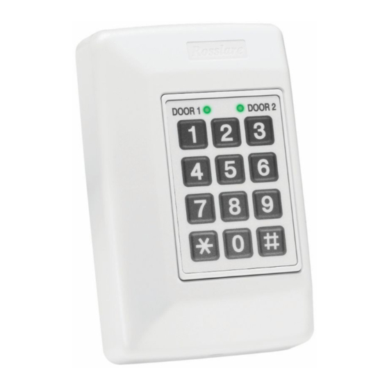
Rosslare AC-020 Hardware Installation And User's Manual
Indoor dual-door standalone controller
Hide thumbs
Also See for AC-020:
- Hardware installation and user's manual (50 pages) ,
- Hardware installation and user's manual (70 pages)

Related Manuals for Rosslare AC-020


Summary of Contents for Rosslare AC-020
- Page 1 AC-020 Indoor Dual-Door Standalone Controller DOOR 2 DOOR 1 Hardware installation and User Guide 08/06...
- Page 3 Grant of License. Rosslare and its suppliers grant you a nonexclusive license to use one copy of the enclosed software program (”Software”) on one computer with...
- Page 4 Upon any violation of any of the provisions of this Agreement, rights to use the Software shall automatically terminate and the Software must be returned to Rosslare or all copies of the Software destroyed. Limited Product Warranty. Rosslare...
- Page 5 Remedies. Rosslare’s entire liability and the licensees exclusive remedy for any breech of warranty, shall be, at Rosslare’s sole option, either a) return the price paid or b) repair or replacement of hardware or software, provided that the hardware is returned to the point of purchase, with a copy of the sales receipt.
- Page 6 Consistent with 48. C.F.R. 12.212 and 48 C.F.R. 227.7202-1 through 227.7204-1 (June 1995), or any successor regulations, this software is provided to the terms and conditions herein. Contractor/ Manufacturer Rosslare Enterprises Ltd. Wang Road, Hong...
-
Page 7: Table Of Contents
Typical Lock and Option Wiring ....18 Reader Wiring ..........18 Features and Concepts........19 Modes of Operation ........20 Changing the Modes of Operation ....22 Changing from Normal Mode to Secure Mode ..............22 AC-020 Page VII 08/06... - Page 8 Request to Exit (REX) Button ......26 Siren Sound ..........26 Programming Instructions ......27 Programming Menu Quick Reference Guide 28 Programming the AC-020 ....... 29 FOR DOOR 1 PROGRAM: ......29 FOR DOOR 2 PROGRAM: ......29 Entering Programming Mode ......32 Exiting Programming Mode ......
- Page 9 AY-X11 Series Prox Readers w/ Bell ..... 53 AY-X12 Series Prox Readers ......54 AY-X12 Series Prox Readers ......55 AY-X19 Series Pin & Prox Readers ....56 AY-L23 RF Reader ........56 Technical Support ........... 58 AC-020 Page IX 08/06...
-
Page 10: Introduction
The AC-020 provides a higher level of security as the programmer is normally placed in a secure location while the reader sensors are remotely located outside the controlled premises. - Page 11 During normal use, PIN codes that are employee codes can be entered only from reader sensor, while Special Codes may be entered either from AC-020 or from the reader. Topics in this section: Key Features •...
-
Page 12: Key Features
Key Features Here are some of the AC-020 key features: Supports two 26-Bit Wiegand compatible • Readers Three Modes of Operation • Normal Mode Bypass Mode Secure Mode Lock Strike Relay Output • Request to Exit (REX) button •... -
Page 13: Technical Specifications
5A Relay Lock Strike Power Supply: 12V DC constant voltage 1.2 A current limit Reader Power Supply: Voltage: 12V DC Max Current: 300mA Inputs Request to Exit (REX): N.O. Dry Contact Reader Input: 26-Bit Wiegand Compatible AC-020 Page 13 08/06... -
Page 14: Environmental Characteristics
Operating Temperature: -25°F to 145°F (-31°C to 63°C) Operating Humidity: 0 to 95% (Non- Condensing) Mechanical Characteristics Dimensions: 5.3” (134mm) L x 3.4” (85mm) W x 1.2” (30mm) D (Fits US Gang Box) Weight: 0.5 lbs (220g) AC-020 Page 14 08/06... -
Page 15: Installation
Installation The AC-020 has been designed for easy installation. Only a few steps are required to install the controller. In this section you will learn how to mount the controller in your desired location. You will learn how to wire the controller to its power source, which includes attaching the controller to a rechargeable Lead Acid battery. -
Page 16: Mounting The Controller
(Skip this step when attaching the AC-020 to a US Gang Box) Drill a hole for cables as indicated on the wiring template. -
Page 17: Power Wiring
Door 1 LED DOOR 1 DOOR 2 3 x 4 Matrix Keypad Case Screw Power Wiring POWER SUPPLY FROM TRANSFORMER 16V AC (1.5A, 25VA) DOOR 2 DOOR 1 12V DC LEAD ACID BATTERY UP TO 7 AH RECOMMENDED AC-020 Page 17 08/06... -
Page 18: Typical Lock And Option Wiring
DOOR 2 N.O. DOOR 1 REX 1 N.O. REX 2 DOOR 2 Reader Wiring DOOR 1 DOOR 2 READER DOOR 1 +12V +12V 12V DC, Max. 300mA READER +12V +12V DOOR 2 12V DC, Max. 300mA AC-020 Page 18 08/06... -
Page 19: Features And Concepts
Features and Concepts Now that you have installed your AC-020 controller, it is time to become familiar with its features and concepts. In this section you will learn about all the features that are programmable. They are the basic features of the AC-020 and can be programmed directly from the controller’s programming keypad. -
Page 20: Modes Of Operation
The following examples show the LED status of • Door 1 but are applicable to Door 2 as well. The AC-020 has three modes of operation Normal, Bypass, and Secure Mode. The three modes provide different levels of security. Normal Mode The DOOR 1 / DOOR 2 •... - Page 21 Release Time. In addition, it is possible to activate the Lock • Strike in the following ways: Pressing the REX button Master Codes (from an outside reader only using Prox. Code or Pin. Code) AC-020 Page 21 08/06...
-
Page 22: Changing The Modes Of Operation
LED will turn red You are now in Secure Mode • Changing from Secure Mode to Normal Mode The controller is in Secure Mode DOOR 1 / DOOR 2 • DOOR 1 DOOR 2 LED is red AC-020 Page 22 08/06... -
Page 23: Changing From Normal Mode To Bypass Mode
DOOR 1 DOOR 2 LED will flash orange ORANGE Press the “*/#” key, respectively. DOOR 1 / DOOR 2 • DOOR 1 DOOR 2 ORANGE LED will turn orange You are now in Bypass Mode • AC-020 Page 23 08/06... -
Page 24: Changing From Bypass Mode To Normal Mode
DOOR 2 DOOR 1 LED will flash green GREEN Press the “*/#” key, respectively. DOOR 1 / DOOR 2 • DOOR 1 DOOR 2 GREEN LED will turn green You are now in Normal Mode • AC-020 Page 24 08/06... -
Page 25: Events And Event Actions
However, applying the same code from the AC-020 keyboard will clear tamper output as well as opening Door 2 Lock Strike and stopping the siren (assuming no Door 1 tamper). -
Page 26: Request To Exit (Rex) Button
However, if the tamper condition at the other door exists, one is required to clear that tamper event as well, in order to stop the siren. Either way, the siren may stop on its own if the pre-programmed siren time has elapsed. AC-020 Page 26 08/06... -
Page 27: Programming Instructions
AC- 020’s features. Most of these features can be programmed via the AC-020’s programming keypad. The following pages describe how to program the AC-020 using the programming keypad. Topics in this section: Programming Menu Quick Reference Guide •... -
Page 28: Programming Menu Quick Reference Guide
Changing Lock Strike Code 2 Changing Program Code Changing Normal/Secure Code Changing Normal/Bypass Code Changing Door Release Time Choosing Fail Secure/Fail Safe Operation Enrolling Proximity Cards or Keyboard Codes Deleting Proximity Cards or Keyboard Codes Returning to Default Factory Setting AC-020 Page 28 08/06... -
Page 29: For Door 1 Program
Programming the AC-020 FOR DOOR 1 PROGRAM: Menu Function Initial Number Setting Changing Lock Strike Code 1 2580 Changing Lock Strike Code 2 0000* Changing Program Code 1234 Changing Normal/Secure 3838 Code Changing Normal/Bypass 0000* Code Changing Door Release Time... - Page 30 Setting *0000 deletes a function NOTE: You must be in NORMAL mode to program the AC-020. DOOR 1 / DOOR 2 LED will be green. Wrong or timed out entries will reset the controller to the NORMAL mode condition. To exit programming, press the “*/#” key for two seconds.
- Page 31 Wrong entries during programming may also abort programming, along with long beep generation. All programming operations are done either from the on-board keyboard or from the reader. Programming the PROX. employee codes requires using proximity reader and proximity cards. AC-020 Page 31 08/06...
-
Page 32: Entering Programming Mode
Entering Programming Mode To begin programming the controller’s settings, the AC-020 must first place into Programming Mode. You may only enter Programming mode from Normal mode, the controller does not permit entry to Programming Mode if the controller is in Bypass and Secure Mode. -
Page 33: Exiting Programming Mode
Normal Operating Mode. While in Programming Mode if no key is pressed for 30 seconds the AC-020 will emit a long beep and return to Normal Operating Mode. A short press on the “*” or “#” key may also return the controller to Normal Operating Mode, accompanied by a long beep. -
Page 34: Changing Lock Strike Code 1
Lock Strike Code 1. You will hear 3 beeps • The system will return to NORMAL mode • The default Lock Strike Code 1 is 2580 for • Door 1 and 0852 for Door 2 AC-020 Page 34 08/06... -
Page 35: Changing Lock Strike Code 2
? ? ? ? you wish to set as the new Programming Code. You will hear 3 beeps • The system will return to Normal mode • NOTE: There is no default code for Lock Strike Code 2. AC-020 Page 35 08/06... -
Page 36: Changing The Programming Code
Enter the new 4-digit code ? ? ? ? you wish to set as the new Programming Code NOTE: Programming Code cannot be erased. When trying to program code 0000, you will hear a AC-020 Page 36 08/06... - Page 37 Normal operating mode. AC-020 Page 37 08/06...
-
Page 38: Changing The Normal / Secure Code
GREEN The DOOR 2 LED will • flash red Enter the new 4-digit code ? ? ? ? you wish to set as the new Normal/Secure change code. You will hear 3 beeps • AC-020 Page 38 08/06... - Page 39 The system will return to Normal mode • (Default Secure code is 3838 for Door 1 and 8383 for Door 2.) AC-020 Page 39 08/06...
-
Page 40: Changing The Normal / Bypass Code
The DOOR 2 LED will • flash orange NOTE: The Normal / Bypass Code also controls the Chime function for the AC-020. You may set the code to 4 available options. Option 1: Disabling Bypass Mode - Disabling the Chime... - Page 41 0. The Bypass mode and the Chime function are enabled for both Normal mode and Bypass mode. You will hear 3 beeps • The system will return to Normal mode • NOTE: No default Bypass code exists. AC-020 Page 41 08/06...
-
Page 42: Changing The Door Release Time
DOOR 2 GREEN turn green The DOOR 2 LED will • turn off Press 6 The DOOR 1 LED will • DOOR 1 DOOR 2 remain green GREEN GREEN The DOOR 2 LED will • flash green AC-020 Page 42 08/06... - Page 43 0512 means fail secure with a 5- minute tamper alarm sound time and a 12 second door release.) You will hear 3 beeps. • The system will return to Normal mode. • Default door open time is 4 seconds. • AC-020 Page 43 08/06...
-
Page 44: Enrolling Proximity Cards/Pin Codes Into The System
If an unassigned proximity card is enrolled at an occupied slot, the AC-020 will generate a long beep and wait for another slot number to be entered. The card at the current slot location must be erased first, before a new code is programmed on that slot number. - Page 45 The DOOR 2 LED will stop flashing • Enter the 4-digit keyboard based employee • code designated for this slot number to the reader The DOOR 2 LED will stop flashing • AC-020 Page 45 08/06...
- Page 46 NOTE: The AC-020 programmer will not accept employee codes that are already allocated to a slot. The AC-020 will signal this with a long beep and the DOOR 2 LED will continue to flash green.
-
Page 47: Deleting Proximity Cards/Pin Codes From The System
The DOOR 2 LED will • turn red Enter the 3-digit slot ? ? ? code you wish to delete from the system The DOOR 2 LED will • DOOR 1 DOOR 2 flash red ORANGE AC-020 Page 47 08/06... - Page 48 IMPORTANT: Ensure that your record of employees and their assigned slot numbers are stored in a secure location. Then, if you wish to delete a lost or stolen employee code from the system, you can identify the card number from your record. AC-020 Page 48 08/06...
-
Page 49: Return To Factory Default Settings
DOOR 1 DOOR 2 GREEN turn green The DOOR 2 LED will • turn off Press 0 The DOOR 1 LED will • DOOR 2 DOOR 1 flash red The DOOR 2 LED will • flash red AC-020 Page 49 08/06... - Page 50 Doing so will erase all of the employee codes from the memory and all of the special codes will return their default values. preprogrammed cards, codes and special codes will have to be preprogrammed from the beginning. AC-020 Page 50 08/06...
-
Page 51: Replacing A Lost Programming Code
Programming Mode so that you may create a new Programming Code. The AC-020 must be in Normal Mode otherwise this will not work. Make sure that the DOOR 1 / DOOR 2 LED is green before proceeding. Disconnect power from the AC-020... -
Page 52: Replacing A Lost Normal / Secure Code
Normal Mode so that you may program a new Normal / Secure Code. The AC-020 must be in Secure Mode otherwise this will not work. Make sure that the DOOR 1 / DOOR 2 LED is red before proceeding. -
Page 53: Accessories
For indoor use • Slim Stylish Design (Mullion) • Includes LED Indicator • Audible Buzzer Indicator • Built in Tamper (w/ Rosslare Controllers) • Includes Bell Button (w/ Rosslare Controllers) • AY-X11 Series Prox Readers w/ Bell AC-020 Page 53... -
Page 54: Ay-X12 Series Prox Readers
• Slim Stylish Design (USA Gang Box) • Bi-Color Light Indicator • Audible Buzzer Indicator • Built in Tamper (w/ Rosslare Controllers) • Includes Bell Button (w/ Rosslare Controllers) • AY-X12 Series Prox Readers AY-C11 / AY-D11 Reading Distance: 8 to 10cm •... -
Page 55: Ay-X12 Series Prox Readers
RF Modulation: ASK at 125 kHz • For outdoor use • Slim Stylish Design (UK or USA Gang Box, • Mullion) Bi-Color Light Indicator • Includes LED Control Input • Audible Buzzer Indicator • Built in Tamper Output • AC-020 Page 55 08/06... -
Page 56: Ay-X19 Series Pin & Prox Readers
For indoor use • Slim Stylish Design (USA Gang Box) • Bi-Color Light Indicator • Audible Buzzer Indicator • Built in Tamper (w/ Rosslare Controllers) • Includes Bell Button (w/ Rossalare • Controllers) AY-L23 RF Reader AC-020 Page 56 08/06... - Page 57 For Outdoor Use (Water Proof) • Frequency: 433MHz • Slim Stylish Design (Mullion) • Bi-Color LED Indicator • LED Control • Audible Buzzer Indicator • Size: 145mm x 43mm x 20mm • Used with SA-26 Wireless Remote • AC-020 Page 57 08/06...
-
Page 58: Technical Support
Technical Support Asia Pacific, Middle East, Africa Rosslare Security Products Headquarters 905-912 Wing Fat Industrial Bldg, 12 Wang Tai Road, Kowloon Bay Hong Kong Tel: +852 2795-5630 Fax: +852 2795-1508 E-mail: support.apac@rosslaresecurity.com United States and Canada 1600 Hart Court, Suite 103... - Page 59 AC-020 Page 59 08/06...
- Page 61 www.rosslaresecurity.com...
Need help?
Do you have a question about the AC-020 and is the answer not in the manual?
Questions and answers