
Related Manuals for Quanmax QutePC-2000


Summary of Contents for Quanmax QutePC-2000
- Page 1 QutePC-2000 Fan-less Mini-PC with Intel® Atom Processor N270 User’s Guide QutePC‐2000 User’s Manual ...
- Page 2 © 2009 Quanmax Inc. All rights reserved. The information in this user’s guide is provided for reference only. Quanmax does not assume any liability arising out of the application or use of the information or products described herein. This user’s guide may contain or reference information and products protected by copyrights or patents and does not convey any license under the patent rights of Quanmax, nor the rights of others.
-
Page 3: Table Of Contents
Content Content Content ........................3 Figures & Tables ......................4 Safety Instructions ...................... 5 Before You Begin .................. 5 When Working Inside a Computer ............5 Preventing Electrostatic Discharge ............6 Instructions for Lithium Battery ............. 7 ... -
Page 4: Figures & Tables
Figures & Tables Figures & Tables Figure 1 QutePC-2000 dimensions drawing ..........14 Figure 2 Front Panel .................. 15 Figure 3 Rear Panel ................... 17 Figure 4 Connect the DVI cable ..............19 Figure 5 Connecting USB mouse & keyboard..........20 Figure 6 Network cable with RJ45 connector .......... -
Page 5: Safety Instructions
Use extreme caution when installing or removing components. Refer to the installation instructions in this user’s guide for precautions and procedures. If you have any questions, please contact Quanmax Post-Sales Technical Support. Access can only be gained by service persons or by users who have been instructed about the reasons for the restrictions applied to the location and about any precautions that shall be taken;... -
Page 6: Preventing Electrostatic Discharge
Static electricity can harm system boards. Perform service at an ESD workstation and follow proper ESD procedure to reduce the risk of damage to components. Quanmax strongly encourages you to follow proper ESD procedure, which can include wrist straps and smocks, when servicing equipment. -
Page 7: Instructions For Lithium Battery
(e.g. to the collecting points for disposal of batteries) Voltage Ratings The external power adaptor of the QutePC-2000 has the following voltage ratings: Input: 100-240 VAC, 50-60 Hz Output: 30W, 12-19Vdc, 2.5-1.58A... -
Page 8: Preface
Remove all items from the box. If any items listed on the purchase order are missing, notify Quanmax customer service immediately. Inspect the product for damage. If there is damage, notify Quanmax customer service immediately. Refer to “Warranty Policy” for the return procedure. -
Page 9: Warranty Policy
Quanmax or its authorized agent; or if the failure is caused by accident, acts of God, or other causes beyond the control of Quanmax or the manufacturer. Neglect, misuse, and abuse shall include any installation, operation, or maintenance of the product other than in accordance with the user’s guide. -
Page 10: Maintaining Your Computer
Quanmax. Limitation of Liability In no event shall Quanmax be liable for any defect in hardware, software, loss, or inadequacy of data of any kind, or for any direct, indirect, incidental, or consequential damages in connection with or arising out of the performance or use of any product furnished hereunder. -
Page 11: Power Protection
Preface turning it on. Failure to do so may cause damage to internal components, particularly the hard disk drive. Humidity High-humidity can cause moisture to enter and accumulate in the system. This moisture can cause corrosion of internal components and degrade such properties as electrical resistance and thermal conductivity. - Page 12 Preface Line conditioners keep a system’s AC power source voltage at a fairly constant level and, therefore, can handle brownouts. Because of this added protection, line conditioners cost more than surge protectors. However, line conditioners cannot protect against a complete loss of power. Uninterruptible Power Supply Uninterruptible power supply (UPS) systems offer the most complete protection against variations on power because they use battery power to keep the server...
-
Page 13: Chapter 1 Introduction
Chapter 1 Introduction Overview The QutePC-2000 is a mini PC is ideal for space critical applications. This system is designed with Intel® Atom N270 Processor which provides with excellent performance enabled by next- generation 45nm Process Technology. The system is supported with Intel®... -
Page 14: Product Specifications
Optional Mini PCIe WI-FI Card Wireless LAN Fanless Cooling Input: 100-240 VAC, 50-60 Hz Power Unit Output: 30W, 12-19Vdc, 2.5-1.58A Operating Temp. 0~40 C Desktop, VESA-mount Mounting CE, FCC Class B Certifications Table 1 QutePC-2000 product specifications Figure 1 QutePC-2000 dimensions drawing QutePC‐2000 User’s Manual ... -
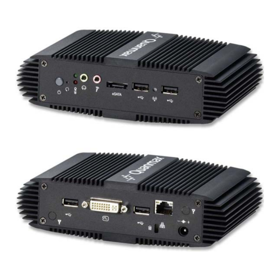
Page 15: System Tour
Chapter 1 System tour Refer to the diagrams below to identify the components of the system. Front Panel Figure 2 Front Panel The USB (Universal Serial Bus) port is compatible with USB devices such as keyboards, mouse devices, cameras, and hard disk drives. USB allows many devices to run simultaneously on a single computer, with some peripheral acting as additional plug-in sites or hubs. - Page 16 Chapter 1 MIC-IN The microphone jack is designed to connect the microphone used for video conferencing, voice narrations, or simple audio recordings. Headphone Jack The stereo headphone jack (3.5mm) is used to connect the system’s audio out signal to amplified speakers or headphones. Power LED The power LED will light when the PC is power-on.
-
Page 17: Figure 3 Rear Panel
Chapter 1 Rear Panel Figure 3 Rear Panel The USB (Universal Serial Bus) port is compatible with USB devices such as keyboards, mouse devices, cameras, and hard disk drives. USB allows many devices to run simultaneously on a single computer, with some peripheral acting as additional plug-in sites or hubs. - Page 18 Chapter 1 Kensington Lock Slot The slot is used for attaching a lock-and-cable apparatus. Locks are generally secured in place with a key or combination lock attached to a rubberized metal cable. QutePC‐2000 User’s Manual ...
-
Page 19: Chapter 2 Getting Started
Chapter 2 Chapter 2 Getting Started Setting up your PC Connecting the monitor Connect the DVI cable from your display to the DVI port. Figure 4 Connect the DVI cable NOTE To connect a VGA display, you need the DVI to VGA adapter to connect a display with a VGA connector. -
Page 20: Figure 5 Connecting Usb Mouse & Keyboard
Chapter 2 Connecting USB mouse & keyboard Your QutePC-2000 does not come with a keyboard and mouse, but you can use any USB keyboard or mouse with your computer. Figure 5 Connecting USB mouse & keyboard NOTE Using a third-party USB mouse or keyboard may require software drivers. -
Page 21: Mounting Your Pc To A Monitor
Chapter 2 Turning on the system Connect the power adapter cable to the DC jack (DC IN) of the QutePC-2000 Connect the power cable to the power adapter Connect the power cable to a power outlet Press the power switch on the front panel to turn on the system... -
Page 22: Anti-Theft Protection With A Kensington Lock
Figure 9 VESA Mounting Kit Dimension Anti-theft protection with a Kensington Lock The QutePC-2000 has a Kensington lock slot for the Kensington MicroSaver. With the Kensington MicroSaver, a sturdy steel cable, you can attach your QutePC-2000 to a stationary object and protect your PC from theft. -
Page 23: Chapter 3 Ami Bios Setup
This chapter provides a description of the AMI BIOS. The BIOS setup menus and available selections may vary from those of your product. For specific information on the BIOS for your product, please contact Quanmax. NOTE: The BIOS menus and selections for your product may vary from those in this chapter. -
Page 24: Main Menu
Chapter 3 Main Menu The BIOS Setup is accessed by pressing the DEL key after the Power-On Self-Test (POST) memory test begins and before the operating system boot begins. Once you enter the BIOS Setup Utility, the Main Menu will appear on the screen. The Main Menu provides System Overview information and allows you to set the System Time and Date. -
Page 25: Advanced Menu
Chapter 3 not previously formatted with LBA mode disabled. Options: Disabled, Auto DMA Mode [Auto] Options: Auto S.M.A.R.T [Auto] SMART stands for Smart Monitoring, Analysis, and Reporting Technology. It allows AMIBIOS to use the SMART protocol to report server system information over a network. -
Page 26: Table 6 Onboard Peripherals Configuration Settings
Chapter 3 Table 6 OnBoard Peripherals Configuration Settings BIOS SETUP UTILITY M a i n B o o t C h i p s e t P o w e r S e c u r i t y E x i t A d v a n c e d OnBoard Peripherals Configuration Settings Options... -
Page 27: Boot Menu
Chapter 3 Table 7 Hardware Health Configuration BIOS SETUP UTILITY M a i n B o o t C h i p s e t P o w e r S e c u r i t y E x i t A d v a n c e d Hardware Health Configuration Disabled... -
Page 28: Chipset Menu
Chapter 3 Bootup Num-Lock [On] Allow you to select the power-on state for the NumLock. Options: Off, On Wait for ‘F1’ If Error [Enabled] When set to Enabled, the system waits for F1 key to be pressed when error occurs. Options: Disabled, Enabled Hit ‘DEL’... -
Page 29: Power Menu
Chapter 3 Power Menu Table 10 Power Menu BIOS SETUP UTILITY M a i n A d v a n c e d B o o t C h i p s e t S e c u r i t y E x i t P o w e r Power Management Setting... -
Page 30: Security Menu
Chapter 3 Security Menu Table 11 Security Menu BIOS SETUP UTILITY M a i n A d v a n c e d B o o t C h i p s e t P o w e r E x i t S e c u r i t y Security Setting Install or Change the password. - Page 31 Chapter 3 Save Changes and Exit Exit system setup after saving the changes. Once you are finished making your selections, choose this option from the Exit menu to ensure the values you selected are saved to the CMOS RAM. The CMOS RAM is sustained by an onboard backup battery and stays on even when the PC is turned off.
-
Page 32: Chapter 4 Driver Installation
Chapter 4 Driver Installation If your QutePC-2000 does not come with an operating system pre-installed, you will need to install an operating system and the necessary drivers to operate it. After you have finished assembling your system and connected the appropriate power source, power it up using the power supply and install the desired operating system. -
Page 33: Chapter 5 Faq & Troubleshooting
HDD. Q3: How to set the WOL (Wake on LAN) function? A3: WOL function is the default support in QutePC-2000 so you don’t do any modification setting in QutePC-2000 BIOS. Q4: How much current provided from QutePC-2000 USB ports? A4: 500mA QutePC‐2000 User’s Manual ... -
Page 34: Troubleshooting
NG. 1.3. If you could not press the power button, its function is fail. 1.4. If power button could be pressed but Power-LED of QutePC-2000 didn’t be lighted, the power button fail. 1.5. If Power-LED of QutePC-2000 lighted and the system could not power off after keep pressing the power button 4 seconds, the power button fail.
Need help?
Do you have a question about the QutePC-2000 and is the answer not in the manual?
Questions and answers