Table of Contents
Advertisement
Quick Links
Advertisement
Table of Contents

Subscribe to Our Youtube Channel
Related Manuals for Transition Networks SM24-1000SFP-AH


Summary of Contents for Transition Networks SM24-1000SFP-AH
- Page 1 SM24-1000SFP-AH Gigabit Ethernet Switch Installation Guide...
- Page 3 Installation Guide SM24-1000SFP-AH Gigabit Ethernet Switch Layer 2 FTTH Switch with 24 Gigabit Ethernet SFP Slots, 2 10-Gigabit Ethernet XFP Slots, 2 10-Gigabit Ethernet Extender Module Slots (XFP), 1 Fast Ethernet Management Port (RJ-45)
- Page 4 SM24-1000SFP-AH E112009-DT-R01...
- Page 5 Compliances and Safety Warnings FCC - Class A This equipment has been tested and found to comply with the limits for a Class A digital device, pursuant to part 15 of the FCC Rules. These limits are designed to provide reasonable protection against harmful interference when the equipment is operated in a commercial environment.
-
Page 6: Safety Compliance
CE Mark Declaration of Conformance for EMI and Safety (EEC) This information technology equipment complies with the requirements of the Council Directive 89/336/EEC on the Approximation of the laws of the Member States relating to Electromagnetic Compatibility and 73/23/EEC for electrical equipment used within certain voltage limits and the Amendment Directive 93/68/EEC. -
Page 7: Power Cord Safety
Warnhinweis: Faseroptikanschlüsse - Optische Sicherheit Niemals ein Übertragungslaser betrachten, während dieses LASERGER ÄT eingeschaltet ist. Niemals direkt auf den Faser-TX-Anschluß und auf DER KLASSE I die Faserkabelenden schauen, während diese eingeschaltet sind. Power Cord Safety Please read the following safety information carefully before installing the switch: Warning: Installation and removal of the unit must be carried out by qualified personnel only. - Page 8 Power Cord Set Denmark The supply plug must comply with Section 107-2-D1, Standard DK2-1a or DK2-5a. Switzerland The supply plug must comply with SEV/ASE 1011. U.K. The supply plug must comply with BS1363 (3-pin 13 A) and be fitted with a 5 A fuse which complies with BS1362. The mains cord must be <HAR>...
- Page 9 Cordon électrique - Il doit être agréé dans le pays d’utilisation Etats-Unis et Le cordon doit avoir reçu l’homologation des UL et un certificat de la CSA. Canada: Les spécifications minimales pour un cable flexible sont AWG No. 18, ou AWG No. 16 pour un cable de longueur inférieure à 2 mètres. - type SV ou SJ - 3 conducteurs Le cordon doit être en mesure d’acheminer un courant nominal d’au...
-
Page 10: Warnings And Cautionary Messages
Stromkabel . Dies muss von dem Land, in dem es benutzt wird geprüft werden: Schweiz Dieser Stromstecker muß die SEV/ASE 1011Bestimmungen ein- halten. Europe Das Netzkabel muß vom Typ HO3VVF3GO.75 (Mindestanforderung) sein und die Aufschrift <HAR> oder <BASEC> tragen. Der Netzstecker muß die Norm CEE 7/7 erfüllen (”SCHUKO”). PSE Alarm 本製品に同梱いたしております電源コードセットは、... -
Page 11: End Of Product Life Span
End of Product Life Span This product is manufactured in such a way as to allow for the recovery and disposal of all included electrical components once the product has reached the end of its life. Manufacturing Materials There are no hazardous nor ozone-depleting materials in this product. Documentation All printed documentation for this product uses biodegradable paper that originates from sustained and managed forests. - Page 12 viii...
-
Page 13: Table Of Contents
Contents Chapter 1: Introduction Overview Switch Architecture Network Management Options Description of Hardware SFP Slots XFP Slots 100BASE-TX Management Port Console Port Alarm Interface Port Port and System Status LEDs Fan Tray Power Modules Features and Benefits Connectivity Expandability Performance Management Chapter 2: Network Planning Fiber-To-The-Home (FTTH) - Page 14 Contents Installing an Optional SFP/XFP Transceiver Grounding the Chassis Connecting to a Power Source Connecting DC Power Connecting AC Power Connecting to the Console Port 3-10 Wiring Map for Serial Cable 3-10 Connecting to the Alarm Port 3-11 Wiring Map for Alarm Cable 3-11 Chapter 4: Making Network Connections Connecting Network Devices...
- Page 15 Contents Appendix C: Specifications Physical Characteristics Switch Features Management Features Standards Compliances Extender Modules 10 Gigabit Extender Module (XFP) Glossary Index...
- Page 16 Tables Table 1-1 Port and System Status LEDs Table 3-1 Serial Cable Wiring 3-10 Table 3-2 Alarm Cable Wiring 3-11 Table 4-1 Maximum 10GBASE-SR 10 Gigabit Ethernet Cable Length Table 4-2 Maximum 10GBASE-LR 10 Gigabit Ethernet Cable Length Table 4-3 Maximum 10GBASE-ER 10 Gigabit Ethernet Cable Length Table 4-4 Maximum 1000BASE-T Gigabit Ethernet Cable Length...
- Page 17 Figures Figure 1-1 Front Panel Figure 1-2 Single-Port 10GBASE Module (XFP) Figure 1-3 Port and System LEDs Figure 1-4 Fan Tray Figure 1-5 Optional Power Modules Figure 2-1 Downlink Fiber Connections Figure 2-2 Uplink Fiber Connections Figure 2-3 Management Port Connections Figure 2-4 Private VLAN Connections Figure 3-1...
- Page 18 Figures...
-
Page 19: Chapter 1: Introduction
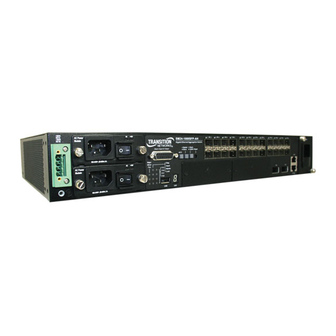
IEEE 802.1Q compliant VLANs, and empowers multimedia applications with multicast switching and quality of service priority queueing. System and Port indicators SFP Subscriber Ports Ground and Power Connection Points Power Trays SM24-1000SFP-AH Gigabit Ethernet Aggregation Switch XFP Uplink Ports Alarm Connector Fan Tray Console Port... -
Page 20: Switch Architecture
Introduction Switch Architecture This switch employs a wire-speed, non-blocking switching fabric. This permits simultaneous wire-speed transport of multiple packets at low latency on all ports. The switch also features full-duplex capability on all ports, which effectively doubles the bandwidth of each connection. For communications within the same VLAN, the switch uses store-and-forward switching to ensure maximum data integrity. -
Page 21: Xfp Slots
Description of Hardware Note that 1000BASE-SX transceivers use multimode duplex fiber cable, 1000BASE-LX and 1000BASE-LH transceivers use single-mode duplex fiber cable, and 1000BASE-BX10-U transceivers use single-mode simplex fiber cable. XFP Slots The switch includes two slots for 10 Gigabit Ethernet XFP compliant fiber-optic transceivers, and two additional slots for optional XFP transceiver modules (shown below). -
Page 22: Port And System Status Leds
The LEDs, which are located on the front panel and the power module trays for easy viewing, are shown below and described in the following tables. SM24-1000SFP-AH Gigabit Ethernet Aggregation Switch Figure 1-3 Port and System LEDs... -
Page 23: Fan Tray
Description of Hardware Table 1-1 Port and System Status LEDs (Continued) Condition Status Green Stacking mode selected. Stack Uplink mode selected. Master* Green Operating in stack master mode. Amber Operating in stack slave mode. Not operating in stack mode. Link/Activity Green Port has a valid link. -
Page 24: Power Modules
Introduction Power Modules This switch provides three power module options: -48 VDC and universal AC. For specifications on the power conversion modules and external input power requirements, see “Power Supply” on page C-2. Figure 1-5 Optional Power Modules Features and Benefits Connectivity •... -
Page 25: Performance
Features and Benefits Performance • Transparent bridging. • Aggregate duplex bandwidth of up to 88.1 Gbps. • Switching table with a total of 16K MAC address entries and 1K static addresses. • Provides store-and-forward switching for intra-VLAN traffic. • Supports wire-speed switching. •... - Page 26 Introduction...
-
Page 27: Chapter 2: Network Planning
Chapter 2: Network Planning Fiber-To-The-Home (FTTH) Fiber-To-The-Home (FTTH) has always been an attractive option for Internet access. It has all the benefits of optical fiber. It provides a future-proof network by avoiding the hassle of having to upgrade from ADSL to XDSL, or digital coax to digital wireless. -
Page 28: Connection Examples
10 km away. A CPE is installed inside a subscriber’s premises, so there are no active outside components between the CO and the end user. The figure below illustrates a basic switch to CPE connection. Central Office (CO) FTTH Switch SM24-1000SFP-AH Gigabit Ethernet Aggregation Switch Subscriber’s Home 10/100/1000BASE-T UTP 1000BASE-LX... -
Page 29: Uplink Connections
The figure below illustrates a trunk connection to other switches. Internet Link to Internet POP 10GBASE-ER fiber trunk connection to Layer 2/3 switch (up to 40 km) SM24-1000SFP-AH Gigabit Ethernet Aggregation Switch SM24-1000SFP-AH Gigabit Ethernet Aggregation Switch First Level Fiber Aggregation Switch or Layer 3 Router... -
Page 30: Management Connections
The figure below illustrates management-port connections to FTTH switches. Ethernet Switch Management Station SM24-1000SFP-AH Gigabit Ethernet Aggregation Switch SM24-1000SFP-AH Gigabit Ethernet Aggregation Switch 10/100BASE-TX UTP connections... -
Page 31: Private Vlan Connections
The figure below illustrates Private VLAN connections to the switch. To uplink Layer 2/3 switch FTTH Switch Ports 25, 26 SM24-1000SFP-AH Gigabit Ethernet Aggregation Switch Port 8 Ports 18, 19, 20 Private VLAN 1... -
Page 32: Application Notes
Network Planning Application Notes Full-duplex operation only applies to point-to-point access (such as when a switch is attached to a workstation, server or another switch). When the switch is connected to a hub, both devices must operate in half-duplex mode. To interconnect distinct VLANs or IP subnets, you can attach the switch to a standard Layer 3 router. -
Page 33: Chapter 3: Installing The Switch
Chapter 3: Installing the Switch Selecting a Site Switches can be mounted in a standard 19-inch equipment rack or on a flat surface. Be sure to follow the guidelines below when choosing a location. • The site should: - restrict access to authorized service personnel in accordance with IEC 60950-1. A restricted access location is one where access is secure and limited to service personnel who have a special key, or other means of security. -
Page 34: Equipment Checklist
Then, before beginning the installation, be sure you have all other necessary installation equipment. Package Contents • 26-port Gigabit Ethernet Switch (SM24-1000SFP-AH) • Four adhesive foot pads • Bracket Mounting Kit containing two brackets and eight screws for attaching the brackets to the switch •... -
Page 35: Mounting
Mounting Mounting A switch unit can be mounted in a standard 19-inch equipment rack or on a desktop or shelf. Mounting instructions for each type of site follow. Rack Mounting Before rack mounting the switch, pay particular attention to the following factors: •... -
Page 36: Desktop Or Shelf Mounting
Installing the Switch Mount the device in the rack, using four rack-mounting screws (not provided). C ra P 2 5 P 2 5 P 2 6 P 2 6 C o n s o le Figure 3-3 Installing the Switch in a Rack If installing a single switch only, turn to “Connecting to a Power Source”... -
Page 37: Installing An Optional Module Into The Switch
Installing an Optional Module into the Switch If installing a single switch only, go to “Connecting to a Power Source” at the end of this chapter. If installing multiple switches, attach four adhesive feet to each one. Place each device squarely on top of the one below, in any order. Installing an Optional Module into the Switch S M 2 4 - 1 0 0 0... -
Page 38: Installing An Optional Sfp/Xfp Transceiver
Installing the Switch To confirm that the module is correctly installed and ready to use, connect an active device to the module, and verify that the corresponding port indicator on the switch’s front panel turns green to show that there is a valid link. Installing an Optional SFP/XFP Transceiver C r a ft P 2 5... -
Page 39: Grounding The Chassis
Grounding the Chassis Grounding the Chassis Before powering on the switch, ground the switch to earth as described below. Ensure that the rack on which the switch is to be mounted is properly grounded and in compliance with ETSI ETS 300 253. Ensure that there is a good electrical connection to the grounding point on the rack (no paint or isolating surface treatment). -
Page 40: Figure 3-7 Dc Plug Connections
Installing the Switch 4. When using two power conversion modules with the switch, either AC or DC modules can be used – both AC, both DC, or one AC and one DC. To connect the switch to a power source: First verify that the external DC power supply can provide -36 to -72 VDC, 4 A minimum for the -48 VDC power conversion module. -
Page 41: Connecting Ac Power
Connecting to a Power Source At the power source, turn on the power for the feed lines or power bus. 10. After the power source is tuned on, set the power button on the front of the power conversion module to the ON position (marked “–”). 11. -
Page 42: Connecting To The Console Port
Installing the Switch Check the indicators on the power module as the switch is powered on to verify that the AC LED indicating external power status is on, and that the +12V LED indicating internal power conversion is on. If not, recheck the power supply and power cable connections at the supply source and at power module. -
Page 43: Connecting To The Alarm Port
Connecting to the Alarm Port Connecting to the Alarm Port The DB-15 alarm port on the switch’s front panel is used to provide alarm, service port, and BITS clock reference interfaces. The switch supports two sets of alarm relay contacts (major and minor), and 4 external customer site alarm inputs. It also provides an alarm cutoff button (labeled ACO). -
Page 44: Figure 3-11 External Alarm I/O Connections
Installing the Switch The following figure shows the pinout information for the DB-15 ALARM connector on the front panel. Alarm Connector Major Alarm Minor Alarm External Alarm Input 1 To backplane via internal signal External Alarm Input 2 converter circuits. External input uses dry relay contact External Alarm Input 3 to pins 14, 15, 13 and 8 for grounding. -
Page 45: Chapter 4: Making Network Connections
Chapter 4: Making Network Connections Connecting Network Devices This switch is designed to interconnect multiple segments (or collision domains). It can be connected to network cards in PCs and servers, as well as to hubs, switches or routers. It may be connected to devices using optional SFP or XFP transceivers. Twisted-Pair Devices Each device requires an unshielded twisted-pair (UTP) cable with RJ-45 connectors at both ends. -
Page 46: Connecting To Pcs, Servers, Hubs And Switches
Making Network Connections Connecting to PCs, Servers, Hubs and Switches Attach one end of a twisted-pair cable segment to the device’s RJ-45 connector. Figure 4-1 Making Twisted-Pair Connections If the device is a PC card and the switch is in the wiring closet, attach the other end of the cable segment to a modular wall outlet that is connected to the wiring closet. -
Page 47: Figure 4-2 Making Connections To Sfp Transceivers
1 Gbps Fiber Optic Connections Warning: These switches use lasers to transmit signals over fiber optic cable. The lasers are compliant with the requirements of a Class 1 Laser Product and are inherently eye safe in normal operation. However, you should never look directly at a transmit port when it is powered on. -
Page 48: Gbps Fiber Optic Connections
Making Network Connections The 1000BASE-SX/LX/LH and 1000BASE-BX10-U fiber optic ports operate at 1 Gbps full duplex. The maximum length for fiber optic cable operating at Gigabit speeds will depend on the fiber type as listed under “1000 Mbps Gigabit Ethernet Cable Lengths”... -
Page 49: Connectivity Rules
Connectivity Rules C r a f P 2 5 P 2 5 P 2 6 P 2 6 P 2 8 C o n s o l e Figure 4-3 Connecting to an XFP Transceiver As a connection is made, check the Link LED on the module to be sure that the connection is valid. -
Page 50: 10 Gbps Ethernet Collision Domain
Making Network Connections 10 Gbps Ethernet Collision Domain Table 4-1 Maximum 10GBASE-SR 10 Gigabit Ethernet Cable Length Fiber Size Fiber Bandwidth Maximum Cable Length Connector 62.5/125 micron 160 MHz/km 2-26 m single-mode fiber (7-85 ft.) 62.5/125 micron 200 MHz/km 2-33 m single-mode fiber (7-108 ft.) 50/125 micron... -
Page 51: 100 Mbps Fast Ethernet Cable Lengths
Cable Labeling and Connection Records Table 4-7 Maximum 1000BASE-LH Gigabit Ethernet Cable Length Fiber Size Fiber Bandwidth Maximum Cable Length Connector 9/125 micron 2 m - 40 km (7 ft - 24.9 miles) LC single-mode fiber Table 4-8 Maximum 1000BASE-BX10-U Gigabit Ethernet Cable Length Fiber Size Fiber Bandwidth Maximum Cable Length... - Page 52 Making Network Connections • Use sequential numbers for cables that originate from the same equipment. • Differentiate between racks by naming accordingly. • Label each separate piece of equipment. • Display a copy of your equipment map, including keys to all abbreviations at each equipment rack.
-
Page 53: Appendix A: Troubleshooting
Appendix A: Troubleshooting Diagnosing Switch Indicators This switch can be easily monitored through panel indicators to identify problems. The table below describes common problems you may encounter and possible solutions. Table A-1 Troubleshooting Chart Symptom Possible Cause Action Power Module LED is off Power outlet, power cord, •... -
Page 54: Power And Cooling Problems
Troubleshooting Power and Cooling Problems If the power indicator does not turn on when the power cord is plugged in, you may have a problem with the power outlet, power cord, or internal power supply. However, if the unit powers off after running for a while, check for loose power connections, power losses or surges at the power outlet, and verify that the fans on the unit are unobstructed and running prior to shutdown. -
Page 55: Appendix B: Cables
Appendix B: Cables Twisted-Pair Cable and Pin Assignments For 10/100BASE-TX connections, the twisted-pair cable must have two pairs of wires. For 1000BASE-T connections the twisted-pair cable must have four pairs of wires. Each wire pair is identified by two different colors. For example, one wire might be green and the other, green with white stripes. -
Page 56: Straight-Through Wiring
Cables Table B-1 10/100BASE-TX MDI and MDI-X Port Pinouts MDI Signal Name MDI-X Signal Name Transmit Data plus (TD+) Receive Data plus (RD+) Transmit Data minus (TD-) Receive Data minus (RD-) Receive Data plus (RD+) Transmit Data plus (TD+) Receive Data minus (RD-) Transmit Data minus (TD-) 4,5,7,8 Not used... -
Page 57: Crossover Wiring
Twisted-Pair Cable and Pin Assignments Crossover Wiring If the twisted-pair cable is to join two ports and either both ports are labeled with an “X” (MDI-X) or neither port is labeled with an “X” (MDI), a crossover must be implemented in the wiring. (When auto-negotiation is enabled for any RJ-45 port on these switches, you can use either straight-through or crossover cable to connect to any device type.) You must connect all four wire pairs as shown in the following diagram to support... -
Page 58: 1000Base-T Pin Assignments
Cables 1000BASE-T Pin Assignments All 1000BASE-T ports support automatic MDI/MDI-X operation, so you can use straight-through cables for all network connections to PCs or servers, or to other switches or hubs. The table below shows the 1000BASE-T MDI and MDI-X port pinouts. These ports require that all four pairs of wires be connected. -
Page 59: Cable Testing For Existing Category 5 Cable
Fiber Standards Cable Testing for Existing Category 5 Cable Installed Category 5 cabling must pass tests for Attenuation, Near-End Crosstalk (NEXT), and Far-End Crosstalk (FEXT). This cable testing information is specified in the ANSI/TIA/EIA-TSB-67 standard. Additionally, cables must also pass test parameters for Return Loss and Equal-Level Far-End Crosstalk (ELFEXT). -
Page 60: Usb Cabling
Cables USB Cabling The access device provides one USB 2.0 downstream port for connecting memory devices (e.g., memory stick or disk). The port can operate at either 1.5 or 12 Mbps, and deliver 5V power to the connected device at a maximum current of up to 500mA. -
Page 61: Appendix C: Specifications
Appendix C: Specifications Physical Characteristics Ports 24 Gigabit Ethernet SFP slots 2 10-Gigabit Ethernet XFP Slots 2 10-Gigabit Ethernet Extender Module Slots (XFP) 1 Fast Ethernet management port (RJ-45) 1 USB 2.0 port for memory stick (operates at 1.5 Mbps or 12 Mbps) Network Interface Ports 1-24: SFP transceiver slot, 10/100/1000 Mbps, full-duplex Ports 27-28: XFP transceiver slot, /100/1000/10000 Mbps, full-duplex... -
Page 62: Switch Features
Specifications Temperature Operating: -20 to 65 °C (-4 to 149 °F) Storage: -40 to 70 °C (-40 to 158 °F) Humidity Operating: 5% to 95% (non-condensing) Power Supply These power modules are offered: -48 VDC: (-36 to -72 VDC input range),2.0 A @ -48 VDC 100-240 VAC: (100 to 240 VAC, 50-60 Hz input range), 1 A Power Consumption 60 Watts (with two expansion modules) -
Page 63: Standards
Standards Software Loading TFTP in-band, or XModem out-of-band Standards IEEE 802.3-2005 Ethernet, Fast Ethernet, Gigabit Ethernet Link Aggregation Control Protocol (LACP) Full-duplex flow control (ISO/IEC 8802-3) IEEE 802.3ae 10 Gigabit Ethernet IEEE 802.1D Spanning Tree Protocol IEEE 802.1w Rapid Spanning Tree Protocol IEEE 802.1s Multiple Spanning Tree Protocol IEEE 802.1p Priority Tags IEEE 802.1Q Virtual LAN... -
Page 64: Extender Modules
Specifications EN 300-386 (2000) Safety CSA/CUS (CSA 22.2. NO 60950-1 & UL60950-1) CB (IEC60950-1/EN60950-1) Extender Modules 10 Gigabit Extender Module (XFP) Slots 1 10-Gigabit XFP Communication Speed 10 Gbps Communication Mode Full duplex Network Interface XFP slot Standards IEEE 802.3ae 10 Gigabit Ethernet XFP Transceiver Support 10GBASE-SR Duplex fiber, Single-mode LC connector 10GBASE-LR Duplex fiber, Single-mode LC connector... -
Page 65: Glossary
Glossary 10BASE-T IEEE 802.3 specification for 10 Mbps Ethernet over two pairs of Category 3, 4, or 5 UTP cable. 100BASE-TX IEEE 802.3u specification for 100 Mbps Fast Ethernet over two pairs of Category 5 or better UTP cable. 1000BASE-BX IEEE 802.3-2005 specification for long-haul Gigabit Ethernet over a single strand of 9/125 micron core fiber cable. - Page 66 Glossary 10 Gigabit Small Form-Factor Pluggable (XFP) A multisource compliance aggrement for pluggable fiber optic slots and modules for 10GBASE-ER, 10GBASE-LR, 10GBASE-SR, and 1000BASE-T tranceivers. 10 Gigabit Ethernet A 10 Gbps network communication system based on Ethernet. Auto-Negotiation Signalling method allowing each node to select its optimum operational mode (e.g., speed and duplex mode) based on the capabilities of the node to which it is connected.
- Page 67 Glossary Full Duplex Transmission method that allows two network devices to transmit and receive concurrently, effectively doubling the bandwidth of that link. Gigabit Ethernet A 1000 Mbps network communication system based on Ethernet and the CSMA/CD access method. IEEE Institute of Electrical and Electronic Engineers. IEEE 802.3 Defines carrier sense multiple access with collision detection (CSMA/CD) access method and physical layer specifications.
- Page 68 Glossary An acronym for Management Information Base. It is a set of database objects that contains information about the device. Modal Bandwidth Bandwidth for multimode fiber is referred to as modal bandwidth because it varies with the modal field (or core diameter) of the fiber. Modal bandwidth is specified in units of MHz per km, which indicates the amount of bandwidth supported by the fiber for a one km distance.
- Page 69 Glossary See 10 Gigabit Small Form-Factor Pluggable (XFP). Glossary-5...
- Page 70 Glossary Glossary-6...
-
Page 71: Index
Index labeling and connection records 4-7 Numerics lengths 4-6 10 Gbps connectivity rules 4-6 cleaning fiber terminators 4-3, 4-4 10 Mbps connectivity rules 4-7 compliances 100 Mbps connectivity rules 4-7 EMC C-3 1000 Mbps connectivity rules 4-6 safety C-4 1000BASE-BX fiber cable lengths 4-7 connectivity rules 1000BASE-LH fiber cable lengths 4-7 10 Gbps 4-6... - Page 72 Index IEEE 802.3u Fast Ethernet 1-6 IEEE 802.3z Gigabit Ethernet 1-6 package contents 3-2 indicators, LED 1-4 pin assignments B-1 installation 1000BASE-T B-4 connecting devices to the switch 4-2 10BASE-T/100BASE-TX B-1 desktop or shelf mounting 3-4 alarm port 3-11 port connections 4-1 console port 3-10 power requirements 3-1 ports, connecting to 4-1...
- Page 73 Index switch indicators A-1 Telnet A-2 twisted-pair connections 4-1 web-based management 1-2 slots 1-3 transceiver connections 4-4 Index-3...
- Page 74 Index Index-4...
- Page 76 SM24-1000SFP-AH E112009-DT-R01...
Need help?
Do you have a question about the SM24-1000SFP-AH and is the answer not in the manual?
Questions and answers