Sign In
Upload
Manuals
Brands
Transition Networks Manuals
Switch
SM24-1000SFP-AH
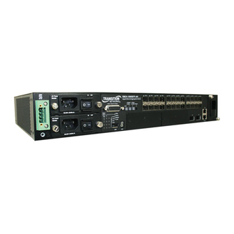
Transition Networks SM24-1000SFP-AH Manuals
Manuals and User Guides for Transition Networks SM24-1000SFP-AH. We have
1
Transition Networks SM24-1000SFP-AH manual available for free PDF download: Installation Manual
Transition Networks SM24-1000SFP-AH Installation Manual (76 pages)
Gigabit Ethernet Switch
Brand:
Transition Networks
| Category:
Switch
| Size: 3 MB
Table of Contents
Safety Compliance
6
Power Cord Safety
7
Warnings and Cautionary Messages
10
End of Product Life Span
11
Manufacturing Materials
11
Related Publications
11
Table of Contents
13
Chapter 1: Introduction
19
Overview
19
Figure 1-1 Front Panel
19
Network Management Options
20
Switch Architecture
20
Description of Hardware
20
SFP Slots
20
XFP Slots
21
100BASE-TX Management Port
21
Console Port
21
Alarm Interface Port
21
Figure 1-2 Single-Port 10GBASE Module (XFP)
21
Port and System Status Leds
22
Table 1-1 Port and System Status Leds
22
Figure 1-3 Port and System Leds
22
Fan Tray
23
Figure 1-4 Fan Tray
23
Power Modules
24
Features and Benefits
24
Connectivity
24
Expandability
24
Figure 1-5 Optional Power Modules
24
Performance
25
Management
25
Chapter 2: Network Planning
27
Fiber-To-The-Home (FTTH)
27
Connection Examples
28
Downlink Fiber Connections
28
Figure 2-1 Downlink Fiber Connections
28
Uplink Connections
29
Figure 2-2 Uplink Fiber Connections
29
Management Connections
30
Figure 2-3 Management Port Connections
30
Private VLAN Connections
31
Figure 2-4 Private VLAN Connections
31
Application Notes
32
Chapter 3: Installing the Switch
33
Selecting a Site
33
Ethernet Cabling
33
Equipment Checklist
34
Package Contents
34
Optional Rack-Mounting Equipment
34
Figure 3-1 RJ-45 Connections
34
Mounting
35
Rack Mounting
35
Figure 3-2 Attaching the Brackets
35
Desktop or Shelf Mounting
36
Figure 3-3 Installing the Switch in a Rack
36
Figure 3-4 Attaching the Adhesive Feet
36
Installing an Optional Module into the Switch
37
Figure 3-5 Installing an Optional Module
37
Installing an Optional SFP/XFP Transceiver
38
Figure 3-6 Inserting an SFP/XFP Transceiver into a Slot
38
Grounding the Chassis
39
Connecting to a Power Source
39
Connecting DC Power
39
Figure 3-7 DC Plug Connections
40
Connecting AC Power
41
Figure 3-8 AC Power Receptacle
41
Connecting to the Console Port
42
Wiring Map for Serial Cable
42
Table 3-1 Serial Cable Wiring
42
Figure 3-9 Serial Port (RJ-45) Pin-Out
42
Connecting to the Alarm Port
43
Wiring Map for Alarm Cable
43
Table 3-2 Alarm Cable Wiring
43
Figure 3-10 Alarm Port (D-15) Pin-Out
43
Figure 3-11 External Alarm I/O Connections
44
Chapter 4: Making Network Connections
45
Connecting Network Devices
45
Twisted-Pair Devices
45
Cabling Guidelines
45
Connecting to Pcs, Servers, Hubs and Switches
46
Gbps Fiber Optic Connections
46
Figure 4-1 Making Twisted-Pair Connections
46
Figure 4-2 Making Connections to SFP Transceivers
47
Gbps Fiber Optic Connections
48
Connectivity Rules
49
1000BASE-T Cable Requirements
49
Figure 4-3 Connecting to an XFP Transceiver
49
10 Gbps Ethernet Collision Domain
50
1000 Mbps Gigabit Ethernet Cable Lengths
50
Table 4-1 Maximum 10GBASE-SR 10 Gigabit Ethernet Cable Length
50
Table 4-2 Maximum 10GBASE-LR 10 Gigabit Ethernet Cable Length
50
Table 4-3 Maximum 10GBASE-ER 10 Gigabit Ethernet Cable Length
50
Table 4-4 Maximum 1000BASE-T Gigabit Ethernet Cable Length
50
Table 4-5 Maximum 1000BASE-SX Gigabit Ethernet Cable Length
50
Table 4-6 Maximum 1000BASE-LX Gigabit Ethernet Cable Length
50
100 Mbps Fast Ethernet Cable Lengths
51
10 Mbps Ethernet Cable Lengths
51
Cable Labeling and Connection Records
51
Table 4-7 Maximum 1000BASE-LH Gigabit Ethernet Cable Length
51
Table 4-8 Maximum 1000BASE-BX10-U Gigabit Ethernet Cable Length
51
Table 4-9 Maximum Fast Ethernet Cable Length
51
Table 4-10 Maximum Ethernet Cable Length
51
Appendix A: Troubleshooting
53
Diagnosing Switch Indicators
53
Table A-1 Troubleshooting Chart
53
Power and Cooling Problems
54
Installation
54
In-Band Access
54
Figure
54
Appendix B: Cables
55
Twisted-Pair Cable and Pin Assignments
55
10BASE-T/100BASE-TX Pin Assignments
55
Figure B-1 RJ-45 Connector Pin Numbers
55
Straight-Through Wiring
56
Table B-1 10/100BASE-TX MDI and MDI-X Port Pinouts
56
Figure B-2 Straight-Through Wiring
56
Crossover Wiring
57
Figure B-3 Crossover Wiring
57
1000BASE-T Cable Requirements
58
1000BASE-T Pin Assignments
58
Table B-2 1000BASE-T MDI and MDI-X Port Pinouts
58
Cable Testing for Existing Category 5 Cable
59
Adjusting Existing Category 5 Cabling to Run 1000BASE-T
59
Fiber Standards
59
USB Cabling
60
Table B-3 USB Port Pinouts
60
Appendix C: Specifications
61
Physical Characteristics
61
Switch Features
62
Management Features
62
Standards
63
Compliances
63
Extender Modules
64
Gigabit Extender Module (XFP
64
Glossary
65
Index
71
Advertisement
Advertisement
Related Products
Transition Networks SM24-100SFP-AH
Transition Networks SM24DPa
Transition Networks SM24TAT4GPA
Transition Networks SM24TAT4XA
Transition Networks SM24TAT2DPA
Transition Networks SM24TAT2SA
Transition Networks SM24DPB
Transition Networks SM24TBT2DPA
Transition Networks SM24DP4XA
Transition Networks SM24TAT4XB
Transition Networks Categories
Media Converter
Switch
Transceiver
Power Supply
Chassis
More Transition Networks Manuals
Login
Sign In
OR
Sign in with Facebook
Sign in with Google
Upload manual
Upload from disk
Upload from URL