
Related Manuals for Intuicom RTK Bridge

Summary of Contents for Intuicom RTK Bridge
-
Page 1: User Guide
Intuicom ® Wireless RTK Bridge - Cellular User Guide Intuicom, Inc. 1880 S Flatiron Court Boulder, CO 80301 (303) 449-4330 www.intuicom.com... - Page 2 Intuicom reserves the right to make changes to this manual without notice. Unless otherwise agreed to in writing, Intuicom assumes no responsibility or liability for the use of this manual or for the infringement of any copyright or other proprietary right and Intuicom shall deem nothing contained in this manual a warranty or guarantee.
- Page 3 Wireless RTK Bridge – Cellular User Guide This product is licensed by The United States. Diversion contrary to U.S. law is prohibited. Shipment or re-export of this product outside of The United States may require authorization by the U.S. Bureau of Export Administration. Please contact Intuicom, Inc.
-
Page 4: Table Of Contents
Wireless RTK Bridge – Cellular User Guide Table of Contents Overview ..........................1 Key Features ........................1 Front Panel Connectors and Controls ................2 Example Applications ..................... 3 Initialization and Configuration ..................6 ... -
Page 5: Overview
The Intuicom Wireless RTK Bridge - Cellular expands access to GNSS network RTK corrections for rover users in the field. The RTK Bridge - Cellular combines an embedded GPS and cellular (CDMA or GSM/GPRS/EDGE) Internet connectivity with an Intuicom Wireless Data Radio with to support a wide range of deployment configurations. -
Page 6: Front Panel Connectors And Controls
(6) Power On/Off Button (7) TNC antenna connector for internal CDMA/GSM/GPRS/EDGE modem (8) TNC antenna connector for internal L1 GPS (9) TNC antenna connector for internal Intuicom 900 MHz Wireless Data Radio or other embedded data radio Revision 1.4 © 2009 Intuicom, Inc. -
Page 7: Example Applications
Typical installations have the RTK Bridge configured to connect to an NTRIP Caster where it provides mountpoint and authentication information. Once connected to a mountpoint, it will stream its GPS point position (from its internal L1 GPS) allowing the Network Correction Server (such as Leica Spider) to generate individualized corrections or create a virtual reference station. - Page 8 Topcon, etc. Figure 1-3: Intuicom RTK Bridge - Cellular used with third party base radio Leveraging Existing Data Radios - The Intuicom Wireless RTK Bridge can be used to supplement and existing wireless network, replacing the local base station GPS. Users simply connect a third party base radio to the Data Out port on the front of the unit to broadcast a copy of the correction stream.
- Page 9 Bridge. Furthermore, if the distance between the RTK Bridge and the rover users is great – the RTK Bridge can be configured to report its position to the GNSS Network server as if it were in the location of the rovers – further optimizing the network correction generated by the GNSS network server.
-
Page 10: Initialization And Configuration
Section 2: Initialization and Configuration 2 Initialization and Configuration Prior to the first use of the Intuicom RTK Bridge must be activated and configured. A onetime process of activation is required to setup the integrated CDMA or GSM cellular modem for use on the chosen carrier’s network. - Page 11 19200 baud, 8 data bits, 1 stop bit, no parity, and no flow control: Figure 2-2: Hyperterminal Connection Properties Dialog 3. Power the RTK Bridge unit by pressing and holding the green power button until the PWR LED turns red. Wait for approximately 30 seconds for the unit to boot, then type “700”...
- Page 12 Section 2: Initialization and Configuration Figure 2-3: RTK Bridge Initial Startup Output Figure 2-4: RTK Bridge Main Configuration Menu 4. You are now ready to interact with the configuration menus. Pressing the ESC key at the top level menu will exit the menu and the unit will restart and begin running using the currently selected PROFILE configuration parameters.
-
Page 13: Embedded Cellular Modem Activation
Currently the Intuicom RTK Bridge - Cellular can be ordered with an embedded modem compatible with either Verizon (CMDA) or any GSM/GPRS/EDGE carrier such as AT&T or T-Mobile. - Page 14 Section 2: Initialization and Configuration Figure 2-6: Example Verizon Embedded Modem Configuration Screen Figure 2-7: Example GSM/GPRS/EDGE Embedded Modem Configuration Screen Revision 1.4 © 2009 Intuicom, Inc.
-
Page 15: Verizon Service (Us Customers)
This plan is a 5GB/month data only plan for a fixed monthly price. Note: used 24x7 with a 1 Hz RTCM3 correction, an RTK Bridge should use ~ 2GB/month of data. The representative will provide a 10-digit phone number (MDN) – record this number, you will be prompted to enter it during the provisioning step. - Page 16 Section 2: Initialization and Configuration The activation process takes approximately one to two minutes to complete. Success or failure will be displayed on the screen after the process is complete. Figure 2-8: Successful Verizon Activation Revision 1.4 © 2009 Intuicom, Inc.
-
Page 17: Gsm/Gprs/Edge Service
USA) to establish and account and/or add a line of service for this device. Most carriers have a basic data plan with a 5GB/month data limit. Note: used 24x7 with a 1 Hz RTCM3 correction, an RTK Bridge should use ~ 2GB/month of data. Carrier... - Page 18 PIN number entered. Use caution in entering the PIN number. The RTK Bridge will test the PIN after it has been entered to confirm it is correct. The RTK Bridge will attempt to avoid exceeding the maximum number of PIN attempts if an incorrect PIN has been entered (for example, the SIM card has been swapped, but the PIN not updated).
- Page 19 Section 2: Initialization and Configuration Username Password SIM Pin Figure 2-9: GPRS/EDGE APN, Username, and Password Parameters Revision 1.4 © 2009 Intuicom, Inc.
-
Page 20: Configuration Process
The Intuicom RTK Bridge can store one set of the above parameters for each of four Profiles – allowing the user to select the configuration set to use in the field without the need for a PC and terminal program. - Page 21 Be carefully to enter the IP address correctly. Server Port – Enter the TCP port number on the GNSSnetwork server to connect to. Typically the TCP port number will have been provided with the server IP address. Revision 1.4 © 2009 Intuicom, Inc.
- Page 22 GNSS network server to be able to generate a stream of network RTK corrections specific for the user’s location. In most cases the distance between the RTK Bridge’s GPS antenna and the rover user(s) position is both not great, and not significant in generating the correction stream.
- Page 23 Section 2: Initialization and Configuration Internal Radio – The internal Intuicom 900MHz spread spectrum data radio can be enabled or disabled. If enabled, the user can configure and specify which channel to use. This radio is fully compatible with Intuicom 1200 Data Link radios, as well as Intuicom Communicator II radios.
- Page 24 Repeaters Enabled parameter to be able to communicate. It is recommended to leave the default value of Yes unless a specific application dictates otherwise. Contact Intuicom for more information about configuring repeaters.
- Page 25 Section 2: Initialization and Configuration PROFILE PARAMETER Mode (RAW/NTRIP) Server IP Server TCP Port Mountpoint Name Authentication Username Password GPS Mode Latitude Longitude Internal Radio Enabled Internal Radio Channel Data Port Baud Table 2-2: Profile Configuration Table Revision 1.4 © 2009 Intuicom, Inc.
-
Page 26: Administrative
Internal Radio Advanced Configuration - Select this option for access to Advanced Wireless configuration. The Advanced wireless configuration allows the internal wireless data radio to be fine tuned for compatibility with a range of Intuicom Wireless Data Transceiver products, and for specific wireless configuration to address a location specific condition (like lowering the transmit power, or avoiding in-band interference). - Page 27 APN. It is recommended not to change any of these parameters from their defaults. Upgrade RTK Bridge Firmware – This option allows the unit’s base firmware to be upgraded or downgraded. Contact Intuicom for the latest firmware and the firmware upgrade utility.
-
Page 28: Operation
Section 3: Operation 3 Operation The Intuicom Wireless RTK Bridge unit must be properly configured before operation. See Section 2 for information about how to configure a unit prior to use. Once configured, and physically setup for operation, the unit will go through a startup routine when powered on, connect to the GNSS network server, and begin broadcasting corrections. - Page 29 RTK Bridge to external radio cables. CAUTION: Only apply power from one source! Connect 10-24 VDC power to the front panel using the included power adapter or using the optional power pigtail.
- Page 30 Intuicom 900MHz 5dB Omni Antenna Intuicom 900 MHz Spread Spectrum Wireless Data LMR240 Coax Directional Cellular/3G Duck Antenna CDMA/GSM/EDGE Intuicom RTK Wireless Connection Bridge - Cellular Battery Figure 3-3: Typical RTK Bridge field setup Revision 1.4 © 2009 Intuicom, Inc.
-
Page 31: Startup Sequence
8. The TXD LED will begin to blink as corrections are received and broadcast out the internal data radio and/or the Data port on the front panel. Operation will continue until interrupted by power off, or loss of cellular signal. Revision 1.4 © 2009 Intuicom, Inc. -
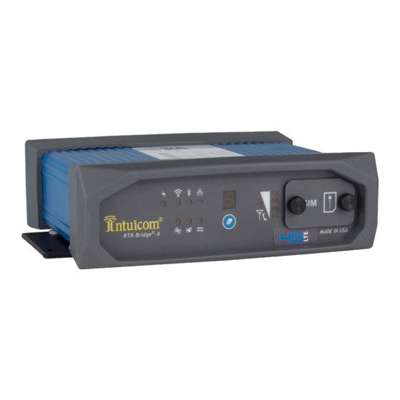
Page 32: Front Panel Leds
Front Panel LEDs There are eleven red LEDs visible on the front panel (5) and (4). Figure 3-4: RTK Bridge - Cellular Front Panel PWR – When illuminated indicates that the unit is powered and has been turned on. GPS:... - Page 33 MDM – Indicates a successful connection to the carrier’s IP network (and thus the Internet) SVR – Indicates a successful network connection to the IP socket (either RAW or NTRIP). TXD – Indicates data being transmitted out the internal Intuicom Wireless Data Radio, and/or the Data port (2) on the front panel.
-
Page 34: Config Port Status Display/Messages
• Status of data received from the server or NTRIP Caster, and its broadcast on the wireless network. The following screenshots provide example status messages: Figure 3-5: Example status message output on Config Port Revision 1.4 © 2009 Intuicom, Inc. - Page 35 Section 3: Operation Figure 3-6: Example status message output on Config Port Revision 1.4 © 2009 Intuicom, Inc.
-
Page 36: Antenna Aiming / Cellular Signal Strength Mode
Section 3: Operation Antenna Aiming / Cellular Signal Strength Mode The RTK Bridge - Cellular has a special mode useful when utilizing a directional antenna for the embedded Cellular modem. A directional antenna is most useful when operating in an area of weak cellular coverage. -
Page 37: Changing Profiles
NTRIP mountpoint names. The user wants to be able to switch from an RTCM 3 correction to a Leica message from a specific reference station. The user can change the RTK Bridge to use the different profile, and change the rover configuration to accept the different correction message type. -
Page 38: Optimizing Wireless Performance
Height is everything. If the RTK Bridge and antenna setup can be located at a high-point that improves line of sight between its antenna and rover units, the performance can be greatly improved. - Page 39 4) Rover antenna type and condition – confirm that the rover users are using the correct antenna. Any additional height that can be added to the rover antenna is useful – such as a backpack with a short pole and adapter for the duck antenna. Revision 1.4 © 2009 Intuicom, Inc.
-
Page 40: Connecting To Third-Party Radio
RS232. To connect to an external third-party radio: 1. Configure the baud rate of the DATA port on the RTK Bridge to match the baud rate of the third-party radio. 2. Connect the included Data/Power cable to the Data port on the front of the unit. -
Page 41: Troubleshooting
Confirm an active SIM is inserted and APN parameters correctly configured. SVR LED never lights Unit unable to establish TCP Configure Server IP Address and socket connection to server - Port Incorrect Server Address or Port Configuration Revision 1.4 © 2009 Intuicom, Inc. - Page 42 Rover GNSS unit and/or the for the Rover GNSS unit mountpoint from the GNSS Server Remote RTK Rover units unable to Channel Configuration incorrect Confirm both the RTK Bridge and establish link via wireless embedded Wrong channel selected Rovers have channel configurations radio...
-
Page 43: Accessories
Auto Power Adapter Standard Auto ligher adapter to ASE power plug FIP4-SAECIG Cable Assembly-RTK Cable assembly to connect RTK Bridge C to a Pacific Crest 35W PDL, includes power inputs to both units, Lemo to Lemo connection Bridge to 35W Pacific FIP4-RTKCAB-PC35... - Page 44 Dual mode, hi-gain cellular-GPS stud (through-hole) mount antenna FIP4-SMDM-MAX-ANT assembly, TNC connnectors, 15-foot length stud mount Cable assembly to connect RTK Bridge C to a 3rd party GPS device, Cable Assembly-RTK Lemo to unfinnished connection, 15-foot length. Bridge to 3rd Party...
-
Page 45: Technical Support
Section 6: Technical Support 6 Technical Support Contact Intuicom: email: support@intuicom.com phone: 303-449-4330 – request technical support for the RTK Bridge - Cellular. Revision 1.4 © 2009 Intuicom, Inc. -
Page 46: Fcc Notification
This device must be operated as supplied by Intuicom, Inc. Any changes or modifications made to the device without the express written approval of Intuicom may void the user's authority to operate the device. -
Page 47: Warranty
Hardware, and functional failure, improper operation, failure to operate according to specifications or any other matter related to the Hardware. INTUICOM shall not be liable or responsible for the failure of the Manufacturer to perform under or honor any warranty with respect to the Hardware.
Need help?
Do you have a question about the RTK Bridge and is the answer not in the manual?
Questions and answers