Table of Contents
Advertisement
Quick Links
Advertisement
Table of Contents
Troubleshooting

Related Manuals for GeoVision GV-Hot Swap DVR System V4


Summary of Contents for GeoVision GV-Hot Swap DVR System V4
- Page 1 GV-Hot Swap DVR System V4 User’s Manual User’s Manual...
- Page 2 Under the copyright laws, this manual may not be copied, in whole or in part, without the written consent of GeoVision. Every effort has been made to ensure that the information in this manual is accurate. GeoVision is not responsible for printing or clerical errors.
- Page 3 Chapter 4, DVR Health Analysis Introduces how to collect data to obtain the service of DVR health analysis from GeoVision. • Chapter 5, Troubleshooting Suggests courses of action if the GV-Hot Swap DVR System V4 doesn’t seem to be working properly.
-
Page 4: Table Of Contents
Contents Regulatory Notices ....................iv Safety Instructions ....................v Chapter 1 Introduction................... 1 1.1 Models ........................1 1.2 Unpacking......................... 2 1.3 Options ........................4 Chapter 2 Overview ....................6 2.1 Front View ........................ 6 2.1.1 20-Bay Models ....................6 2.1.2 8-Bay Models ....................7 2.1.3 2-Bay Models ....................7 2.2 LED Panel View...................... - Page 5 3.4 Formatting the Hard Drive ..................26 3.5 Adding the Hard Drive to the Recording Path ............33 3.6 Setting Up On-Screen LED Panel ................35 3.7 Replacing the Hard Drive ..................37 3.7.1 20-Bay Models ..................37 3.7.2 8 / 4 / 2-Bay Models ..................37 3.8 Configuring an IP Address..................
-
Page 6: Regulatory Notices
Regulatory Notices FCC Notice This equipment has been tested and found to comply with the limits for a Class A digital device, pursuant to part 15 of the FCC Rules. These limits are designed to provide reasonable protection against harmful interference when the equipment is operated in a commercial environment. -
Page 7: Safety Instructions
Safety Instructions Observe these safety instructions to help ensure against injury to yourself and damage to the product. all safety and installation instructions before you operate the product. Read the product in high humidity areas or expose it to water or moisture. Do not operate the product in an unstable, a slanting or vibrated place. -
Page 9: Chapter 1 Introduction
GV IP channels and third-party IP channels you need. - Has the option of 2 / 4 / 8 / 20 hot-swap SATA drive bays - Extends compatibility to GeoVision and third-party IP devices Note: 1. The 2-bay and 20-bay models of GV-Hot Swap DVR V4 are available upon special request with longer lead time. -
Page 10: Unpacking
1.2 Unpacking The GV-Hot Swap DVR V4 package includes the following items. Important: Please keep the original carton and all packing materials for future shipping need. 1. GV-Hot Swap DVR V4 x 1 2. D-Type Video Cable x 2 * D-Type Video Cable x 4 for 32-channel models ONLY supplied with 20-bay models of GV-1480H V4, GV-1240H V4 and GV-1120H V4 *... - Page 11 15. GV-IR Remote Control User’s Manual x 1 16. GV-Hot Swap DVR System V4 User’s Manual x 1 17. GV-Hot Swap DVR System V4 Quick Start Guide x 1 18. Surveillance System New Feature Guide x 1 19. Surveillance System Installation Guide x 1...
-
Page 12: Options
1.3 Options Optional devices can expand your GV-Hot Swap DVR V4’s capabilities and versatility. Contact your dealer for more information. This card can take the video signal from the GV-Hot Swap DVR GV-Video Loop Through V4 and then split it into 16 signals while maintaining video Card *... - Page 13 Introduction However, this device can only work on GV-System version 8.2 or later. The RAID Controller supports a maximum of 8 SATA hard RAID Controller drives and enhances data protection. The supported RAID (0 / 1 / 5 / 6) types include RAID 0, RAID 1, RAID 5 and RAID 6.
-
Page 14: Chapter 2 Overview
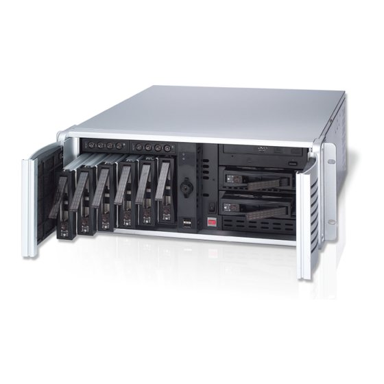
Chapter 2 Overview 2.1 Front View 2.1.1 20-Bay Models Figure 2-1 No. Name Name USB Port x 2 Reset Button LED Panel DVD(±) RW Drive (See 2.2 LED Panel View for details.) DVD(±) RW Drive Activity LED HDD Group A DVD-eject button HDD Group B Built-in GV-IR Remote Control... -
Page 15: 8-Bay Models
Overview 2.1.2 8-Bay Models Figure 2-2 For details on the other features of the front panel, see Figure 2-1. 2.1.3 2-Bay Models Figure 2-4 For details on the other features of the front panel, see Figure 2-1. -
Page 16: Led Panel View
2.2 LED Panel View A LED panel on the front door provides a quick indication of the activity status of hard disk drives. Note the panel design and function vary from model to model. 2.2.1 20-Bay Models Figure 2-5 No. LED Description Power LED The LED shines when the power is on. -
Page 17: 4-Bay Models
Overview 2.2.2 8 / 4-Bay Models LED Panel Figure 2-6 LED Color Description - No HDD is assigned to this LED. Gray - GV-System is not started. Green A HDD is assigned to this LED. The HDD is full. GV-System is recording or the video / audio files are played Flashing Green back with ViewLog. -
Page 18: Rear View
2.3 Rear View 2.3.1 20-Bay Models 2.3.1.1 GV-2016H V4 / GV-2008H V4 Figure 2-7 No. Name No. Name AC Power Switch Audio Line In Port AC Power Input (Full Range) Audio Line Out Port PS/2 Mouse Input Audio Microphone In Port I/O and RS-485±Terminal Block PS/2 Keyboard Input USB Port x 2... -
Page 19: Gv-1480H V4 / Gv-1240H V4 / Gv-1120H V4 (32 Channels)
Overview 2.3.1.2 GV-1480H V4 / GV-1240H V4 / GV-1120H V4 (32 Channels) Figure 2-8 No. Name No. Name VGA Monitor Output VGA Monitor Output I/O and RS-485±Terminal Block S-Video Output RJ-11 Port DVI-I Output RCA TV Output 1-16 D-Type Audio 1-8 D-Type Video 1-8 D-Type Audio 9-16 D-Type Video 9-16... -
Page 20: Gv-1480H V4 / Gv-1240H V4 / Gv-1120H V4 (16 Channels)
2.3.1.3 GV-1480H V4 / GV-1240H V4 / GV-1120H V4 (16 Channels) Figure 2-9 No. Name No. Name VGA Monitor Output D-Type Video 1-8 DVI-D Output D-Type Video 9-16 I/O and RS-485±Terminal Block D-Type Audio 1-8 RJ-11 Port D-Type Audio 9-16 RCA TV Output 1-16 Note: To connect to two monitors, use the ports No. -
Page 21: Gv-Nvrh V4
Overview 2.3.1.4 GV-NVRH V4 Figure 2-10 For details on the other features of the motherboard and power supply on the rear panel, see Figure 2-7. -
Page 22: 4-Bay Models
2.3.2 8 / 4-Bay Models 2.3.2.1 GV-2016H V4 / GV-2008H V4 Figure 2-11 No. Name No. Name AC Power Input (Full Range) Ethernet Port x 2 AC Power Switch USB Port x 4 I/O and RS-485± Terminal Block Center/Subwoofer Port RJ-11 Port Rear R/L Port D-Type Audio 1-16... -
Page 23: Gv-1480H V4 / Gv-1240H V4 / Gv-1120H V4 (32 Channels)
Overview 2.3.2.2 GV-1480H V4 / GV-1240H V4 / GV-1120H V4 (32 Channels) Figure 2-12 No. Name No. Name D-Type Audio 1-8 D-Type Video 17-24 D-Type Audio 9-16 D-Type Video 25-32 I/O and RS-485±Terminal Block D-Type Audio 17-24 D-Type Audio 25-32 RJ-11 Port VGA Monitor Output VGA Monitor Output... -
Page 24: Gv-1480H V4 / Gv-1240H V4 / Gv-1120H V4 (16 Channels)
2.3.2.3 GV-1480H V4 / GV-1240H V4 / GV-1120H V4 (16 Channels) Figure 2-13 No. Name No. Name I/O and RS-485±Terminal Block RCA TV Output RJ-11 Port VGA Monitor Output D-Type Audio 1-16 DVI-D Output BNC Video Connector x 16 Not recommended for use *... -
Page 25: 2-Bay Models
Overview 2.3.3 2-Bay Models 2.3.3.1 GV-2008H V4 / GV-1480H V4 / GV-1240H V4 / GV-1120H V4 Figure 2-15 For details on the other features of the motherboard and power supply on the rear panel, see Figure 2-11. 2.3.3.2 GV-NVRH V4 Figure 2-16 For details on the other features of the motherboard and power supply on the rear panel, see Figure 2-11. -
Page 26: Chapter 3 Getting Started
Chapter 3 Getting Started 3.1 Basic Installation This section describes all the equipments required to program and operate the GV-Hot Swap DVR V4. Depending on the models, 2 or 3 monitors can be connected to the GV-Hot Swap DVR V4. Here we use the 8 / 4-bay model (16 channels) as the example. -
Page 27: Connecting To 2 Monitors
Getting Started 3.1.1 Connecting to 2 Monitors For users of the models that can connect up to 2 monitors, please see the figure below to connect the monitors to the GV-Hot Swap DVR V4. The available models include GV-NVRH V4, GV-2008H V4, and GV-1480H V4 / GV-1240H V4 / GV-1120H V4 (16 Channels). Here we use the 8 / 4-bay model (16 channels) as the example. -
Page 28: Connecting To 3 Monitors
3.1.2 Connecting to 3 Monitors For users of the models that can connect up to 3 monitors, please see the figure below to connect the monitors to the GV-Hot Swap DVR V4. The available models include GV-2016H V4, GV-1480H V4 / GV-1240H V4 / GV-1120H V4 (32 Channels). Here we use the 8 / 4-bay model (32 channels) as the example. -
Page 29: Turning On The Power
Getting Started 3.2 Turning on the Power Once the above hardware is properly connected, it is the time to turn on the GV-Hot Swap DVR V4. To turn on the power, follow these steps: 1. Turn on the monitor. Figure 3-4 2. - Page 30 2. For 20-bay models, the Power LED and the LEDs of HDD Group A to HDD Group D should shine after power is on. If any of HDD Group LEDs does not shine, please contact GeoVision.
-
Page 31: Installing The Hard Drive
Getting Started 3.3 Installing the Hard Drive The GV-Hot Swap DVR V4 uses SATA hard drives for video and audio data storage. Before recording, ensure to install your hard drives. Steps to install the hard drive vary from models to models. -
Page 32: / 2-Bay Models
3.3.2 8 / 4 / 2-Bay Models 1. Turn off the power of the drive bay. Make sure the Power LED is off. 2. Turn the safety lock to the OPEN position. 3. Push the safety lock. The drawer handle pops up. 4. -
Page 33: Getting Started
Getting Started 5. Remove the lid of the drawer. Figure 3-13 6. Insert the hard drive in the drawer, and slide the lid back on. Figure 3-14 7. Turn over the drawer, and secure the hard drive with the 4 screws (included in the drawer). Figure 3-15 8. -
Page 34: Formatting The Hard Drive
3.4 Formatting the Hard Drive After installing hard drives to your GV-Hot Swap DVR V4, you may need to format them before use. 1. On the GV-Desktop, click the Programs button, and select Disk Management. Figure 3-16 2. Type the ID and password in the dialog box. The default ID and password are “0000”. Figure 3-17... - Page 35 Getting Started 3. The Initialize and Convert Disk Wizard appears. Click Next to continue. Figure 3-18 Note: If the Wizard does not appear, you need to initialize the drives one by one. To manually initialize a drive, right-click on the name of the drive and select Initialize Disk. 4.
- Page 36 5. The screen gives you the option to convert the drives from basic to dynamic storage. Leave all drives unchecked, and click Next to continue. Figure 3-20 6. When the initialization is complete, click Finish to close the wizard. Figure 3-21...
- Page 37 Getting Started 7. Right-click in the unallocated space of a new drive, and select New Partition. Figure 3-22 8. The New Partition Wizard appears. Click Next to continue. Figure 3-23...
- Page 38 9. Select Primary partition, and click Next to continue. Figure 3-24 10. The default partition size is the same as the maximum disk space. Make changes if necessary. Click Next to continue. Figure 3-25...
- Page 39 Getting Started 11. Assign a drive path that is not in use by other devices, and click Next to continue. Figure 3-26 Note: The default drive path starts from F:\. 12. Type a name in the Volume label box, ex. HDD1, and click Next to continue. Figure 3-27...
- Page 40 13. When the formatting is complete, click Finish to close the wizard. Figure 3-28 14. When the drive is successfully initialized, partitioned, and formatted, its status description should display “Healthy.” Figure 3-29...
-
Page 41: Adding The Hard Drive To The Recording Path
Getting Started 3.5 Adding the Hard Drive to the Recording Path Before recording, you need to add the formatted hard drives to the recording path. 1. On the GV-Desktop, click the Programs button, and select Hot Swap HDD Tool. The MediaMan Tools window appears. - Page 42 B. Select Add to recording path, and select the storage group from the drop-down list. Note: Storage 1 is the default storage group. 4. Click OK to automatically configure the hard drive to the recording path. 5. In the Median Man Tools window, if the hard drive is successfully added to store data, its Status field should display “Standby”.
-
Page 43: Setting Up On-Screen Led Panel
Getting Started 3.6 Setting Up On-Screen LED Panel A LED panel on the screen provides a quick indication of the activity status of hard disk drives. Figure 3-33 LED Color Description - No HDD is assigned to this LED. Gray - GV-System is not started. - Page 44 LED Panel always stays on top: This option makes the LED panel stay on top of other windows when the Media Man Tools window is minimized. Synchronize the LED Panel with the LED Device on GV-Hot Swap DVR: When this option is enabled, the LED device installed on the front door of the GV-Hot Swap DVR V4 will synchronize with the LED panel on the screen.
-
Page 45: Replacing The Hard Drive
Getting Started 3.7 Replacing the Hard Drive You can replace the hard drive in the Hot Swap Drive Bay without shutting down the GV-Hot Swap DVR V4. Steps to replace the hard drive may vary from models to models. Be sure to identify your model before replacing the hard drive. -
Page 46: Configuring An Ip Address
3.8 Configuring an IP Address The purpose of configuring an IP address is to support the remote monitoring, control and configuration of the GV-Hot Swap DVR V4 over a network connection. The GV-Hot Swap DVR V4 is enabled for DHCP network. An IP address will be automatically allocated when the GV-Hot Swap DVR V4 is powered up. - Page 47 Getting Started 3. Double-click Network Connections, right-click Local Area Connection, and then select Properties. Figure 3-37 4. In the Local Area Connection Properties dialog box, select Internet Protocol (TCP/IP) and then click Properties. Figure 3-38 5. Select Use the following IP address, type the IP information in the fields, and click OK to finish the setting.
-
Page 48: Exiting To Windows
3.9 Exiting to Windows The unit is protected by GV-Desktop that is limited to run the selected programs. If you need to exit to Windows desktop, follow these steps. 1. Exit the main screen to display the GV-Desktop screen. Figure 3-40 Exit the main screen 2. -
Page 49: Returning To Gv-Desktop
Getting Started 3.10 Returning to GV-Desktop Click the Windows Start button, point to All Programs, click GVCombo, and click Key Lock Utility. Figure 3-42 Windows XP desktop... -
Page 50: Twin View Display
3.11 Twin View Display You can display Main System and ViewLog in two separated monitors. 1. Follow Steps 1 and 2 in 3.8 Configuring an IP Address to access the Control Panel window. See Figure 3-36. 2. In the Control Panel window, double-click Display and then click the Settings tab. Figure 3-43 3. - Page 51 Getting Started Figure 3-44 9. Double-click DMPOS.exe. The Set Application Function Position dialog box appears. Figure 3-45 10. In the Screen Setup tab, select TwinView from the Displayer Mode drop-down list. 11. In the MultiCam tab, select Monitor 1 from the Select Monitor drop-down list. 12.
-
Page 52: Digital Matrix
3.12 Digital Matrix To create more screen space to display multiple channels, such as 32 channels, Digital Matrix is thus introduced to provide a way to view and manage multiple monitor displays. The Digital Matrix includes these features: Live view: You can set different live views and screen divisions for each monitor. Automatic channel scan: You can set up to 16 scanned pages with different screen divisions and channels for each monitor. -
Page 53: Setting Live View
Getting Started 3.12.2 Setting Live View You can set different live views and screen divisions for each monitor. 1. On the main screen, click the Configure button, click Accessories, and select Digital Matrix Setting. This dialog box appears. Figure 3-46 2. -
Page 54: Setting Scanned
3.12.3 Setting Scanned Pages You can set up to 16 scanned pages with different screen divisions and channels for each monitor. 1. Use the Display list to select the monitor to be configured. 2. In the upper-left column, expand the Matrix folder tree, and then click Page 1. This page appears. -
Page 55: Setting Pop-Up Alert
Getting Started 3.12.4 Setting Pop-up Alert You can be alerted by pop-up live videos when motion is detected or I/O devices are triggered. 1. Use the Display list to select the monitor to be configured. 2. In the upper-left column, click Event Popup. This page appears. Figure 3-48 Motion Trigger: The live video of selected cameras pops up when motion is detected. -
Page 56: Setting Pop-Up Positions
3.12.4.1 Setting Pop-up Positions When you select Random Position of Camera, you can decide the positions for pop-up cameras. Fixed Position of Camera: The cameras pop up in their assigned positions. To assign positions, select Screen Division. Then drag and drop the cameras number to the desired potions on the divisions. -
Page 57: Setting Live View With Pop-Up Alert
Getting Started 3.12.5 Setting Live View with Pop-up Alert You can set a different live view mode with pop-up alert together for each monitor. When alert events occur, the live video of the associated camera will pop up on the assigned monitor to replace its live view mode. -
Page 58: Limited Use Of Digital Matrix
3.12.6 Limited Use of Digital Matrix For the models of GV-Hot Swap DVR V4 series providing 32-channel view display, using Digital Matrix may decrease the frame rate and affect recording quality. By the combination of codec and resolution, here we list what screen divisions should be set on the monitors when Digital Matrix is in use. - Page 59 Getting Started The maximum number of screen divisions allowed on both monitor 2 (#2) and monitor 3 (#3) are listed in the following tables. GV-1480H V4 (32 Channels) Unit: Divisions Codec MPEG 4 MPEG4 ASP H.264 H.264 V2 Monitor Monitor Monitor Monitor Resolution...
-
Page 60: Extended Installation
3.13 Extended Installation Beyond basic installation, the GV-Hot Swap DVR V4 package provides the following accessories to make your unit even more powerful and convenient: GV-Keyboard GV-IR Remote Control RJ-11 to DB9 Cable for PTZ control Note: The RJ-11 to DB9 Cable is not available for GV-NVRH V4 and all 2-bay models. 3.13.1 GV-Keyboard The GV-Keyboard is designed to operate the GV-Hot Swap DVR V4 exclusively. -
Page 61: Gv-Ir Remote Control
Getting Started To modify the default COM port: 1. Click to stop the Keyboard service first. 2. In the Port field, modify the port number from the drop-down list. For the port allocation, refer to Figure 3-50-2. 3. Click to start the service. USB &... -
Page 62: I/O Devices
3.13.3 I/O Devices The GV-Hot Swap DVR V4, with built-in GV-NET/IO Card, provides 4 alarm outputs and 4 sensor inputs. 20-Bay Models Relay Output 1~4 Sensor Input 1~4 Ground Figure 3-52 8 / 4-Bay Models Relay Output 1~4 Sensor Input 1~4 Ground Figure 3-53... -
Page 63: Ptz Domes
Getting Started 3.13.4 PTZ Domes When connecting PTZ domes, you need to plug the supplied RJ-11 to USB cable into the USB port of the GV-Hot Swap DVR V4. 20-Bay Models RS-485+ PTZ Dome 1 RS-485- PTZ Dome 2 PTZ Dome 16 Connects to the USB port of the USB Ports... -
Page 64: System Restoration
3.14 System Restoration 3.14.1 Recovery DVD If preinstalled files are damaged, use the supplied Recovery DVD to restore them. To restore the operating system and all preinstalled software, follow these steps: Note: After recovery, you need to re-install all settings and passwords. But the recovery will not delete your recording files saved in the GV-Hot Swap DVR V4 since it only reformats the partition C and all of your files are still stored at other partitions. -
Page 65: Configuring The Gv-Hot Swap Dvr V4 For Pal After Recovery
Getting Started 6. When the recovery is complete, the message “The recovery process is finished. Please . When the recovery is complete, the message “The recovery process is finished. Please remove DVD and press “OK” to reboot” will appear. Manually remove the DVD and then remove DVD and press “OK”... -
Page 66: Updating Gv-Hot Swap Dvr V4
Figure 3-60 3.15 Updating GV-Hot Swap DVR V4 GeoVision will periodically release the updated Recovery DVD including the latest GV-System Software (Multicam Surveillance System) and Windows updates. If you like to update your GV-Hot Swap DVR V4, contact your dealer to get one. -
Page 67: Chapter 4 Dvr Health Analysis
DVR Health Analysis Chapter 4 DVR Health Analysis GeoVision offers health analysis to GV-Hot Swap DVR V4. The service is intended to give diagnosis for early and immediate detection of problems. It is recommended to have the health analysis during the first week after you install the GV-Hot Swap DVR V4, and then have the checkup every three months. - Page 68 2. Select Backup MultiCam Settings or Restore Defaults, and select Backup Current System. This dialog box appears. Figure 4-2 3. Press the Next Step button to back up all your system settings. The Save As dialog box appears. 4. Select the destination drive to store the backup file. When the backup is complete, this message “Successfully Backup MultiCam System Settings”...
-
Page 69: System Log
DVR Health Analysis 4.2 System Log Please provide the sys*.mdb files of system log. The files by default are saved at D:\Log\database. If you have modified the default location, you can check the path by the following steps: 1. Click the Configure button on the Main System, point to General Setting, and then select System Log Setting. -
Page 70: Information Of Your Computer System
4.3 Information of Your Computer System To get the information of your computer system, please follow the steps below to install the free software PC WIZARD. By using the software, the following computer information can be easily collected and saved for analysis: Processor: includes Type, Frequency, Data Cache L1, Trace Cache L1, Cache L2, Voltage, Processor Temperature, FPU Coprocessor. - Page 71 DVR Health Analysis 4. In the Save As dialog box, select Format HTML and click OK. Figure 4-6 5. Select the Save location, type the file name, and then click Save to save the Processor information as HTML file. 6. Repeat Steps 3-5 to save the Drives information as HTML file.
-
Page 72: Health Analysis Form
4.4 Health Analysis Form Please send the related data for analysis along with this Health Analysis Form to dvrsystem@geovision.com.tw. Health Analysis of GV-Hot Swap DVR V4 Contact Person: Title: Company Name: Telephone: (O) Fax: E-Mail: Model: Bar Code: 4.5 Check List... -
Page 73: Chapter 5 Troubleshooting
Troubleshooting Chapter 5 Troubleshooting GV-Hot Swap DVR V4 is designed for durability. However, should problems occur, following the procedures here can help determine the cause. A portable 2.5'' HDD connected to the GV-Hot Swap DVR V4 front panel cannot be detected. When the portable 2.5”... - Page 74 GV-Hot Swap DVR V4 won’t turn on. If your GV-Hot Swap DVR V4 won’t turn on or you don't hear a startup sound or any fan or drive noise, try these steps: 1. Make sure that you switch on the AC power on the rear panel. 20-Bay Models 8 / 4-Bay Models Figure 5-2...
-
Page 75: Troubleshooting
Troubleshooting GV-Hot Swap DVR V4’s hard disk corrupts. If you are experiencing file system corruption problems, such as lost clusters, cross-linked files or invalid files or directories, try these steps: 1. Use the HD Tune utility to scan the hard disk for errors. Follow these steps: A. - Page 76 Figure 5-7 C. Click the Tools tab in the upper portion of the window. D. Under Error-checking, click the Check Now button. Figure 5-8 E. Select Automatically fix file system errors and Scan for and attempt recovery of bad sectors. Figure 5-9 F.
- Page 77 2. Make sure the camera and its cable are not damaged or frayed. Try to replace a camera or camera cable to see if this fixes the problem. How can I find more help? 1. Visit our website at http://www.geovision.com.tw/english/4_1.asp 2. Write us at dvrsystem@geovision.com.tw...
-
Page 78: Specifications
Specifications System Model GV-2016H V4 GV-2008H V4 GV-1480H V4 GV-1240H V4 GV-1120H V4 GV-NVRH V4 Intel Core 2 Quad Processor 2 GB Dual Channels 20 / 8 / 4 20 / 8 / 4 / 2 bays Drive Bay bays Microsoft Windows XP Embedded Intel GMA 3100 2 Monitors... - Page 79 Specifications Video (GV-2016H V4 / GV-2008H V4 / GV-1480H V4 / GV-1240H V4 / GV-1120H V4) Model GV-2016H V4 GV-2008H V4 GV-1480H V4 GV-1240H V4 GV-1120H V4 NTSC, PAL Video Standard 16 / 32 8 / 16 / 32 16 / 32 Video Input channels channels...
- Page 80 Audio (GV-2016H V4 / GV-2008H V4 / GV-1480H V4 / GV-1240H V4 / GV-1120H V4) Model GV-2016H V4 GV-2008H V4 GV-1480H V4 GV-1240H V4 GV-1120H V4 16 / 32 8 / 16 / 32 16 / 32 Audio Input channels channels channels channels...
- Page 81 Specifications Video and Audio (GV-NVRH V4) GV-NVRH V4 (GV) GV-NVRH V4 GV-NVRH V4 (Combo) Model Includes the combined 1, 2, 4, 6, 8, 10, 12, 16, 4, 8, 12, 16, 20, 24, 28, options of NVR (GV) Dongle 18, 20, 22, 24, 26, 28, Video Input 32 channels and NVR Dongle with the...
- Page 82 Alarm Standard 4 inputs GV-IO 12-In Card (Optional) 12 inputs 8 ~ 72 inputs (with GV-System version 8.1.2.0 or earlier) GV-IO USB Box (Optional) 16 ~ 144 inputs Sensor Input (with GV-System version 8.2.0.0 or later) GV-IO Box 16 Ports (Optional) 16 inputs GV-IO Box 8 Ports (Optional) 8 inputs...
- Page 83 Specifications Physical Model GV-2016H V4 GV-2008H V4 GV-1480H V4 GV-1240H V4 GV-1120H V4 GV-NVRH V4 Black (20-bay models) / Silver Color 483 x 178 x 660.4 mm / 19.01 x 7 x 26 in 20 Bays (4U) Dimensions 8 / 4 Bays 483 x 178 x 528 mm / 19 x 7 x 21 in (W x H x D) (4U)
- Page 84 GV-2016H V4 / GV-2008H V4 / GV-1480H V4 / Model GV-NVRH V4 GV-1240H V4 / GV-1120H V4 / GV-IP Camera, GV-Video Server, GV-Compact DVR GeoVision AV1300, AV2100, AV3100, AV3130, AV5100, Arecont Vision AV5105, AV8360 206, 207, 207MW, 207W, 209FD, 209FD-R,...
-
Page 85: Warranty Policy
Other packaged accessories and software (including but not limited to System Software) are excluded. If a defect where due to causes attributable to GeoVision arises and a valid claim is received by GeoVision within the Limited Warranty Period, at its option, GeoVision will (1) repair the... - Page 86 EXPRESSED OR IMPLIED WILL APPLY AFTER THIS PERIOD. GEOVISION SHALL NOT BE LIABLE FOR SPECIAL, DIRECT, INDIRECT, CONSEQUENTIAL DAMAGES. GEOVISION SHALL NOT BE LIABLE FOR LOST PROFITS, LOST OF DATA, PROGRAMS OR OTHER INFORMATION, DAMAGE TO OTHER PROPERTY CAUSED BY ANY...
- Page 87 2. Securely pack the product in its original carton using the original packing material, or in equivalent packaging. 3. The product shall be returned to GeoVision, Taiwan at your expense for shipping and insurance costs. BEFORE YOU DELIVER YOUR GV-HOT SWAP DVR SYSTEM V4 FOR WARRANTY SERVICE, IT IS YOUR RESPONSIBILITY TO BACK UP YOUR DATA.
-
Page 88: Microsoft Software License Terms For: Windows® Xp Embedded Runtime
Microsoft Software License Terms for: Windows® XP Embedded Runtime These license terms are an agreement between you and [OEM]. Please read them. They apply to the software included on this device. The software also includes any separate media on which you received the software. The software on this device includes software licensed from Microsoft Corporation or its affiliate. - Page 89 Microsoft Software License Terms c. Device Connections. • You may use terminal services protocols to connect the device to another device running business task or processes software such as email, word processing, scheduling or spreadsheets. • You may allow up to ten other devices to access the software to use •...
- Page 90 (iii) download the software to licensed devices and use it on them. For more information, please refer to the device documentation or contact [OEM]. • Internet-Based Services. Microsoft provides Internet-based services with the software. Microsoft may change or cancel them at any time. a.
- Page 91 Microsoft Software License Terms http://microsoft.com/windows/windowsmedia/mp10/privacy.aspx. • Windows Media Digital Rights Management. Content owners use Windows Media digital rights management technology (WMDRM) to protect their intellectual property, including copyrights. This software and third party software use WMDRM to play and copy WMDRM-protected content. If the software fails to protect the content, content owners may ask Microsoft to revoke the software’s ability to use WMDRM to play or copy protected content.
- Page 92 9. Not Fault Tolerant. The software is not fault tolerant. [OEM] installed the software on the device and is responsible for how it operates on the device. 10. Restricted Use. The Microsoft software was designed for systems that do not require fail-safe performance.
-
Page 93: Warranty Form
Warranty Form Warranty Form Thank you for purchasing the GV-Hot Swap DVR System V4. To help us validate your purchase and better serve you in the future, please go to http://www.geovision.com.tw/english/4_6.asp or click GeoVision Online Registration in My Favorite for a direct link to register online within 30 days from the date of purchase. Please keep this copy for your records. - Page 94 Bar Code: Shipment Date: GeoVision, Inc. 9F, No. 246, Sec. 1, Neihu Rd., Neihu District, Taipei, Taiwan Tel: +886-2-8797-8377 Fax: +886-2-8797-8335 Email: sales@geovision.com.tw dvrsystem@geovision.com.tw http://www.geovision.com.tw...
Need help?
Do you have a question about the GV-Hot Swap DVR System V4 and is the answer not in the manual?
Questions and answers