Patton SmartNode 2290 Series User Manual
Leased-line extenders over ip
Hide thumbs
Also See for SmartNode 2290 Series:
- Quick start manual (13 pages) ,
- Quick start manual (13 pages)
Table of Contents

Related Manuals for Patton SmartNode 2290 Series


Summary of Contents for Patton SmartNode 2290 Series
-
Page 1: User Manual
SmartNode 2290 Series Leased-Line Extenders over IP User Manual Sales Office: +1 (301) 975-1000 Technical Support: +1 (301) 975-1007 E-mail: support@patton.com WWW: www.patton.com Part Number: 07M2292-GS, Rev. B Revised: February 9, 2012... - Page 2 All other trademarks presented in this document are the property of their respective owners. Copyright © 2012, Patton Electronics Company. All rights reserved. The information in this document is subject to change without notice. Patton Elec- tronics assumes no liability for errors that may appear in this document. Warranty Information The software described in this document is furnished under a license and may be used or copied only in accordance with the terms of such license.
-
Page 3: Summary Table Of Contents
............................13 Applications overview............................ 18 Hardware installation............................ 20 Getting started with the SmartNode......................31 LEDs status and monitoring ......................... 35 Contacting Patton for assistance ........................37 Compliance information ..........................40 Specifications ..............................42 Cabling ................................. 45 Port pin-outs ..............................49 Installation checklist ............................ -
Page 4: Table Of Contents
Power connection and default configuration ....................33 Connect with the serial interface ........................33 Login ................................34 LEDs status and monitoring ......................... 35 Status LEDs................................36 Contacting Patton for assistance ........................37 Introduction ................................38 Contact information..............................38 Warranty Service and Returned Merchandise Authorizations (RMAs)..............38... - Page 5 SmartNode 2290 Series User Manual Table of Contents Warranty coverage ............................38 RMA numbers ..............................39 Compliance information ..........................40 Compliance ................................41 ................................41 Safety ................................41 CE Declaration of Conformity ..........................41 Specifications ..............................42 Capacity ................................43 Audio connectivity ..............................43 Data Services .................................43 Quality of Service ..............................43...
-
Page 6: List Of Figures
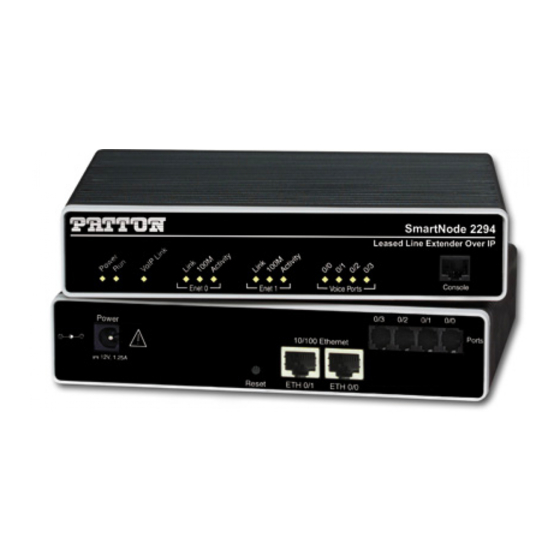
List of Figures SmartNode extender (SmartNode 2294 shown) ..........14 Examples of SmartNode 2292 and 2294 Series rear panels . -
Page 7: List Of Tables
List of Tables General conventions ..............12 Rear panel ports . -
Page 8: About This Guide
Chapter 5 on page 35 contains definitions for the LED status indicators • Chapter 6 on page 37 contains information on contacting Patton technical support for assistance • Appendix A on page 40 contains compliance and regulatory information for the extenders •... - Page 9 SmartNode 2290 Series User Manual About this guide Precautions Notes and cautions, which have the following meanings, are used throughout this guide to help you become aware of potential extender problems. Warnings relate to personal injury issues, and Cautions refer to potential property damage.
-
Page 10: Safety When Working With Electricity
Safety when working with electricity • This device contains no user serviceable parts. The equipment shall be returned to Patton Electronics for repairs, or repaired by qualified service personnel. • Mains Voltage: Do not open the case when the power cord is connected. For systems without a power switch, line voltages are present within the power supply when the power cord is connected. -
Page 11: Preventing Electrostatic Discharge Damage
SmartNode 2290 Series User Manual About this guide Preventing electrostatic discharge damage When starting to install interface cards place the interface card on its shielded plastic bag if you lay it on your bench. Electrostatic Discharge (ESD) can damage equipment and impair electrical circuitry. -
Page 12: General Conventions
SmartNode 2290 Series User Manual About this guide Typographical conventions used in this document This section describes the typographical conventions and terms used in this guide. General conventions The procedures described in this manual use the following text conventions: Table 1. General conventions... -
Page 13: General Information
Chapter 1 General information Chapter contents SmartNode Series Leased-Line Extenders overview....................14 SmartNode 2292 and 2294 Leased-Line Extenders ..................15 Ports descriptions ............................16 Reset button behavior ..........................16... -
Page 14: Smartnode Series Leased-Line Extenders Overview
SmartNode 2290 Series User Manual 1 • General information SmartNode Series Leased-Line Extenders overview The SmartNode 2292 and 2294 Series Leased-Line Extenders (see figure 1) combine IP routing, VPN/Secu- rity, and Quality of Service for up to 4 transparent voice channels and FAX calls over any IP or PSTN network. -
Page 15: Smartnode 2292 And 2294 Leased-Line Extenders
SmartNode 2290 Series User Manual 1 • General information SmartNode 2292 and 2294 Leased-Line Extenders The SmartNode 2292 and 2294 models are compact Leased-Line Extenderss over IP that support two or four VoIP channels, depending on the number of ports (see... -
Page 16: Rear Panel Ports
SmartNode 2290 Series User Manual 1 • General information External power supply connector (accepts 12 VDC, 1.25 A, from external AC adapter) Ports , 1.25A ETH 0/1 ETH 0/0 Reset .2 5 0 /1 0 /0 r ts Figure 3. - Page 17 SmartNode 2290 Series User Manual 1 • General information • To restart the unit in bootloader mode (to be used only by trained SmartNode technicians)—Start with the unit powered off. Press and hold the Reset button while applying power to the unit. Release the Reset button when the Power LED starts blinking so the unit will enter bootloader mode.
-
Page 18: Applications Overview
Chapter 2 Applications overview Chapter contents Typical application ..............................19 Leased-line extension ............................19... -
Page 19: Typical Application
SmartNode 2290 Series User Manual 2 • Applications overview Typical application Leased-line extension The SmartNode 2292 and 2294 Series Leased-Line Extenders allow you to save big on leased line costs. Using only one extender on each side, audio information on up to four leased-lines can be transported over a packet- based network. -
Page 20: Hardware Installation
Chapter 3 Hardware installation Chapter contents Planning the installation............................21 Installation checklist ............................22 Site log ................................23 Network information ............................23 Network Diagram .............................23 IP related information .............................23 Software tools ..............................23 Power source ..............................23 Location and mounting requirements ......................24 Installing the SmartNode extender ........................24 Mounting the SmartNode extender ........................24... -
Page 21: Planning The Installation
SmartNode 2290 Series User Manual 3 • Hardware installation Planning the installation Before you start the actual installation, it is strongly recommended that you gather all the information needed to install and setup the device. See table 3 for an example of what pre-installment checks you might need to carry out. -
Page 22: Installation Checklist
SmartNode 2290 Series User Manual 3 • Hardware installation Installation checklist The installation checklist (see table 3) lists the tasks for installing a SmartNode 2292 or 2294 Series extender. Make a copy of this checklist and mark the entries as you complete each task. For each SmartNode 2292 or 2294 Series extender, include a copy of the completed checklist in your site log. -
Page 23: Site Log
3 • Hardware installation Site log Patton recommends that you maintain a site log to record all actions relevant to the system, if you do not already keep such a log. Site log entries should include information such as listed in table Table 4. -
Page 24: Location And Mounting Requirements
SmartNode 2290 Series User Manual 3 • Hardware installation Location and mounting requirements The SmartNode extender is intended to be placed on a desktop or similar sturdy, flat surface that offers easy access to the cables. Allow sufficient space at the rear of the chassis for cable connections. Additionally, you should consider the need to access the unit for future upgrades and maintenance. -
Page 25: Rear View Showing Location Of Ethernet Connectors And Voice Ports (Smartnode 2294 Shown)
SmartNode 2290 Series User Manual 3 • Hardware installation Installing an interface cable on the extender’s voice ports The SmartNode extender comes with at least two voice ports (see figure 6) located on the back of the extender. The voice ports are connected to analog devices via cables (see... -
Page 26: Analog Connection
SmartNode 2290 Series User Manual 3 • Hardware installation . 2 5 PSTN 0 / 1 wall plate 0 / 0 r t s RJ-11, male RJ-11, male Figure 8. Analog connection r t s Socket Plug Figure 9. RJ-11 pinout diagram Table 5. -
Page 27: Connecting A Smartnode 2294 Series Device To A Hub
SmartNode 2290 Series User Manual 3 • Hardware installation Installing the Ethernet cable The SmartNode 2292 Series has automatic MDX (auto-cross-over) detection and configuration on the Ether- net ports. Any of the two ports can be connected to a host or hub/switch with a straight-through wired cable... -
Page 28: Connecting To A Host
SmartNode 2290 Series User Manual 3 • Hardware installation . 2 5 0 / 1 0 / 0 r t s Host Cross-over cable RJ-45, male RJ-45, 1 TX+ Twisted pair 1 2 TX- 3 RX+ Twisted pair 2 6 RX- Figure 11. -
Page 29: Power Connector Location On Rear Panel
SmartNode 2290 Series User Manual 3 • Hardware installation Connecting to external power source The extender comes with an external power supply. This section describes installing the power cord into the extender. Do the following: Note Do not connect the power cord to the power outlet at this time. -
Page 30: Smartnode Extender Front Panel Leds And Console Port Locations (Smartnode 2294 Shown)
SmartNode 2290 Series User Manual 3 • Hardware installation o le r t s SmartNode 2294 Leased-Line Extender Over IP Console Voice Power VoIP Link Port 0/3 Enet 0 Enet 1 Voice Voice Console 100M 100M Port 0/0 port Port 0/2... -
Page 31: Getting Started With The Smartnode
Chapter 4 Getting started with the SmartNode Chapter contents Introduction ................................32 Configure the IP address............................33 Power connection and default configuration ....................33 Connect with the serial interface ........................33 Login ................................34... -
Page 32: Introduction
This chapter leads you through the basic steps to set up a new SmartNode and to download a configuration. Patton SmartNodes can be used for a wide variety of IP-based network applications. To support and ease the configuration of the SmartNodes configuration, templates for the most important applications are available on the Patton server at www.patton.com/voip. -
Page 33: Configure The Ip Address
PC or workstation that supports the serial interface (e.g. HyperTerm). Serial Terminal o le r ts Note A Patton Model 16F-561 RJ45 to DB-9 adapter is included with each SmartNode Series device Figure 15. Connecting to the terminal Terminal emulation program settings: •... -
Page 34: Login
SmartNode 2290 Series User Manual 4 • Getting started with the SmartNode Login 1. Accessing your SmartNode via the local console port (or via a Telnet session) causes the login screen to dis- play. Type the factory default login: administrator and leave the password empty. Press the Enter key after the password prompt. -
Page 35: Leds Status And Monitoring
Chapter 5 LEDs status and monitoring Chapter contents Status LEDs................................36... -
Page 36: Status Leds
SmartNode 2290 Series User Manual 5 • LEDs status and monitoring Status LEDs This chapter describes SmartNode VoIP extender front panel LEDs. Figure 16 shows SmartNode 2292 and 2294 Series LEDs. LED definitions are listed in table 8 on page 36. -
Page 37: Contacting Patton For Assistance
Chapter 6 Contacting Patton for assistance Chapter contents Introduction ................................38 Contact information..............................38 Warranty Service and Returned Merchandise Authorizations (RMAs)..............38 Warranty coverage ............................38 Out-of-warranty service ..........................38 Returns for credit ............................38 Return for credit policy ..........................39 RMA numbers ..............................39 Shipping instructions ..........................39... -
Page 38: Introduction
If you have ordered the wrong equipment or you are dissatisfied in any way, please contact us to request an RMA number to accept your return. Patton is not responsible for equipment returned without a Return Authorization. -
Page 39: Rma Numbers
RMA#: xxxx 7622 Rickenbacker Dr. Gaithersburg, MD 20879-4773 USA Patton will ship the equipment back to you in the same manner you ship it to us. Patton will pay the return shipping costs. Warranty Service and Returned Merchandise Authorizations (RMAs) - Page 40 Appendix A Compliance information Chapter contents Compliance ................................41 ................................41 Safety ................................41 CE Declaration of Conformity ..........................41...
-
Page 41: A Compliance Information
The safety advice in the documentation accompanying this product shall be obeyed. The conformity to the above directive is indicated by CE sign on the device. The signed Declaration of Conformity can be downloaded at www.patton.com/certifications. Compliance... - Page 42 Appendix B Specifications Chapter contents Capacity ................................43 Audio connectivity ..............................43 Data Services .................................43 Quality of Service ..............................43 Voice Signaling..............................43 Voice Processing..............................44 Management .................................44 System...................................44 Temperature................................44 Humidity ................................44...
-
Page 43: B Specifications
SmartNode 2290 Series User Manual B • Specifications Capacity 2 audio lines (2292) 4 audio lines (2294) Audio connectivity 2-wire RJ-11 Bandwidth 4kHz, Impedance 600-ohm Narrow Band FXS style hybrid transmit/receive Data Services Two 10/100 Ethernet ports Complete IP access router DHCP Client &... -
Page 44: Voice Processing
SmartNode 2290 Series User Manual B • Specifications Voice Processing CODEC G.711 a-law/mu-law, G.723, G.729ab, G.726, G.727. T.38 fax relay (9.6 k, 14.4k) G.711 transparent fax and bypass Management Web/HTTP, CLI with local console and remote Telnet access TFTP configuration & firmware loading... - Page 45 Appendix C Cabling Chapter contents Introduction ................................46 Serial console.................................46 Ethernet 10Base-T and 100Base-T ........................47 Analog FXS ................................48...
-
Page 46: C Cabling
The SmartNode can be connected to a serial terminal over its serial console port, as depicted in figure Serial Terminal o le r ts A Patton Model 16F-561 RJ45 to DB-9 adapter is included with Note each SmartNode Series device Figure 17. Connecting a serial terminal Note See section “Console port”... -
Page 47: Ethernet 10Base-T And 100Base-T
SmartNode 2290 Series User Manual C • Cabling Ethernet 10Base-T and 100Base-T Ethernet devices (10Base-T/100Base-T) are connected to the SmartNode over a cable with RJ-45 plugs. Use a cross-over cable to a host, or a straight cable to a hub. See... -
Page 48: Analog Fxs
SmartNode 2290 Series User Manual C • Cabling . 2 5 0 / 1 0 / 0 r t s Straight-through cable RJ-45, male RJ-45, male 1 Rx+ 2 Rx- 3 Tx+ 6 Tx- Figure 19. Ethernet straight-through Analog FXS Applicable to SmartNodes equipped with FXS ports. - Page 49 Appendix D Port pin-outs Chapter contents Introduction ................................50 Console port................................50 Ethernet 10Base-T and 100Base-T port ........................50 Voice port ................................50...
-
Page 50: D Port Pin-Outs
SmartNode 2290 Series User Manual D • Port pin-outs Introduction This section provides pin-out information for the ports of the SmartNode. Console port Figure 21. EIA-561 (RJ-45 8-pin) port Note Pins not listed are not used. Ethernet 10Base-T and 100Base-T port Table 9. -
Page 51: Installation Checklist
Appendix E Installation checklist Chapter contents Introduction ................................52... -
Page 52: Introduction
SmartNode 2290 Series User Manual E • Installation checklist Introduction This appendix lists the tasks for installing a SmartNode 2292 or 2294 Series extender (see table 11) . Make a copy of this checklist and mark the entries as you complete each task. For each SmartNode 2292 or 2294 Series extender, include a copy of the completed checklist in your site log.
Need help?
Do you have a question about the SmartNode 2290 Series and is the answer not in the manual?
Questions and answers