Table of Contents
Advertisement
Quick Links
For Quick
Start Installation
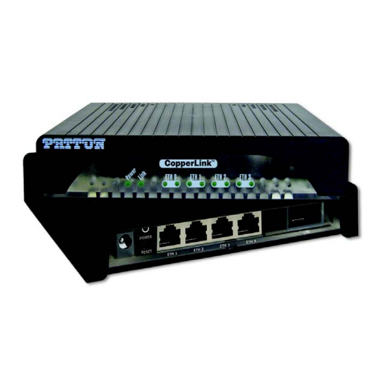
CopperLink Model 1314
Long Range Ethernet Extender
User Manual
Important
This is a Class A device and is intended for use in a light industrial environment. It is not intended nor approved for use in an industrial
or residential environment.
REGULATORY MODEL NUMBER: 03340D4-001
Sales Office:
+1 (301) 975-1000
Technical Support:
+1 (301) 975-1007
E-mail:
support@patton.com
WWW:
www.patton.com
Part Number: 07MCL1314, Rev. C
Revised: August 10, 2012
Advertisement
Table of Contents

Related Manuals for Patton 1314


Summary of Contents for Patton 1314
-
Page 1: Copperlink Model 1314
For Quick Start Installation CopperLink Model 1314 Long Range Ethernet Extender User Manual Important This is a Class A device and is intended for use in a light industrial environment. It is not intended nor approved for use in an industrial or residential environment. - Page 2 Patton Electronics Company, Inc. 7622 Rickenbacker Drive Gaithersburg, MD 20879 USA Tel: +1 (301) 975-1000 Fax: +1 (301) 869-9293 Support: +1 (301) 975-1007 Web: www.patton.com E-mail: support@patton.com Trademark Statement The term CopperLink is a trademark of Patton Electronics Company. All other trade- marks presented in this document are the property of their respective owners.
-
Page 3: Summary Table Of Contents
Summary Table of Contents General information ............................13 2 Configuration..............................16 CopperLink installation ..........................24 Operation ..............................27 Software Upgrade ............................29 Contacting Patton for assistance ........................31 Compliance information ..........................34 Specifications ..............................36 Factory replacement parts and accessories .................... -
Page 4: Table Of Contents
.......................11 General observations ............................12 Typographical conventions used in this document....................12 General conventions ............................12 General information ............................13 CopperLink Model 1314 overview ........................14 Features .................................14 Power input connector ............................15 External AC universal power supply ........................15 External 48 VDC power supply ........................15... - Page 5 CopperLink Model 1314 User Manual Table of Contents Power (Green) ............................28 Link (Green) .............................28 ETH Activity (Green) ..........................28 ETH Link (Green) ............................28 Software Upgrade ............................29 Introduction ................................30 Contacting Patton for assistance ........................31 Introduction ................................32 Contact information..............................32 Patton support headquarters in the USA ......................32...
- Page 6 CopperLink Model 1314 User Manual Table of Contents Third party software licenses..........................39 Factory replacement parts and accessories ....................40 Factory replacement parts and accessories ......................41 Interface pinouts ............................42 Line port ................................43 Ethernet port.................................43...
-
Page 7: List Of Figures
CopperLink Model 1314 ........ -
Page 8: List Of Tables
List of Tables General conventions ..............12 CopperLink configurable parameters . -
Page 9: About This Guide
About this guide This guide describes installing and operating the Patton Electronics CopperLink™ Model 1314 Long Range Ethernet Extender. Audience This guide is intended for the following users: • Operators • Installers • Maintenance technicians Structure This guide contains the following chapters and appendices: •... -
Page 10: Precautions
CopperLink Model 1314 User Manual Precautions Notes, cautions, and warnings, which have the following meanings, are used throughout this guide to help you become aware of potential problems. Warnings are intended to prevent safety hazards that could result in per- sonal injury. -
Page 11: Safety When Working With Electricity
CopperLink Model 1314 User Manual Safety when working with electricity • Do not open the device when the power cord is connected. For systems without a power switch and without an external power adapter, line volt- ages are present within the device when the power cord is connected. -
Page 12: General Observations
CopperLink Model 1314 User Manual Electrostatic Discharge (ESD) can damage equipment and impair electrical circuitry. It occurs when electronic printed circuit cards are improperly handled and can result in complete or intermittent CAUTION failures. Do the following to prevent ESD: Always follow ESD prevention procedures when removing and •... -
Page 13: General Information
Chapter 1 General information Chapter contents CopperLink Model 1314 overview ........................14 Features .................................14 Power input connector ............................15 External AC universal power supply ........................15 External 48 VDC power supply ........................15... -
Page 14: Copperlink Model 1314 Overview
CopperLink Model 1314 User Manual 1 • General information CopperLink Model 1314 overview The CL1314 CopperLink Ethernet Extenders are easy to use and take advantage of existing copper twisted-pair infra- structure to connect Ethernet networks or devices at high speeds over long distances. The CL1314 connects at speeds up to 5.7 Mbps with distances ranging from 3.4 to 5.4 km (2.0 to 3.4 miles) on standard 0.5 mm (24 AWG) voice-grade... -
Page 15: Power Input Connector
CopperLink Model 1314 User Manual 1 • General information Power input connector The CopperLink comes with an AC or DC power supply. (See section “Power and power supply specifica- tions” on page 38.) • The power connection to the CL1314 is a 2.5 mm barrel receptacle with the center conductor positive... -
Page 16: Configuration
Chapter 2 Configuration Chapter contents Introduction ................................17 Hardware (DIP-switch) configuration ......................17 Configuring the DIP switches .........................17 DIP switch settings ............................18 DIP switch settings: Data Rate ........................19 Ethernet Management Port ..........................22 CopperLink Status Command ........................22 Help Commands ............................22 Example Command Line Interface Session ....................23... -
Page 17: Introduction
CopperLink Model 1314 User Manual 2 • Configuration Introduction You can configure the CopperLink through the hardware configuration via DIP switches. Hardware (DIP-switch) configuration To use DIP-switch configuration you must first set the DIP switches to a position other than all OFF or all ON before powering-up the CopperLink. -
Page 18: Dip Switch Settings
CopperLink Model 1314 User Manual 2 • Configuration 1 2 3 4 5 6 7 8 1 2 3 4 5 6 7 8 1 2 3 4 5 6 7 8 Model CL1314 Figure 3. Underside of CL1314 showing location of DIP switches The three sets of DIP switches on the underside of the CL1314 are referred to as S1, S3 and S4. -
Page 19: Dip Switch Settings: Data Rate
CopperLink Model 1314 User Manual 2 • Configuration DIP switch settings: Data Rate Switches S4-2 through S4-8 define the CopperLink line rate. Table 3. S4-2 through S4-8 Data Rate DIP switch settings S4-2 S4-3 S4-4 S4-5 S4-6 S4-7 S4-8 Data Rate (kbps) - Page 20 CopperLink Model 1314 User Manual 2 • Configuration Table 3. S4-2 through S4-8 Data Rate DIP switch settings (Continued) S4-2 S4-3 S4-4 S4-5 S4-6 S4-7 S4-8 Data Rate (kbps) 2496 2560 2624 2688 2752 2816 2880 2944 3008 3072 3136...
- Page 21 CopperLink Model 1314 User Manual 2 • Configuration Table 3. S4-2 through S4-8 Data Rate DIP switch settings (Continued) S4-2 S4-3 S4-4 S4-5 S4-6 S4-7 S4-8 Data Rate (kbps) 4928 4992 5056 5120 5184 5248 5312 5376 5440 5504 5568...
-
Page 22: Ethernet Management Port
CopperLink Model 1314 User Manual 2 • Configuration Ethernet Management Port The CL1314 offers a 10/100 Ethernet port to view the current DIP switch settings via Telnet sessions. The Ethernet interface default IP address is 192.168.200.1. Log into the CL1314 management port using the pass- word superuser. -
Page 23: Example Command Line Interface Session
CopperLink Model 1314 User Manual 2 • Configuration Example Command Line Interface Session CL1314 Command Shell Password: CL1314> status configuration: copperlink mode: local copperlink rate: 5696 line probe: disabled status: actual rate: loss of signal: unavailable noise margin: snr: sync state:... -
Page 24: Copperlink Installation
Chapter 3 CopperLink installation Chapter contents Installation ................................25 Connecting the CopperLink interface ......................25 Connecting the Ethernet interface ........................26 Connecting power ............................26 External AC universal power supply ......................26 DC Power ..............................26... -
Page 25: Installation
CopperLink Model 1314 User Manual 3 • CopperLink installation Installation Once the CL1314 is properly configured, it is ready to connect to the CopperLink interface and to the power source. This section explains how to make these connections. Model CL1314... -
Page 26: Connecting The Ethernet Interface
CopperLink Model 1314 User Manual 3 • CopperLink installation Connecting the Ethernet interface This section describes how to connect the Ethernet ports to your network equipment. The interconnecting cables shall be acceptable for external use and shall be rated for the proper application with respect to volt-... -
Page 27: Operation
Chapter 4 Operation Chapter contents Introduction ................................28 Power-up ................................28 LED status monitors ............................28 Power (Green) ............................28 Link (Green) .............................28 ETH Activity (Green) ..........................28 ETH Link (Green) ............................28... -
Page 28: Introduction
CopperLink Model 1314 User Manual 4 • Operation Introduction Once the CL1314 is properly configured and installed, it should operate transparently. The following sections describe power-up, reading the LED status monitors, and using the built-in loopback test modes. Power-up To apply power to the CL1314, first be sure that you have read section “Power input connector”... -
Page 29: Software Upgrade
Chapter 5 Software Upgrade Chapter contents Introduction ................................30... -
Page 30: Introduction
CopperLink Model 1314 User Manual 5 • Software Upgrade Introduction The software upgrade feature is available through BOOTP/TFTP. The software upgrade takes approximately 2-3 minutes to complete. To upgrade the software: 1. Connect to the CL1314 via the Ethernet management port and a Telnet session. -
Page 31: Contacting Patton For Assistance
Chapter 6 Contacting Patton for assistance Chapter contents Introduction ................................32 Contact information..............................32 Patton support headquarters in the USA ......................32 Alternate Patton support for Europe, Middle East, and Africa (EMEA) ............32 Warranty Service and Returned Merchandise Authorizations (RMAs)..............32 Warranty coverage ............................32 Out-of-warranty service ..........................33 Returns for credit... -
Page 32: Introduction
CopperLink Model 1314 User Manual 6 • Contacting Patton for assistance Introduction This chapter contains the following information: • “Contact information”—describes how to contact Patton technical support for assistance. • “Warranty Service and Returned Merchandise Authorizations (RMAs)”—contains information about the warranty and obtaining a return merchandise authorization (RMA). -
Page 33: Out-Of-Warranty Service
CopperLink Model 1314 User Manual 6 • Contacting Patton for assistance Out-of-warranty service Patton services what we sell, no matter how you acquired it, including malfunctioning products that are no longer under warranty. Our products have a flat fee for repairs. Units damaged by lightning or other catastro- phes may require replacement. -
Page 34: A Compliance Information
Appendix A Compliance information Chapter contents Compliance ................................35 ................................35 Safety ................................35 Radio and TV Interference (FCC Part 15) ......................35 CE Declaration of Conformity ..........................35 Authorized European Representative ........................35... -
Page 35: Compliance
CopperLink Model 1314 User Manual A • Compliance information Compliance • FCC Part 15, Class A • EN55022, Class A • EN55024 Safety • UL 60950-1/CSA C22.2 N0. 60950-1 • IEC/EN60950-1 2nd edition • AS/NZS 60950-1 Radio and TV Interference (FCC Part 15) This device generates and uses radio frequency energy, and if not installed and used properly-that is, in strict accordance with the manufacturer’s instructions-may cause interference to radio and television reception. - Page 36 Appendix B Specifications Chapter contents Line rate ................................37 Ethernet interface ..............................37 Status LEDs................................37 Power (Green) ............................37 Link (Green) .............................37 ETH Activity (Green) ..........................37 ETH Link (Green) ............................37 Configuration................................37 Power and power supply specifications ........................38 External AC universal power supply ........................38 External 48 VDC power supply ........................38 Transmission line...
-
Page 37: B Specifications
CopperLink Model 1314 User Manual B • Specifications Line rate 192 to 5696 kbps (64k increments) Ethernet interface Four RJ-45, 10/100Base-T, IEEE 802.3 Ethernet Status LEDs Power (Green) The Power LED glows solid during normal operation. At startup, during the POST, the LED blinks once every second. -
Page 38: Power And Power Supply Specifications
CopperLink Model 1314 User Manual B • Specifications Power and power supply specifications The CL1314 comes with either an AC or DC power supply: • The supply’s connection to the CL1314 is a 2.5 mm barrel receptacle with the center conductor positive. -
Page 39: Transmission Line
CopperLink Model 1314 User Manual B • Specifications Transmission line Single Twisted Pair Line coding TC-PAM (Trellis Coded Pulse Amplitude Modulation) Line interface Transformer coupled, 2500 VRMS isolation CopperLink physical connection RJ-45, 2-wire polarity insensitive pins 4 and 5 Environment Operating temp: 32–122°F (0–50°C) -
Page 40: Factory Replacement Parts And Accessories
Appendix C Factory replacement parts and accessories Chapter contents Factory replacement parts and accessories ......................41... -
Page 41: Factory Replacement Parts And Accessories
CopperLink Model 1314 User Manual C • Factory replacement parts and accessories Factory replacement parts and accessories Power Supplies PS-03671H1-00 100-240VAC (12V, DC/2A) Wall mount power adapter Power Adapters 12-130 European replacement plug 12-129 American replacement plug 12-131 United Kingdom plug... -
Page 42: Interface Pinouts
Appendix D Interface pinouts Chapter contents Line port ................................43 Ethernet port.................................43... -
Page 43: Line Port
CopperLink Model 1314 User Manual D • Interface pinouts Line port RJ-45 connector Pin # Signal No connection No connection No connection Ring No connection No connection No connection Ethernet port Table 4. RJ45 socket 10/100Base-T Signal Note Pins not listed are not used.
Need help?
Do you have a question about the 1314 and is the answer not in the manual?
Questions and answers