Table of Contents
Advertisement
Quick Links
Advertisement
Table of Contents

Related Manuals for Patton CopperLINK 2113A


Summary of Contents for Patton CopperLINK 2113A
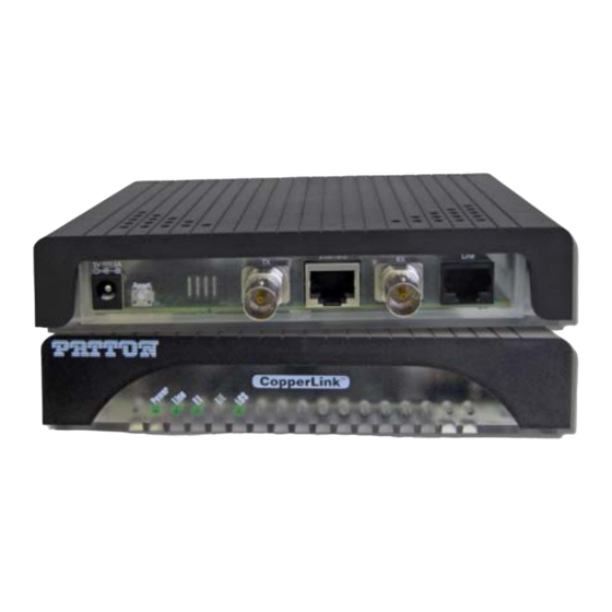
- Page 1 USER MANUAL MODEL 2113A CopperLINK™ E1 Extender REGULATORY MODEL NUMBER: 03340D4-001 This is a Class A device and is not intended for use in a residential environment. SALES OFFICE Part# 07M2113A-UM Rev. A (301) 975-1000 Revised 2/2/12 TECHNICAL SUPPORT (301) 975-1007...
-
Page 2: Table Of Contents
A.6 Transmission Line ............... 13 A.7 Line Coding ................13 A.8 Line Interface ................13 A.9 Line Physical Connection ............13 A.10 Power Supply ................13 A.11 Environmental ................13 A.12 Dimensions ................. 13 Model 2113A Series Factory Replacement Parts and Accessories........14... -
Page 3: Warranty Information
Under no condition shall Patton Electronics be liable for any damages incurred by the use of this product. These damages include, but are not limited to, the following: lost profits, lost savings and incidental or consequential damages arising from the use of or inability to use this product. -
Page 4: Radio And Tv Interference (Fcc Part 15)
AC outlet (such that the computing equipment and receiver are on different branches). 1.3 CE DECLARATION OF CONFORMITY Patton Electronics, Inc declares that this device is in compliance with the essential requirements and other relevant provisions of Directive 2004/108/EC relating to electromagnetic compatibility and Directive 2006/95/EC relating to electrical equipment designed for use within cer- tain voltage limits. -
Page 5: Safety When Working With Electricity
1.6 SAFETY WHEN WORKING WITH ELECTRICITY • This device contains no user serviceable parts. This device can only be repaired by qualified service per- sonnel. • Do not open the device when the power cord is con- nected. For systems without a power switch and without an external power adapter, line voltages are present within the device when the power cord is connected. - Page 6 In accordance with the requirements of council direc- tive 2002/96/EC on Waste of Electrical and Electronic Equipment (WEEE), ensure that at end-of-life you sepa- rate this product from other waste and scrap and deliver to the WEEE collection system in your country for recy- cling.
-
Page 7: General Information
E1 extension connectivity to ISPs, PTTs, and enterprise environments using binder group friendly TC-PAM modulation. Line connection is made with an RJ-45 jack. The Model 2113A is powered by an 100/230 VAC (Universal) supply. The E1 Extender features exter- nally-accessible DIP switches, loopback diagnostics, and CopperLink Plug ‘n’... -
Page 8: Installation
CAUTION perature, flammability, and mechanical serviceability. To install the 2113A E1 Extender, do the following: 1. Connect the line interface (refer to section 3.1, “Connecting the Line Port” on page 9) 2. Connect the E1 interface (refer to section 3.2, “Connecting the E1 Interface”... -
Page 9: Connecting The Line Port
Follow the steps below to connect the Model 2113A CopperLINK Line port. Note The Model 2113A units work in pairs. One of the units must be configured as a (L) Local unit, and the other unit must be config- ured as a (R) Remote unit. -
Page 10: Connecting The E1 Interface
An external AC or DC power supply is available separately. This connec- tion is made via the barrel jack on the rear panel of the Model 2113A. No configuration is necessary for the power supply (See Appendix B for domestic and international power supply and cord options). -
Page 11: Operation
“Connecting Power” on page 10 to verify that the unit is connected to the appropriate power source. 4.1 FRONT PANEL LED STATUS MONITORS The Model 2113A features five front panel LEDs that monitor power, the line connection, the E1 connection, and any signal errors. Loss of Signal... -
Page 12: Configuration And Dip Switches
4.2 CONFIGURATION AND DIP SWITCHES The CopperLink 2113A E1 Extender is Plug ‘n’ Play enabled and does not require any configuration by the user. Note The user should NOT change any of the dip switches except for S4-1 (if necessary). If the user changes the position of any of the dip switches (except for S4-1), it will affect the operation of the unit. -
Page 13: Specifications
APPENDIX A SPECIFICATIONS A.1 CIRCUIT RATE • Model 2113A - 2.048 Mbps A.2 CIRCUIT INTERFACE • G.703/G.704 interface. Either 75 Ohms (unbalanced) or 120 Ohms (bal- anced). Pins 1 & 2 are Receive. Pins 4 & 5 are transmit. A.3 CIRCUIT DEFAULTS •... -
Page 14: Model 2113A Series Factory Replacement Parts And Accessories
APPENDIX B MODEL 2113A SERIES FACTORY REPLACEMENT PARTS AND ACCESSORIES Patton Model # Description Base Models 2113A/EUI-2PK High Speed CopperLink E1 Extender Kit (Local and Remote); RJ45 Line, 100-240VAC 07M2113A-UM User Manual Power Supplies PS-03671H1-002 100-240VAC (12V, DC/2A) Wall mount power adapter... - Page 15 _________________________________________________________ _________________________________________________________ _________________________________________________________ _________________________________________________________ _________________________________________________________ _________________________________________________________ _________________________________________________________ _________________________________________________________ _________________________________________________________ _________________________________________________________ _________________________________________________________ _________________________________________________________ _________________________________________________________ _________________________________________________________ _________________________________________________________ _________________________________________________________...
- Page 16 Copyright © 2012. Patton Electronics Company All Rights Reserved.
Need help?
Do you have a question about the CopperLINK 2113A and is the answer not in the manual?
Questions and answers