Table of Contents
Advertisement
Quick Links
CopperLink™ Model 1101E
Industrial Grade Line Power PoE
Ethernet Extender
User Manual
This is a Class B device and is approved for use in a residential environment.
Sales Office:
+1 (301) 975-1000
Technical Support:
+1 (301) 975-1007
E-mail:
support@patton.com
WWW:
www.patton.com
Part Number: 07MCL1101E-UM, Rev. B
Revised: June 3, 2020
Advertisement
Table of Contents

Related Manuals for Patton CopperLink 1101E


Summary of Contents for Patton CopperLink 1101E
- Page 1 User Manual This is a Class B device and is approved for use in a residential environment. Sales Office: +1 (301) 975-1000 Technical Support: +1 (301) 975-1007 E-mail: support@patton.com WWW: www.patton.com Part Number: 07MCL1101E-UM, Rev. B Revised: June 3, 2020...
- Page 2 Under no condition shall Patton Electronics be liable for any damages incurred by the use of this product. These damages include, but are not limited to, the following: lost profits, lost savings and incidental or consequential damages arising from the use of or inability to use this product.
-
Page 3: Summary Table Of Contents
3 Operation................................32 Contacting Patton for assistance. -
Page 4: Table Of Contents
........................33 Contacting Patton for assistance.........................34 Introduction ................................35... - Page 5 CopperLink Line Power 1101E PoE Extender User Manual Warranty Service and Returned Merchandise Authorizations (RMAs)..............35 Warranty Coverage ............................35 Out-of-Warranty Service ..........................35 Returns for Credit ............................35 RMA Numbers ...............................36 Shipping Instructions ............................36 ...........................37 Compliance Information Regulatory Information ............................38...
-
Page 6: List Of Figures
List of Figures Typical application ..............12 Data path . -
Page 7: List Of Tables
List of Tables RJ-45 wire modes ............... 28 Terminal block wire modes . -
Page 8: About This Guide
CL1101E power and data performance values for RG59 coaxial and twisted-pair cables For best results, read the contents of this guide before you install the CopperLink 1101E. Precautions Notes and cautions, which have the following meanings, are used throughout this guide to help you become aware of potential Router modem problems. -
Page 9: Safety When Working With Electricity
CopperLink Line Power 1101E PoE Extender User Manual About This Guide The alert symbol and CAUTION heading indicate a potential hazard. Strictly follow the instructions to avoid property damage. CAUTION The shock hazard symbol and CAUTION heading indicate a potential electric shock hazard. Strictly follow the instructions to avoid property damage caused by electric shock. - Page 10 CopperLink Line Power 1101E PoE Extender User Manual About This Guide In accordance with the requirements of council directive 2002/ 96/EC on Waste of Electrical and Electronic Equipment (WEEE), ensure that at end-of-life you separate this product from other waste and scrap and deliver to the WEEE collection system in your country for recycling.
-
Page 11: General Information
Chapter 1 General information Chapter contents Overview ................................12 Features .................................12 Description................................12 Unit Definitions ..............................13 Data ..................................13 Power ..................................13 Power-across-link application ........................13 Remote-power application ........................14 Front panel description............................15 Power Transmission ..............................16 General Background ............................16 Wire Specifics ..............................17 CL1101E specifics ............................18... -
Page 12: Overview
1 • General information Overview Thank you for purchasing this Patton Electronics product. This product has been thoroughly inspected and tested and is warranted for one year for parts and labor. If any questions or problems arise during installation or use of this product, contact Patton Electronics Technical Support at +(301) 975-1007. -
Page 13: Unit Definitions
CopperLink Line Power 1101E PoE Extender User Manual 1 • General information Unit Definitions Local Customer Endpoint (LCE)—Customer equipment that is typically closer to the centralized location. This is often times a server or a network switch. Remote Customer Endpoint (RCE)—Customer equipment that is typically far away from other devices. It is often a phone, camera, or other small device. -
Page 14: Power Supply And Data Paths For Power-Across-Link Application
CopperLink Line Power 1101E PoE Extender User Manual 1 • General information If the RCE’s input power is grounded in any way, it will short out the power being sent which could cause equip- ment damage or personal injury. WARNING The Remote Ethernet Extender receives power. -
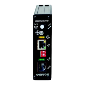
Page 15: Front Panel Description
CopperLink Line Power 1101E PoE Extender User Manual 1 • General information Figure 5. CL1101E front panels Front panel description The following describes the ports, indicators, and grounding stud for the CL1101E (see figure • Grounding stud—Prevents high voltage surges from reaching human accessible components (the shielded connector). -
Page 16: Power Transmission
CopperLink Line Power 1101E PoE Extender User Manual 1 • General information Power supply can be installed on remote unit even if the unit is receiving Note power across the line. Used for data extension only mode. The power supply provided is 12 VDC center positive. ∕... -
Page 17: Wire Specifics
This effec- tively means seeing a 27 V drop across the wire (when using the Patton PoE power supply) when it is sending the maximum amount of power. -
Page 18: Cl1101E Specifics
CopperLink Line Power 1101E PoE Extender User Manual 1 • General information Or more concretely for 24 AWG solid copper, (0.7 x 27 x 27)/(2 x 0.09 x 10) = 284 meters If you had more wire pairs, then further distances are possible, just multiply by the number of wire pairs. CL1101E specifics The above example is completely hypothetical but is realistic. -
Page 19: Installation
Chapter 2 Installation Chapter contents Planning the Installation............................20 Installing accessories ..............................20 Installing the DIN Rail Installation Kit; 35MM (INS/A-DIN-35) ..............20 Installing the 19" Rackmount Adjustable Depth 35MM DIN Rail Kit (NS-1001R-19ADJDIN) ....23 Installing the Mounting Ears Installation Kit (INS-KIT-MNTEARS) ............24 Installing the Mounting Plate Installation Kit (INS-KIT-MNTPLATE) ............26 Connecting the Line Interface... -
Page 20: Planning The Installation
CopperLink Line Power 1101E PoE Extender User Manual 2 • Installation Planning the Installation The Interconnecting cables shall be acceptable for external use and shall be rated for the proper application with respect to volt- age, current, anticipated temperature, flammability, and CAUTION mechanical serviceability. -
Page 21: Removing The Rear Panel
CopperLink Line Power 1101E PoE Extender User Manual 2 • Installation Figure 7. Removing the rear panel 2. Install the 35mm DIN clip onto the rear panel using the self-tapping screws (included in the installation kit package) as shown in figure Figure 8. -
Page 22: Din Rail Types
CopperLink Line Power 1101E PoE Extender User Manual 2 • Installation Figure 9. Installing the rear panel. 4. The mounting clip can be attached to the following types of DIN rail (see figure 10): – Top hat section types NS 35/7.5 (35 H × 7.5 D mm) and NS 35/15 (35 H × 15 D mm) –... -
Page 23: Installing The 19" Rackmount Adjustable Depth 35Mm Din Rail Kit (Ns-1001R-19Adjdin)
CopperLink Line Power 1101E PoE Extender User Manual 2 • Installation Install the CL1101E to the DIN rail by attaching the appropriate slot on the 35mm clip to the lower DIN rail lip (see callout 1 on figure 11). Figure 11. Installing the CL1101E onto the DIN rail 5. -
Page 24: Installing The Mounting Ears Installation Kit (Ins-Kit-Mntears)
CopperLink Line Power 1101E PoE Extender User Manual 2 • Installation Figure 12. Installing the Rackmount DIN rail onto the rack 2. Refer to section “Installing the DIN Rail Installation Kit; 35MM (INS/A-DIN-35)” on page 20, and per- form steps 1 through 5 to install the CL1101E onto the rail. The CL1101E has been installed on the rack;... -
Page 25: Installing The Mounting Ears
CopperLink Line Power 1101E PoE Extender User Manual 2 • Installation Figure 13. Installing the mounting ears 2. Slide a mounting ear into the top slot closest to the CL1101E back panel as shown in figure 3. Slide the remaining mounting ear into the bottom slot closest to the CL1101E back panel (see figure 13). -
Page 26: Installing The Mounting Plate Installation Kit (Ins-Kit-Mntplate)
CopperLink Line Power 1101E PoE Extender User Manual 2 • Installation The mounting ears have been installed on the CL1101E; proceed to section “Connecting the Line Interface” on page 26. Installing the Mounting Plate Installation Kit (INS-KIT-MNTPLATE) Do the following to install the mounting plate installation kit: 1. -
Page 27: Connecting The Rj-45 Line Interface
CopperLink Line Power 1101E PoE Extender User Manual 2 • Installation BNC (Coaxial) (see section “Connecting the BNC (Coaxial) Line Interface” on page 28) • The CL1101E units work in pairs. The CL1101E/L connects to the Note CL1101E/R. Actual distance and link performance may vary depending on the environ- Note ment and type/gauge of wire used. -
Page 28: Connecting The Terminal Block Line Interface
CopperLink Line Power 1101E PoE Extender User Manual 2 • Installation 3. The RJ-45 connector on the CL1101E’s twisted pair interface is polarity insensitive, and is wired for two, four, six or eight wires—pin-out to TIA/EIA T568A/B (see table Table 1. RJ-45 wire modes Pair Voltage –... -
Page 29: Connecting The 10/100Base-T Ethernet Interface
CopperLink Line Power 1101E PoE Extender User Manual 2 • Installation Connecting the 10/100Base-T Ethernet Interface Do the following to connect the 10/100Base-T Ethernet interface: 1. The RJ-45 Ethernet port is an Auto-MDIX 10/100Base-T that connects to a 10/100Base-T device or net- work. -
Page 30: Connecting The Grounding Stud
3. Connect the other end of the ground wire to an electrical ground nearest the CL1101E. Often this will be on an electrical panel or sub panel. If you cannot locate a nearby electrical ground, contact Patton Techni- cal Support at (301) 975-1000 to discuss an alternative grounding solution. -
Page 31: Configuring The Dip Switch
CopperLink Line Power 1101E PoE Extender User Manual 2 • Installation Configuring the DIP Switch DIP switch (see figure 18) settings are described in table Figure 18. 4-position DIP switch Table 5. DIP switch settings Switch (left to right) Function Down: 100 Mb, Down Down: 2-wire mode Remote only**... -
Page 32: Operation
Chapter 3 Operation Chapter contents Introduction ................................33 Front Panel LED Status Indicators ........................33... -
Page 33: Introduction
CopperLink Line Power 1101E PoE Extender User Manual 3 • Operation Introduction Once the CL1101Es are properly installed, they should operate transparently. No user settings required. This section describes reading the LED status monitors. Front Panel LED Status Indicators The CL1101E provides the following status indicators: •... -
Page 34: Contacting Patton For
Chapter 4 Contacting Patton for assistance Chapter contents Introduction ................................35 Contact information..............................35 Warranty Service and Returned Merchandise Authorizations (RMAs)..............35 Warranty Coverage ............................35 Out-of-Warranty Service ..........................35 Returns for Credit ............................35 Return-for-Credit Policy ...........................36 RMA Numbers ...............................36 Shipping Instructions ............................36... -
Page 35: Introduction
If you have ordered the wrong equipment or you are dissatisfied in any way, please contact us to request an RMA number to accept your return. Patton is not responsible for equipment returned without a Return Authorization. -
Page 36: Rma Numbers
RMA#: xxxx 7622 Rickenbacker Dr. Gaithersburg, MD 20879-4773 USA Patton will ship the equipment back to you in the same manner you ship it to us. Patton will pay the return shipping costs. Warranty Service and Returned Merchandise Authorizations (RMAs) -
Page 37: A Compliance Information
Appendix A Compliance Information Chapter contents Regulatory Information ............................38 EMC Directive: ..............................38 Low-Voltage Directive (Safety): ........................38 PSTN: ................................38 Radio and TV Interference (FCC Part 15) ......................38 CE Declaration of Conformity ..........................38 Authorized European Representative ........................38 Service ...................................39... -
Page 38: Regulatory Information
RoHS compliance and Council Directive 2009/125/EC establishing a frame- work for the setting of ecodesign requirements for energy-related products. The Declaration of Conformity may be obtained from Patton Electronics, Inc at www.patton.com/certifications. The safety advice in the documentation accompanying this device shall be obeyed. The conformity to the above directive is indicated by CE mark on the device. -
Page 39: Authorized European Representative
Oxford, OX1 1BE, UK Service All warranty and non-warranty repairs must be returned freight prepaid and insured to Patton Electronics. All returns must have a Return Materials Authorization number on the outside of the shipping container. This number may be obtained from Patton Electronics Technical Services at: •... -
Page 40: Specifications
Appendix B Specifications Chapter contents Line Connector ..............................41 LAN Connectors ..............................41 Transmission Line ..............................41 LED Status Indicators ............................41 Power Supply ................................41 External AC option: ............................41 Physical .................................41 Operating Temperature Range ........................41 Humidity ................................41 Dimensions ..............................41 Weight ................................41... -
Page 41: Line Connector
CopperLink Line Power 1101E PoE Extender User Manual B • Specifications Line Connector • RJ-45, Terminal Block, or BNC Coaxial LAN Connectors • 1 RJ-45, 10/100Base-T, IEEE 802.3 Ethernet (Local) IEEE 802.3af/at PoE Ethernet (Remote) • Transmission Line 1 to 4 pairs of 2-wire or coaxial (CL1101E/BNC) LED Status Indicators PoE LVL (4 yellow LEDs) •... -
Page 42: C Factory Replacement Parts And Accessories
Appendix C Factory Replacement Parts and Accessories Chapter contents CL1101E Factory Replacement Parts and Accessories ...................43... -
Page 43: Cl1101E Factory Replacement Parts And Accessories
CopperLink Line Power 1101E PoE Extender User Manual C • Factory Replacement Parts and Accessories CL1101E Factory Replacement Parts and Accessories Patton Model # Description Base Models C1101E/L/P/RJ45/EUI Industrial CopperLink Power Plus 10/100 Local Power Extender; 1x 10/ 100; RJ45 Line; 100–240VAC C1101E/R/PAFA/RJ45/E Industrial CopperLink Power Plus 10/100 Remote Extender w/PoE;... -
Page 44: D Interface Pin Assignment
Appendix D Interface Pin Assignment Chapter contents 10/100Base-T Interface ............................45 Ethernet (RJ-45) .............................45 Line Interface ................................46 RJ-45 ................................46 Terminal Block ...............................46 BNC (Coaxial) ..............................47... -
Page 45: 10/100Base-T Interface
CopperLink Line Power 1101E PoE Extender User Manual D • Interface Pin Assignment 10/100Base-T Interface Ethernet (RJ-45) Figure 19. CL1101E 10/100Base-T RJ-45 Connector Pin-out Table 8. RJ-45 wire modes Voltage Function Mode A + Tx + Mode A + Tx – Mode A –... -
Page 46: Line Interface
CopperLink Line Power 1101E PoE Extender User Manual D • Interface Pin Assignment Line Interface RJ-45 Figure 20. RJ-45 pin-out Table 9. RJ-45 wire modes Pair Voltage – – – – These devices are polarity sensitive. Note Note 2-wire mode—non-standard pin-out •... -
Page 47: Bnc (Coaxial)
CopperLink Line Power 1101E PoE Extender User Manual D • Interface Pin Assignment BNC (Coaxial) Table 11. Coaxial (BNC) wire modes Pair Voltage Inner Outer – Line Interface... -
Page 48: E Line Rate & Reach Chart
Appendix E Line Rate & Reach Chart Chapter contents CL1101E Power & Data Performance (Twisted Pair) ...................49 CL1101E Power Performance (Twisted Pair) ......................49 CL1101E Power & Data Performance (RG59) .....................50 CL1101E Power Performance (RG59) ........................50... -
Page 49: Cl1101E Power & Data Performance (Twisted Pair)
CopperLink Line Power 1101E PoE Extender User Manual E • Line Rate & Reach Chart CL1101E Power & Data Performance (Twisted Pair) Table 12. CL1101E power & data performance over twisted-pair wires 10 Mbps 100 Mbps 2 wire 4 wire 2 wire 4 wire 8 wire... -
Page 50: Cl1101E Power & Data Performance (Rg59)
CopperLink Line Power 1101E PoE Extender User Manual E • Line Rate & Reach Chart CL1101E Power & Data Performance (RG59) Table 14. CL1101E power & data performance over RG59 coaxial cable 10 Mbps 100 Mbps Min. distance feet (meters) (1.83) (1.83) Max.
Need help?
Do you have a question about the CopperLink 1101E and is the answer not in the manual?
Questions and answers