
Related Manuals for Patton 2168


Summary of Contents for Patton 2168
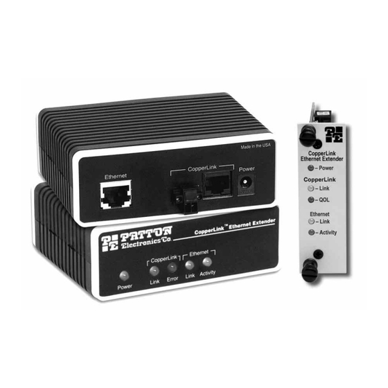
- Page 1 USER MANUAL MODEL 2168 CopperLink Ethernet Extender Part# 07M2168-A SALES OFFICE Doc# 058112UA (301) 975-1000 Revised 6/11/02 TECHNICAL SUPPORT (301) 975-1007 An ISO-9001Certified Company...
-
Page 2: Table Of Contents
A.7 Power Supply ................20 A.8 Temperature Range ..............20 A.9 Humidity ..................20 A.10 Dimensions ................. 20 Model 2168 Series Factory Replacement Parts and Accessories........21 Model 2168 Series Interface Pin Assignment ......22 C.1 10/100Base-T Interface .............. 22 RJ-45 ..................22... - Page 3 C.2 CopperLink Interface ..............22 RJ-45 ..................22 Terminal Block................22 Distance Chart, Based on 24 AWG (0.5 mm)......23...
-
Page 4: Warranty Information
The Model 2168 has been tested and found to comply with the limits for a Class A computing device in accordance with specifications in Sub- part B of Part 15 of FCC rules, which are designed to provide reasonable protection from such interference in a commercial installation. -
Page 5: Service
1.3 SERVICE All warranty and non-warranty repairs must be returned freight prepaid and insured to Patton Electronics. All returns must have a Return Materi- als Authorization number on the outside of the shipping container. This number may be obtained from Patton Electronics Technical Services at: •... -
Page 6: General Information
Ethernet LANs, remote PC’s, or any other network enabled 10/ 100Base-T device. Operating in pairs, a Model 2168/L (local) located at one end of the LAN extension and a Model 2168/R (remote) at the other end, these units can automatically forward LAN broadcasts, multicasts, and frames across a 2- wire voice-grade twisted-pair link. - Page 7 MAC addresses, only passing packets across the CopperLink that are meant for the remote peered LAN. Figure 1. Ethernet Extender allows copper instead of fiber for vertical Ethernet spans Multi-rate Ethernet Extenders are ideal for bridging Ethernet spans inside buildings that are beyond the 328-foot (100-meter) distance limit of Ethernet. As shown in Figure 1, connecting workgroups located on different floors in a building no longer requires expensive switches or the installation of low capacitance cable.
-
Page 8: Installation
Figure 2. Model 2168 standalone rear panel 3.2 RACK CARD INSTALLATION The Model 2168 rack card version comprises a front card and a rear card. Do the following to install the cards into the rack chassis: 1. Slide the rear card into the back of the chassis along the metal rails. - Page 9 4. Secure the front card using the captive fasteners. Note The Model 1001R14 chassis supports “hot swapping” of cards, so it is not necessary to power down the rack when you install or remove a Model 2168 rack card. CopperLink RJ-45 interface CopperLink...
-
Page 10: Connecting The Twisted-Pair Line Interface
Note The Model 2168 units work in pairs. One of the units must be a Model 2168/L (Local), and the other unit must be a Model 2168/ R (Remote). It does not matter which end is the 2168/L and which is the 2168/R. -
Page 11: Connecting The 10/100Base-T Ethernet Interface
RING Figure 5. Model 2168 (Terminal Block) twisted pair line interface. 3.4 CONNECTING THE 10/100BASE-T ETHERNET INTERFACE The shielded RJ-45 port labeled Ethernet is the 10/100Base-T interface. This port is designed to connect directly to a 10/100Base-T network. -
Page 12: Connecting The 10/100Base-T Ethernet Port To A Hub
3.5 CONNECTING POWER An external AC or DC power supply is available separately. This connec- tion is made via the barrel jack on the rear panel of the Model 2168. No configuration is necessary for the power supply (See Appendix B for domestic and international power supply and cord options). - Page 13 The Model 2168 does not have a power switch, so it powers up as soon as it is plugged in.
-
Page 14: Configuration
4.0 CONFIGURATION The Model 2168 has four DIP switches for configuring the unit for a wide variety of applications. This section describes switch locations and explains the different configurations. 4.1 CONFIGURING THE HARDWARE DIP SWITCHES Using a small flat-tip screwdriver, remove the protective cover located on the underside of the Model 2168 (see Figure 9). - Page 15 Switch toggle Push toggle up for ON position Push toggle down for 1 2 3 4 OFF position Figure 10. DIP switch orientation L i n t e n L i n L i n L i n Switch toggle t i v i t y Push toggle to left...
-
Page 16: Configuring Dip Switch S1
4.2 CONFIGURING DIP SWITCH S1 DIP switch S1 is where you configure the CopperLink line rate, symmet- ric or asymmetric, Ethernet full auto sense capability (100BaseT full or half duplex, 10BaseT full or half duplex) or limited auto sense (only 100BaseT half duplex, 10BaseT full or half duplex). - Page 17 Table 3: Symmetric CopperLink Line Rates Selection Chart S1-2 S1-3 S1-4 Symmetric Line Rate 12.5 Mbps 16.67 Mbps Table 4: Asymmetric CopperLink Line Rates Selection Chart S1-2 S1-3 S1-4 Asymmetric Line Rates DS/US 4.17 Mbps/1.56 Mbps 9.38 Mbps/1.56 Mbps 16.67 Mbps/2.34 Mbps...
-
Page 18: Operation
5.2 FRONT PANEL LED STATUS MONITORS The Model 2168 features five front panel LEDs that monitor power, the Ethernet signals, and the CopperLink connection. Figure 12 (standalone version) and Figure 13 on page 19 (rack card version) show the front panel location of each LED. - Page 19 Ethernet Link Ethernet Activity L i n i t y t i v Figure 13. Model 2168 rack card front panel Table 5: Front panel LED description Description Power Solid GREEN to indicate the unit is powered on. CopperLink Link...
-
Page 20: Specifications
APPENDIX A SPECIFICATIONS A.1 LAN CONNECTION • Shielded RJ-45, 10/100Base-T, IEEE 802.3 Ethernet • CopperLink Connection: RJ-45 and Terminal Block A.2 TRANSMISSION LINE Two-wire unconditioned twisted pair. A.3 COPPERLINK LINE RATE 16.67 Mbps, symmetric upstream/downstream. Additional symmetric and asymmetric rates are available via DIP switch settings. A.4 COPPERLINK DISTANCE 6,000 ft (1.83 km) at 1.56 Mbps upstream/4.17 Mbps downstream Note... -
Page 21: B Model 2168 Series Factory
Local Multi-Rate CopperLink Ethernet Extender, Standalone 2168/R Remote Multi-Rate CopperLink Ethernet Extender, Standalone 2168-2PK Multi-Rate CopperLink Ethernet Extender Kit: includes one local (L) and one remote (R) Model 2168 07M2168-A User Manual Power Supplies 08055DCUI 100-240VAC (+5V reg. DC/2A) Universal Input Adapter. -
Page 22: Model 2168 Series Interface Pin Assignment
APPENDIX C MODEL 2168 SERIES INTERFACE PIN ASSIGNMENT C.1 10/100BASE-T INTERFACE RJ-45 • Pin 1: TX+ • Pin 2: TX- • Pin 3: RX+ • Pin 6: RX- • Pins 4, 5, 7, 8: no connection C.2 COPPERLINK INTERFACE RJ-45 •... - Page 23 APPENDIX D DISTANCE CHART, BASED ON 24 AWG (0.5 MM) Symm Line Rate (DS/US) Distance in feet (km) 6.25 Mbps 4,500 (1.37) 9.38 Mbps 4,150 (1.26) 12.5 Mbps 4,000 (1.22) 16.67 Mbps 3,300 (1.00) Asymm Line Rate (DS/US) Distance in feet (km) 4.17 Mbps/1.56 Mbps (Mode 0) 6,000 (1.83) 9.38 Mbps/1.56 Mbps...
- Page 24 Copyright © 2001, 2002 Patton Electronics Company All Rights Reserved.
Need help?
Do you have a question about the 2168 and is the answer not in the manual?
Questions and answers