Table of Contents
Advertisement
Quick Links
This is a Class A device and is intended for use in a
light industrial environment. It is not intended nor
approved for use in an industrial or residential
environment.
Part# 07M2157R-UM
Rev. B
Revised 10/15/08
An ISO-9001Certified
Company
USER
MANUAL
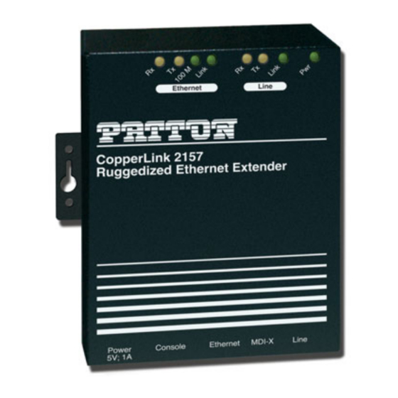
MODEL 2157R
Ruggedized CopperLink
Ethernet Extender
SALES OFFICE
(301) 975-1000
TECHNICAL SUPPORT
(301) 975-1007
Advertisement
Table of Contents

Related Manuals for Patton 2157R


Summary of Contents for Patton 2157R
- Page 1 USER MANUAL MODEL 2157R Ruggedized CopperLink Ethernet Extender This is a Class A device and is intended for use in a light industrial environment. It is not intended nor approved for use in an industrial or residential environment. Part# 07M2157R-UM SALES OFFICE Rev.
-
Page 2: Table Of Contents
A.6 Power and Power Supply Specifications ........17 A.7 Temperature Range ..............17 A.8 Humidity ..................17 A.9 Dimensions ................. 17 Model 2157R Series Factory Replacement Parts and Accessories........18 Model 2157R Series Interface Pin Assignment...... 19 C.1 10/100Base-T Interface .............. 19 RJ-45 ..................19... - Page 3 C.2 CopperLink Interface ..............19 RJ-11 ..................19...
-
Page 4: Warranty Information
1.0 WARRANTY INFORMATION Patton Electronics warrants all Model 2157R components to be free from defects, and will—at our option—repair or replace the product should it fail within one year from the first date of the shipment. This warranty is limited to defects in workmanship or materials, and does not cover customer damage, abuse or unauthorized modification. -
Page 5: Ce Declaration Of Conformity
limits for a Class A computing device in accordance with the specifica- tions in Subpart B of Part 15 of FCC rules, which are designed to provide reasonable protection from such interference in a commercial installa- tion. However, there is no guarantee that interference will not occur in a particular installation. -
Page 6: Safety When Working With Electricity
PSTN. It is intended only for connection to WARNING customer premise equipment. When the 2157R is mounted, it shall be secured in such a way as to withstand a vertical shear force of 50N or 14 pounds. -
Page 7: General Information
• Compatible with 802.1Q VLAN • LED indicators for Power; Line Link, Line Transmit, Line Receive, Ethernet Link, Ethernet 100 M, Ethernet Transmit, Ethernet Receive • Extended temperature ratings of -10 to 70C (2157R/E) and -40 to 85C (2157R/CC/E) • Made in the USA 2.2 DESCRIPTION... - Page 8 Figure 1. Typical application The 2157/L and 2157/R work together to create a transparent extension between two peered Ethernet LANs. Figure 1 shows a typical point-to- point application.
-
Page 9: Installation
See Figure 2 for the rear-panel connectors locations. • Connect the Ethernet interface (refer to section 3.2, “Line Interface— Connecting the 10/100Base-T Ethernet Interface” on page 11). • Connect the power plug (refer to section 3.3, “Connecting Power” on page 12). 2157R CopperLINK twisted-pair RJ-45 interface MDI-X... -
Page 10: Connecting The Twisted-Pair Line Interface
Follow the steps below to connect the CopperLink interfaces. Note The Model 2157R units work in pairs. One of the units must be configured as a (L) Local unit, and the other unit must be config- ured as a (R) Remote unit. It does not matter which end is the L and which is the R. -
Page 11: Line Interface-Connecting The 10/100Base-Tethernet Interface
Figure 4. CopperLink Ethernet Extender 10/100Base-T RJ-45 Connector Pinout. Connecting the 10/100Base-T Ethernet Port to a Hub or PC The Model 2157R is equipped with an MDI-X switch that enables con- nections to a hub (DCE) or PC (DTE) interface, thereby elimininating confusion over whether a straight-through or crossover cable is needed. -
Page 12: Connecting Power
An external AC or DC power supply is available separately. This connec- tion is made via the barrel jack on the rear panel of the Model 2157R. No configuration is necessary for the power supply (See Appendix B on page 19 for domestic and international power supply and cord options). -
Page 13: External Ac Universal Power Supply
Figure 8. Power connection barrel receptacle diagram • CopperLink Ethernet Extender’s rated voltage: 5.0 VDC • CopperLink Ethernet Extender’s rated current: 1 A DC External AC universal power supply • Output from power supply: 5 VDC, 2A • Input to power supply: universal input 100–240 VAC 50/60 Hz 0.3A An approved LPS external power supply that incorpo- rates a disconnect device must be used and positioned within easy reach of the operator’s position. -
Page 14: Console Port
– 6-inch cable terminated with 2.5 mm barrel plug, center positive An approved LPS external power supply that incorpo- rates a disconnect device must be used and positioned within easy reach of the operator’s position. CAUTION Connect the equipment to a 36–60 VDC source that is electrically isolated from the AC source. -
Page 15: Operation
LED status monitors. 4.1 FRONT PANEL LED STATUS MONITORS The Model 2157R features eight front-panel LEDs that monitor power, Ethernet signals, and the CopperLink connection. Figure 9 shows the front panel location of each LED. Table 1 describes the LED functions. -
Page 16: Specifications
APPENDIX A SPECIFICATIONS A.1 GENERAL CHARACTERISTICS • Compact low cost plug-and-play router • 10/100 Ethernet • Unlimited host support • Eight front panel LEDs indicate Power, WAN, Ethernet LAN speed and status • Convenient and standard RJ connectors for Ethernet and line •... -
Page 17: Extension Distance And Rate
• 4.6 Mbps speed • Distances up to 30,000 ft (9,144 m) on 24 AWG (0.4 mm) wire • Auto-adjusting rate picks best rate for a given extension distance (see tables below) Table 2: Model 2157R Extension Distances No Noise Line Rate 26g (0.4 mm) -
Page 18: Temperature Range
A.7 TEMPERATURE RANGE • -10 to 70°C (2157R/E) • -40 to 85°C (2157R/CC/E) A.8 HUMIDITY Standard:Up to 90% non-condensing Conformal Coated: 85% condensing humidity from -10 to 35°C A.9 DIMENSIONS 1.5H x 4.13W x 3.75D in.(3.81H x 10.5W x 9.53D cm) -
Page 19: Model 2157R Series Factory Replacement Parts And Accessories
2157R Base Models 2157R/EUI Ruggedized 4.6 Mbps CopperLink Ethernet Extender 2157R/EUI-2PK Ruggedized 4.6Mbps CopperLink Ethernet Extender Kit: includes one local (L) and one remote (R) Model 2157R 2157R/CC/E Extended Temperature 4.6 Mbps CopperLink Ethernet Extender 2157R/CC/E-2PK Extended Temperature 4.6 Mbps CopperLink Ethernet... -
Page 20: Model 2157R Series Interface Pin Assignment
APPENDIX C MODEL 2157R SERIES INTERFACE PIN ASSIGNMENT C.1 10/100BASE-T INTERFACE RJ-45 • Pin 1: TX+ • Pin 2: TX- • Pin 3: RX+ • Pin 6: RX- • Pins 4, 5, 7, 8: no connection C.2 COPPERLINK INTERFACE RJ-11 •... - Page 21 Notes ________________________________________________________ ________________________________________________________ ________________________________________________________ ________________________________________________________ ________________________________________________________ ________________________________________________________ ________________________________________________________ ________________________________________________________ ________________________________________________________ ________________________________________________________ ________________________________________________________ ________________________________________________________ ________________________________________________________ ________________________________________________________ ________________________________________________________ ________________________________________________________ ________________________________________________________ ________________________________________________________ ________________________________________________________ ________________________________________________________ ________________________________________________________...
- Page 22 Notes ________________________________________________________ ________________________________________________________ ________________________________________________________ ________________________________________________________ ________________________________________________________ ________________________________________________________ ________________________________________________________ ________________________________________________________ ________________________________________________________ ________________________________________________________ ________________________________________________________ ________________________________________________________ ________________________________________________________ ________________________________________________________ ________________________________________________________ ________________________________________________________ ________________________________________________________ ________________________________________________________ ________________________________________________________ ________________________________________________________ ________________________________________________________...
- Page 23 Notes ________________________________________________________ ________________________________________________________ ________________________________________________________ ________________________________________________________ ________________________________________________________ ________________________________________________________ ________________________________________________________ ________________________________________________________ ________________________________________________________ ________________________________________________________ ________________________________________________________ ________________________________________________________ ________________________________________________________ ________________________________________________________ ________________________________________________________ ________________________________________________________ ________________________________________________________ ________________________________________________________ ________________________________________________________ ________________________________________________________ ________________________________________________________...
- Page 24 Notes ________________________________________________________ ________________________________________________________ ________________________________________________________ ________________________________________________________ ________________________________________________________ ________________________________________________________ ________________________________________________________ ________________________________________________________ ________________________________________________________ ________________________________________________________ ________________________________________________________ ________________________________________________________ ________________________________________________________ ________________________________________________________ ________________________________________________________ ________________________________________________________ ________________________________________________________ ________________________________________________________ ________________________________________________________ ________________________________________________________ ________________________________________________________ Copyright © 2008 Patton Electronics Company All Rights Reserved.
Need help?
Do you have a question about the 2157R and is the answer not in the manual?
Questions and answers