Table of Contents
Advertisement
Quick Links
This is a Class A device and is intended for use in a
light industrial environment. It is not intended nor
approved for use in an industrial or residential
environment.
Part# 07M2168A-UM
Rev. A
Revised 10/8/08
An ISO-9001Certified
Company
USER
MANUAL
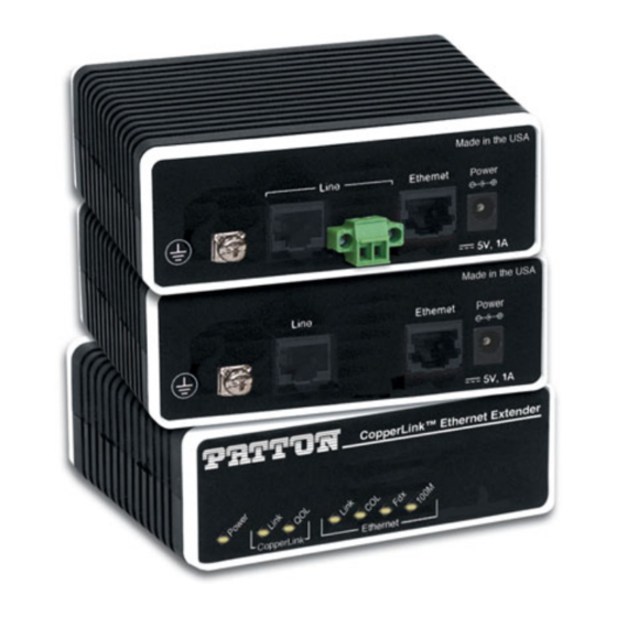
CopperLink™ Ethernet
Extenders
Models 2168A and 2158A
SALES OFFICE
(301) 975-1000
TECHNICAL SUPPORT
(301) 975-1007
Advertisement
Table of Contents

Related Manuals for Patton CopperLink E2168A


Summary of Contents for Patton CopperLink E2168A
- Page 1 USER MANUAL CopperLink™ Ethernet Extenders Models 2168A and 2158A This is a Class A device and is intended for use in a light industrial environment. It is not intended nor approved for use in an industrial or residential environment. Part# 07M2168A-UM SALES OFFICE Rev.
-
Page 2: Table Of Contents
CONTENTS Warranty Information ..............4 Compliance................... 4 EMC Compliance:................. 4 Safety Compliance: ..............4 PSTN Compliance: ............... 4 Radio and TV Interference (FCC Part 15) ........5 CE Declaration of Conformity ............5 Authorized European Representative........... 5 Service..................5 Safety When Working With Electricity .......... 6 General Information.............. - Page 3 Model 2168A and 2158A Series Factory Replacement Parts and Accessories........22 CopperLink Series Interface Pin Assignment......24 C.1 10/100Base-T Interface .............. 24 RJ-45 ..................24 C.2 CopperLink Interface ..............24 RJ-45 ..................24 Terminal Block................24 Distance Chart, Based on 24 AWG (0.5 MM) ......25...
-
Page 4: Warranty Information
1.0 WARRANTY INFORMATION Patton Electronics warrants all CopperLink Ethernet Extender compo- nents to be free from defects, and will—at our option—repair or replace the product should it fail within one year from the first date of the ship- ment. This warranty is limited to defects in workmanship or materials, and does not cover customer damage, abuse or unauthorized modification. -
Page 5: Radio And Tv Interference (Fcc Part 15)
1.2 RADIO AND TV INTERFERENCE (FCC PART 15) This equipment generates and uses radio frequency energy, and if not installed and used properly—that is, in strict accordance with the manu- facturer's instructions—may cause interference to radio and television reception. This equipment has been tested and found to comply with the limits for a Class A computing device in accordance with the specifica- tions in Subpart B of Part 15 of FCC rules, which are designed to provide reasonable protection from such interference in a commercial installa-... -
Page 6: Safety When Working With Electricity
Note Packages received without an RMA number will not be accepted. 1.6 SAFETY WHEN WORKING WITH ELECTRICITY • This device contains no user serviceable parts. The equipment shall be returned to Patton Electronics for repairs, or repaired by qualified service personnel. •... -
Page 7: General Information
2.0 GENERAL INFORMATION Thank you for your purchase of this Patton Electronics product. This product has been thoroughly inspected and tested and is warranted for one year for parts and labor. If any questions or problems arise during installation or use of this product, contact Patton Electronics Technical Support at +1 (301) 975-1007. -
Page 8: Description
2.2 DESCRIPTION The Patton Electronics CopperLink/L and CopperLink/R Ethernet Extenders provide high-speed LAN connections between peered Ether- net LANs, remote PCs, or any other network enabled 10/100Base-T device. Operating in pairs, a CopperLink/L (local) located at one end of the LAN extension and a CopperLink/R (remote) at the other end, these units can automatically forward LAN broadcasts, multicasts, and frames across a 2- wire voice-grade twisted-pair link. -
Page 9: Installation
3.0 INSTALLATION Because the CopperLink Ethernet Extender requires no configuration, it can be installed quickly. Note If asymmetric transmission or line rates other than 12.5 Mbps are required , refer to section 4.0, “Configuration” on page 16. 3.1 UNIT INSTALLATION Do the following: 1. -
Page 10: Grounding The Copperlink Ethernet Extender
3.2 GROUNDING THE COPPERLINK ETHERNET EXTENDER Before installing the CopperLink Ethernet Extender, it is important to establish a good grounding connection first. 1. Assemble a ground wire using #10 AWG wire with green-and-yel- low-colored insulation and two ring terminals. Make the wire long enough to reach one of the following earth ground sources: —... - Page 11 The RJ-45 connector on the CopperLink Ethernet Extender's twisted pair interface is polarity insensitive and is wired for a two-wire inter- face. The signal/pin relationship is shown in Figure 3. 1 (no connection) 2 (no connection) 3 (no connection) 4 (2-Wire RING) 5 (2-Wire TIP) 6 (no connection) 7 (no connection)
-
Page 12: Using A Ferrite Clamp To Connect The Line Interface
Using a Ferrite Clamp to Connect the Line Interface • The ferrite clamp that is shipped with the unit must be used as detailed in the following instructions in order to meet EMC requirements. WARNING Connecting the ferrite clamp to the RJ-45 port. To connect the ferrite clamp to the RJ-45 port: 1. -
Page 13: Connecting The Ferrite Clamp To The Terminal Block
Connecting the ferrite clamp to the terminal block. To connect the ferrite clamp to the terminal block: 1. Place the cable inside the ferrite clamp, leaving about 1-2 inches of cable between the unit and clamp. 2. Wrap the cable tightly around the clamp two times and secure the wire firmly in the clamp channel. -
Page 14: Connecting The 10/100Base-T Ethernet Interface
3.4 CONNECTING THE 10/100BASE-T ETHERNET INTERFACE The RJ-45 port labeled Ethernet is the Auto-MDIX10/100Base-T inter- face. This port is designed to connect directly to a 10/100Base-T net- work. Figure 7 shows the signal/pin relationships on this interface. You may connect this port to a hub or PC using a straight through or cross- over cable that is up to 328 ft long. -
Page 15: Connecting Power
3.5 CONNECTING POWER • Do not connect power to the DC Mains at this time. • There are no user-serviceable parts in the power supply sec tion of the CopperLink Ethernet Extender. Contact Patton Elec- WARNING tronics Technical support at (301)975-1007, via our web site at http://www.patton.com, or by e-mail at support@pat- ton.com, for more information. -
Page 16: Configuration
4.0 CONFIGURATION The CopperLink Models 2168A and 2168A/TB45 have an eight-position DIP switch for configuring the unit for a wide variety of applications. This section describes switch locations and explains the different configura- tions. The Model 2158A does not include dip switches. 4.1 CONFIGURING THE HARDWARE DIP SWITCHES Using a small flat-tip screwdriver, remove the protective cover located on the underside of the CopperLink Ethernet Extender (see Figure 8). -
Page 17: Configuring Dip Switch Sw
4.2 CONFIGURING DIP SWITCH SW DIP switch SW is where you configure the CopperLink line rate, and if the rate is symmetric or asymmetric. Switches SW-2 and SW-4: Data Rate Use switches SW-2 and SW-4 to configure the CopperLink line rates. Table 1: Symmetric CopperLink Line Rates Selection Chart SW-2 SW-3... -
Page 18: Operation
5.0 OPERATION Once the CopperLink Ethernet Extenders are properly installed, they should operate transparently. No user settings required. This section describes reading the LED status monitors. 5.1 POWER UP Before applying power to the CopperLink Ethernet Extender, please review section 3.5, “Connecting Power” on page 15 to verify that the unit is connected to the appropriate power source. - Page 19 Table 4: Front panel LED description for the 2168A Description Power On (green) when power is applied to the unit. Off when no power is applied to the unit. CopperLink - On (green) when the end-to-end CopperLink link Link between the units is established. Off when the link has not been established or when the link fails CopperLink - Flashes yellow at different rates to indicate the...
-
Page 20: Specifications
APPENDIX A SPECIFICATIONS A.1 LAN CONNECTION • Unshielded RJ-45, 10/100Base-T, IEEE 802.3 Ethernet • CopperLink Connection: — 2168A/TB45: RJ-45 and Terminal Block — 2168A/2158A: RJ-45 only A.2 TRANSMISSION LINE Two-wire unconditioned twisted pair. A.3 COPPERLINK LINE RATE 16.67 Mbps (Model 2168A and Model 2168A/TB45) and 12.55 Mbps (Model 2158A) symmetric upstream/downstream. -
Page 21: Power Supply
A.7 POWER SUPPLY Input power: 5 VDC, 1A Power consumption: 560 mA at 5 VDC (typical) External AC and DC options: • AC: 120 VAC, 220 VAC, and UI (120–240 VAC) • DC: 12 VDC, 24 VDC and 48 VDC Internal 36-72VDC (nominal 48V) Terminal Block Plug (1x3, 3.81mm, with screws) Pin Header Socket Connector A.8 TEMPERATURE RANGE... -
Page 22: Model 2168A And 2158A Series Factory Replacement Parts And Accessories
APPENDIX B MODEL 2168A AND 2158A SERIES FACTORY REPLACEMENT PARTS AND ACCESSORIES Patton Model # Description Base Models 2168A/L/EUI Local Multi Rate CopperLink Ethernet Extender with RJ-45 connec- tor, 120-240VAC 2168A/R/EUI Remote Multi Rate CopperLink Ethernet Extender with RJ-45 con- nector, 120-240VAC 2168A/L/TB45/EUI Local Multi Rate CopperLink Ethernet Extender with terminal block,... - Page 23 Patton Model # Description 2158A/EI-2PK Fixed Rate CopperLink Ethernet Extender Kit: includes one local (L) and one remote (R) CopperLink Ethernet Extender; with terminal block and RJ45 07M2168A-UM User Manual Power Supplies 08055DCUI 100-240VAC (+5V reg. DC/2A) Universal Input Adapter. 08055-120-5-1 120 VAC (+5V reg.
-
Page 24: Copperlink Series Interface Pin Assignment
APPENDIX C COPPERLINK SERIES INTERFACE PIN ASSIGNMENT C.1 10/100BASE-T INTERFACE RJ-45 • Pin 1: TX+/RX+ • Pin 2: TX-/RX- • Pin 3: RX+/TX+ • Pin 6: RX-/TX- • Pins 4, 5, 7, 8: no connection C.2 COPPERLINK INTERFACE RJ-45 • Pin 4: RING •... -
Page 25: Distance Chart, Based On 24 Awg (0.5 Mm)
APPENDIX D DISTANCE CHART, BASED ON 24 AWG (0.5 MM) Symm Line Rate Distance in feet (km) 6.25 Mbps 4,500 (1.37) 9.38 Mbps 4,150 (1.26) 4,000 (1.22) 12.5 Mbps 16.67 Mbps 3,300 (1.00) *. This is the only option available for Model 2158A. - Page 26 NOTES _________________________________________________________ _________________________________________________________ _________________________________________________________ _________________________________________________________ _________________________________________________________ _________________________________________________________ _________________________________________________________ _________________________________________________________ _________________________________________________________ _________________________________________________________ _________________________________________________________ _________________________________________________________ _________________________________________________________ _________________________________________________________ _________________________________________________________ _________________________________________________________...
- Page 27 NOTES _________________________________________________________ _________________________________________________________ _________________________________________________________ _________________________________________________________ _________________________________________________________ _________________________________________________________ _________________________________________________________ _________________________________________________________ _________________________________________________________ _________________________________________________________ _________________________________________________________ _________________________________________________________ _________________________________________________________ _________________________________________________________ _________________________________________________________ _________________________________________________________...
- Page 28 NOTES _________________________________________________________ _________________________________________________________ _________________________________________________________ _________________________________________________________ _________________________________________________________ _________________________________________________________ _________________________________________________________ _________________________________________________________ _________________________________________________________ _________________________________________________________ _________________________________________________________ _________________________________________________________ _________________________________________________________ Copyright © 2008 Patton Electronics Company All Rights Reserved.