Table of Contents
Advertisement
Quick Links
REGULATORY MODEL NUMBER:
03342D4-001
This is a Class A device and is not intended for
use in a residential environment.
An ISO-9001Certified
Company
Part# 07M2174-UM
Rev. D
Revised 7/5/12
USER
MANUAL
MODEL 2174
CopperLINK™ High Speed
Ethernet Extender
SALES OFFICE
(301) 975-1000
TECHNICAL SUPPORT
(301) 975-1007
Advertisement
Table of Contents

Related Manuals for Patton CopperLINK 2174


Summary of Contents for Patton CopperLINK 2174
- Page 1 USER MANUAL MODEL 2174 CopperLINK™ High Speed Ethernet Extender REGULATORY MODEL NUMBER: 03342D4-001 This is a Class A device and is not intended for use in a residential environment. SALES OFFICE Part# 07M2174-UM Rev. D (301) 975-1000 Revised 7/5/12 TECHNICAL SUPPORT...
-
Page 2: Table Of Contents
Description..................8 Installation................... 9 Connecting the Line Interface............. 11 Connecting the Line Interface for Model 2174/EUI or 2174/TB.. 11 Connecting the Line Interface for Model 2174/BNC ....12 Connecting the 10/100Base-T Ethernet Interface ...... 12 Connecting the POTS/ISDN Line (2174/S)......... 13 Connecting Power .............. - Page 3 C.1 10/100Base-T Interface .............. 19 RJ-45 ..................19 C.2 CopperLINK Interface ..............19 RJ-45 ..................19 Terminal Block................19 C.3 POTS/ISDN Interface (2174/S) ............ 19 RJ-45 ..................19 Line Rate & Reach Chart, Based on 24 AWG (0.5 MM) ..20...
-
Page 4: Warranty Information
Under no condition shall Patton Electronics be liable for any damages incurred by the use of this product. These damages include, but are not limited to, the following: lost profits, lost savings and incidental or consequential damages arising from the use of or inability to use this product. -
Page 5: Ce Declaration Of Conformity
AC outlet (such that the computing equipment and receiver are on different branches). 1.3 CE DECLARATION OF CONFORMITY Patton Electronics, Inc declares that this device is in compliance with the essential requirements and other relevant provisions of Directive 2004/108/EC relating to electromagnetic compatibility and Directive 2006/95/EC relating to electrical equipment designed for use within cer- tain voltage limits. -
Page 6: Safety When Working With Electricity
1.6 SAFETY WHEN WORKING WITH ELECTRICITY • This device contains no user serviceable parts. This device can only be repaired by qualified service per- sonnel. • Do not open the device when the power cord is con- nected. For systems without a power switch and without an external power adapter, line voltages are present within the device when the power cord is connected. - Page 7 In accordance with the requirements of council direc- tive 2002/96/EC on Waste of Electrical and Electronic Equipment (WEEE), ensure that at end-of-life you sepa- rate this product from other waste and scrap and deliver to the WEEE collection system in your country for recy- cling.
-
Page 8: General Information
Operating in pairs, one Model 2174 is configured as the (L) Local unit located at one end of the LAN extension and the other Model 2174 is con- figured as the (R) Remote unit at the other end. The Model 2174 is config- ured as a L or R via the switch on the bottom of the unit. -
Page 9: Installation
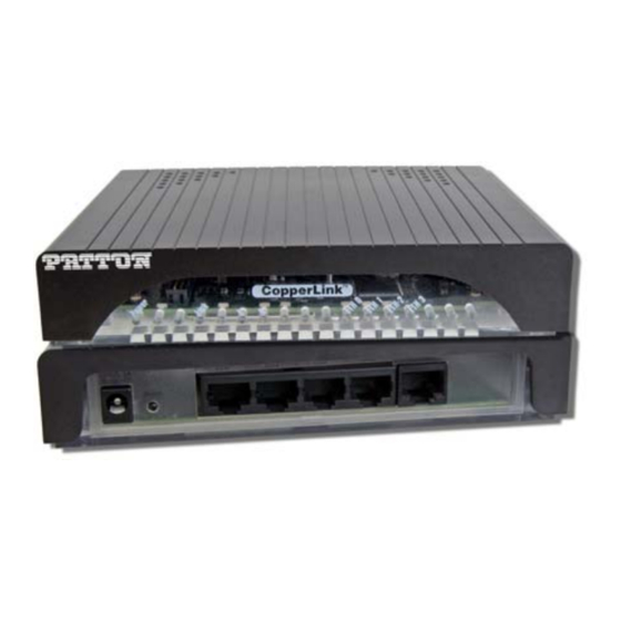
Figure 1. Typical application The pair of 2174 models work together to create a transparent extension between two peered Ethernet LANs using twisted pair (2-wire), Cat5+, or 75-ohm BNC. Figure 1 shows a typical point-to-point application. 3.0 INSTALLATION The Interconnecting cables shall be acceptable for... - Page 10 Figure 2. Model 2174 rear panel options...
-
Page 11: Connecting The Line Interface
19 (0.9mm) and 26 AWG (0.4mm). Leased circuits that run through signal equalization equipment are not acceptable. 2. The Model 2174 is equipped with an RJ-45 interface jack (Figure 3) or terminal block (Figure 4) that can be used on the CopperLINK inter- face. -
Page 12: Connecting The Line Interface For Model 2174/Bnc
Figure 4. Model 2174 (Terminal Block) twisted pair line interface Connecting the Line Interface for Model 2174/BNC To connect the line interface of the Model 2174/BNC, simply use a coax- ial cable with a BNC connector at each end to connect the pair of Model 2174s. -
Page 13: Connecting The Pots/Isdn Line (2174/S)
An external AC or DC power supply is available separately. This connec- tion is made via the barrel jack on the rear panel of the Model 2174. No configuration is necessary for the power supply (See Appendix B for domestic and international power supply and cord options). -
Page 14: Configuration
4.0 CONFIGURATION The Model 2174 has eight DIP switches (S1) for configuring the unit for a wide variety of applications. This section describes switch locations and explains the different configurations. 4.1 CONFIGURING THE HARDWARE DIP SWITCHES The DIP switches are externally accessible from the underside of the Model 2174. -
Page 15: Switch S1-1: Local/Remote Configuration
Switch S1-1: Local/Remote Configuration Use switch S1-1 to configure the unit as Remote or Local in the Model 2174 pair. Table 2: Local/Remote Unit Configuration S1-1 Setting CPE/Remote CO/Local Switches S1-2 and S1-3: Symmetric/Asymmetric Operation Use switches S1-2 and S1-3 to configure the CopperLink line rate type- and operation. -
Page 16: Operation
5.1 FRONT PANEL LED STATUS MONITORS The Model 2174 features six front panel LEDs that monitor power, the Ethernet signals, the CopperLINK connection, and the remote/local set- ting. Figure 8 shows the front panel location of each LED. Table 5 on page 16 describes the LED functions. -
Page 17: Specifications
APPENDIX A SPECIFICATIONS A.1 LAN CONNECTION • Four RJ-45, 10/100Base-T, IEEE 802.3 Ethernet • CopperLINK Connection: RJ-45 A.2 TRANSMISSION LINE Two-wire unconditioned twisted pair or 75-ohm BNC A.3 COPPERLINK LINE RATE AND COPPERLINK DISTANCE • Line Rate: Up to 200 Mbps asymmetrical •... -
Page 18: Model 2174 Series Factory
APPENDIX B MODEL 2174 SERIES FACTORY REPLACEMENT PARTS AND ACCESSORIES Patton Model # Description Base Models 2174/EUI-2PK High Speed CopperLink Ethernet Extender Kit (Local and Remote); RJ45 Line, 100-240VAC 2174/TB/EUI-2PK High Speed CopperLink Ethernet Extender Kit (Local and Remote); Terminal Block Line, 100-240VAC... -
Page 19: Model 2174 Series Interface Pin Assignment
APPENDIX C MODEL 2174 SERIES INTERFACE PIN ASSIGNMENT C.1 10/100BASE-T INTERFACE RJ-45 • Pin 1: TX+ • Pin 2: TX- • Pin 3: RX+ • Pin 6: RX- • Pins 4, 5, 7, 8: no connection C.2 COPPERLINK INTERFACE RJ-45 •... -
Page 20: Line Rate & Reach Chart, Based On 24 Awg (0.5 Mm)
The actual distance and link performance may vary depending on the environment and type/gauge of wire used. Note DS = downstream, US = upstream Note This chart applies to Model 2174s with a twisted-pair line inter- face: Model 2174/EUI and 2174/TB. Contact Patton for Model 2174/BNC rates. - Page 21 The actual distance and link performance may vary depending on the environment and type/gauge of wire used. Note DS = downstream, US = upstream Note This chart applies to Model 2174s with a twisted-pair line inter- face: Model 2174/EUI and 2174/TB. Contact Patton for Model 2174/BNC rates.
- Page 22 _________________________________________________________ _________________________________________________________ _________________________________________________________ _________________________________________________________ _________________________________________________________ _________________________________________________________ _________________________________________________________ _________________________________________________________ _________________________________________________________ _________________________________________________________ _________________________________________________________ _________________________________________________________ _________________________________________________________ _________________________________________________________...
- Page 23 _________________________________________________________ _________________________________________________________ _________________________________________________________ _________________________________________________________ _________________________________________________________ _________________________________________________________ _________________________________________________________ _________________________________________________________ _________________________________________________________ _________________________________________________________ _________________________________________________________ _________________________________________________________ _________________________________________________________ _________________________________________________________...
- Page 24 Copyright © 2011-2012. Patton Electronics Company All Rights Reserved.
Need help?
Do you have a question about the CopperLINK 2174 and is the answer not in the manual?
Questions and answers