Table of Contents
Advertisement
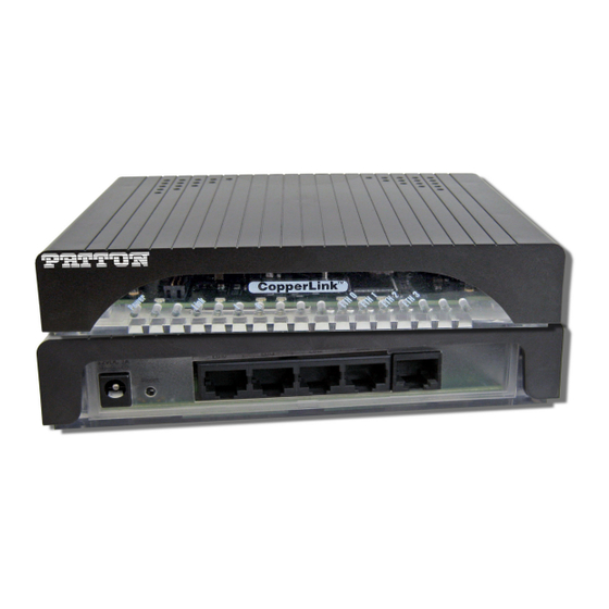
CopperLink™ Model 1214
High Speed Ethernet Extender
User Manual
This is a Class A device and is not intended for use in a residential environment.
Sales Office:
+1 (301) 975-1000
Technical Support:
+1 (301) 975-1007
E-mail:
support@patton.com
WWW:
www.patton.com
Part Number: 07MCL1214-UM, Rev. C
Revised: October 9, 2014
Advertisement
Table of Contents

Related Manuals for Patton CopperLink 1214


Summary of Contents for Patton CopperLink 1214
-
Page 1: User Manual
User Manual This is a Class A device and is not intended for use in a residential environment. Sales Office: +1 (301) 975-1000 Technical Support: +1 (301) 975-1007 E-mail: support@patton.com WWW: www.patton.com Part Number: 07MCL1214-UM, Rev. C Revised: October 9, 2014... - Page 2 Under no condition shall Patton Electronics be liable for any damages incurred by the use of this product. These damages include, but are not limited to, the following: lost profits, lost savings and incidental or consequential damages arising from the use of or inability to use this product.
-
Page 3: Summary Table Of Contents
Summary Table of Contents General information ............................12 Installation ................................ 14 Configuration ..............................19 4 Operation................................22 Contacting Patton for assistance......................... 24 Compliance information ........................... 27 Specifications ..............................30 Factory Replacement Parts and Accessories ......................32 Interface Pin Assignment ..........................34 Line Rate &... -
Page 4: Table Of Contents
......................20 Configuring the Hardware DIP switches ..........................20 Configuring DIP Switch S1 4 Operation................................22 ................................23 Introduction ........................23 Front Panel LED Status Monitors Contacting Patton for assistance......................... 24 ................................25 Introduction Contact information..............................25 Warranty Service and Returned Merchandise Authorizations (RMAs)..............25 ............................25 Warranty coverage ..............................26... - Page 5 CopperLink 1214 User Manual Table of Contents Specifications ..............................30 Connection..............................31 ..............................31 Transmission Line ............................31 LED Status Indicators ................................31 Power Supply ......................31 External AC and Internal DC options: .................................31 Physical ........................31 Operating Temperature Range ................................31 Humidity ..............................31 Dimensions Factory Replacement Parts and Accessories ......................
-
Page 6: List Of Figures
List of Figures Typical application ..............13 CL1214 rear panel options . -
Page 7: List Of Tables
List of Tables S1 Summary ................20 Local/Remote Unit Configuration . -
Page 8: About This Guide
Appendix E on page 36 provides a line range and reach chart for the CL1214 For best results, read the contents of this guide before you install the CopperLink 1214. Precautions Notes and cautions, which have the following meanings, are used throughout this guide to help you become aware of potential Router modem problems. - Page 9 CopperLink 1214 User Manual About This Guide The shock hazard symbol and CAUTION heading indicate a potential electric shock hazard. Strictly follow the instructions to avoid property damage caused by electric shock. CAUTION The alert symbol and WARNING heading indicate a potential safety hazard.
-
Page 10: Safety When Working With Electricity
CopperLink 1214 User Manual About This Guide Safety When Working With Electricity • This device contains no user serviceable parts. This device can only be repaired by qualified service person- nel. WARNING • Do not open the device when the power cord is con- nected. - Page 11 CopperLink 1214 User Manual About This Guide This device contains no user serviceable parts. This device can only be repaired by qualified service personnel. WARNING This device is NOT intended nor approved for connection to the PSTN. It is intended only for connection to customer premise equipment.
-
Page 12: General Information
Chapter 1 General information Chapter contents Overview ................................13 Features ................................13 Description ..............................13... -
Page 13: Overview
1 • General information Overview Thank you for your purchase of this Patton Electronics product. This product has been thoroughly inspected and tested and is warranted for one year for parts and labor. If any questions or problems arise during installa- tion or use of this product, contact Patton Electronics Technical Support at +1 (301) 975-1007. -
Page 14: Installation
Chapter 2 Installation Chapter contents Planning the Installation............................15 Connecting the Line Interface ..........................16 Connecting the Line Interface for CL1214/EUI or CL1214/TB ...............16 Connecting the Line Interface for CL1214/BNC ..................17 Connecting the 10/100Base-T Ethernet Interface ...................17 Connecting the POTS/ISDN Line (CL1214/S) ....................17 Connecting Power ..............................18... -
Page 15: Planning The Installation
CopperLink 1214 User Manual 2 • Installation Planning the Installation The Interconnecting cables shall be acceptable for external use and shall be rated for the proper application with respect to volt- age, current, anticipated temperature, flammability, and CAUTION mechanical serviceability. -
Page 16: Connecting The Line Interface
CopperLink 1214 User Manual 2 • Installation Connecting the Line Interface The interconnecting cables shall be acceptable for external use and shall be rated for the proper application with respect to volt- age, current, anticipated temperature, flammability, and CAUTION mechanical serviceability. -
Page 17: Connecting The 10/100Base-T Ethernet Interface
CopperLink 1214 User Manual 2 • Installation RING Figure 4. CL1214 (Terminal Block) twisted pair line interface Connecting the Line Interface for CL1214/BNC To connect the line interface of the CL1214/BNC, simply use a coaxial cable with a BNC connector at each end to connect the pair of CL1214s. -
Page 18: Connecting Power
CopperLink 1214 User Manual 2 • Installation Connecting the POTS/ISDN Line (CL1214/S) On the CL1214/S model, the RJ-45 port labeled is the POTS/ISDN interface. A telephone may be con- nected to this port and carried over the CopperLink line. The units do not need power for the POTS interface to work. -
Page 19: Configuration
Chapter 3 Configuration Chapter contents Introduction ................................20 Configuring the Hardware DIP switches ......................20 Configuring DIP Switch S1 ..........................20 Switch S1-1: Local/Remote Configuration ....................21 Switches S1-2 and S1-3: Symmetric/Asymmetric Operation ..............21 Switch S1-5: General Protection (Signal to Noise Ratio) ................21... -
Page 20: Introduction
CopperLink 1214 User Manual 3 • Configuration Introduction The CL1214 has eight DIP switches (S1) for configuring the unit for a wide variety of applications. This sec- tion describes switch locations and explains the different configurations. Configuring the Hardware DIP switches The DIP switches are externally accessible from the underside of the CL1214. -
Page 21: Local/Remote Unit Configuration
CopperLink 1214 User Manual 3 • Configuration Switch S1-1: Local/Remote Configuration Use switch S1-1 to configure the unit as Remote or Local in the CL1214 pair. Table 2. Local/Remote Unit Configuration S1-1 Setting CPE/Remote CO/Local Switches S1-2 and S1-3: Symmetric/Asymmetric Operation Use switches S1-2 and S1-3 to configure the CopperLink line rate type and operation. -
Page 22: Operation
Chapter 4 Operation Chapter contents Introduction ................................23 Front Panel LED Status Monitors ........................23... -
Page 23: Introduction
CopperLink 1214 User Manual 4 • Operation Introduction Once the CL1214s are properly installed, they should operate transparently. No user settings required. This section describes reading the LED status monitors. Before applying power to the CL1214, please review “Connecting Power”... -
Page 24: Contacting Patton For Assistance
Chapter 5 Contacting Patton for assistance Chapter contents Introduction ................................25 Contact information..............................25 Warranty Service and Returned Merchandise Authorizations (RMAs)..............25 Warranty coverage ............................25 Out-of-warranty service ..........................25 Returns for credit ............................25 Return for credit policy ..........................26 RMA numbers ..............................26 Shipping instructions ..........................26... -
Page 25: Introduction
If you have ordered the wrong equipment or you are dissatisfied in any way, please contact us to request an RMA number to accept your return. Patton is not responsible for equipment returned without a Return Authorization. -
Page 26: Rma Numbers
RMA#: xxxx 7622 Rickenbacker Dr. Gaithersburg, MD 20879-4773 USA Patton will ship the equipment back to you in the same manner you ship it to us. Patton will pay the return shipping costs. Warranty Service and Returned Merchandise Authorizations (RMAs) -
Page 27: Compliance Information
Appendix A Compliance information Chapter contents Regulatory Information ............................28 EMC Directive: ..............................28 Low-Voltage Directive (Safety): ........................28 PSTN: ................................28 Radio and TV Interference (FCC Part 15) ......................28 CE Declaration of Conformity ..........................28 Authorized European Representative ........................28 Service ...................................29... -
Page 28: Regulatory Information
CE Declaration of Conformity Patton Electronics, Inc declares that this device is in compliance with the essential requirements and other rele- vant provisions of Directive 2004/108/EC relating to electromagnetic compatibility and Directive 2006/95/ EC relating to electrical equipment designed for use within certain voltage limits. -
Page 29: Service
A • Compliance information Service All warranty and non-warranty repairs must be returned freight prepaid and insured to Patton Electronics. All returns must have a Return Materials Authorization number on the outside of the shipping container. This number may be obtained from Patton Electronics Technical Services at: •... -
Page 30: Specifications
Appendix B Specifications Chapter contents Connection..............................31 Transmission Line ..............................31 LED Status Indicators ............................31 Power Supply ................................31 External AC and Internal DC options: ......................31 Physical .................................31 Operating Temperature Range ........................31 Humidity ................................31 Dimensions ..............................31... -
Page 31: Lan Connection
CopperLink 1214 User Manual B • Specifications LAN Connection • Four RJ-45, 10/100Base-T, IEEE 802.3 Ethernet • CopperLink Connection: RJ-45 Transmission Line Two-wire unconditioned twisted pair or 75-ohm BNC LED Status Indicators • Power (Green) • CopperLink: Link (Green) •... -
Page 32: Factory Replacement Parts And Accessories
Appendix C Factory Replacement Parts and Accessories Chapter contents CL1214 Series Factory Replacement Parts and Accessories ..................33... -
Page 33: Cl1214 Series Factory Replacement Parts And Accessories
CopperLink 1214 User Manual C • Factory Replacement Parts and Accessories CL1214 Series Factory Replacement Parts and Accessories Patton Model # Description Base Models CL1214/EUI-2PK High Speed CopperLink Ethernet Extender Kit (Local and Remote); RJ45 Line, 100-240VAC CL1214/TB/EUI-2PK High Speed CopperLink Ethernet Extender Kit (Local and Remote); Ter- minal Block Line, 100-240VAC CL1214/BNC/EUI-2PK High Speed CopperLink Ethernet Extender Kit (Local and Remote);... -
Page 34: Interface Pin Assignment
Appendix D Interface Pin Assignment Chapter contents 10/100Base-T Interface ............................35 CopperLink Interface ............................35 POTS/ISDN Interface (CL1214/S)........................35... -
Page 35: 10/100Base-T Interface
CopperLink 1214 User Manual D • Interface Pin Assignment 10/100Base-T Interface RJ-45 • Pin 1: TX+ • Pin 2: TX- • Pin 3: RX+ • Pin 6: RX- • Pins 4, 5, 7, 8: no connection CopperLink Interface RJ-45 •... -
Page 36: Line Rate & Reach Chart
Appendix E Line Rate & Reach Chart Chapter contents Line Rate & Reach Chart Based on 24 AWG (0.5 mm) ..................37... -
Page 37: Line Rate & Reach Chart Based On 24 Awg (0.5 Mm)
DS = downstream, US = upstream Note This chart applies to CL1214s with a twisted-pair line interface: CL1214/ EUI and CL1214/TB. Contact Patton for CL1214/BNC rates. Table 7. Line Rate & Reach Chart Using Twisted-Pair (High Speed) Distance in Feet... - Page 38 CopperLink 1214 User Manual E • Line Rate & Reach Chart Line Rate & Reach Chart Based on 24 AWG (0.5 mm)
Need help?
Do you have a question about the CopperLink 1214 and is the answer not in the manual?
Questions and answers