
Related Manuals for Patton 2158


Summary of Contents for Patton 2158
- Page 1 USER MANUAL MODEL 2158 CopperLink Ethernet Extender Part# 07M2158-A SALES OFFICE Doc# 058092UA (301) 975-1000 Revised 10/15/01 TECHNICAL SUPPORT (301) 975-1007 An ISO-9001Certified Company...
-
Page 2: Table Of Contents
A.10 Temperature Range ..............13 A.11 Humidity ..................13 A.12 Dimensions ..................13 Model 2158 Series Factory Replacement Parts and Accessories........14 Model 2158 Series Interface Pin Assignment ......15 C.1 10/100Base-T Interface: ..............15 RJ-45 ..................15 C.2 CopperLink Interface: ..............15 RJ-45 ..................15... -
Page 3: Warranty Information
The Model 2158 has been tested and found to comply with the limits for a Class A computing device in accordance with specifications in Sub- part B of Part 15 of FCC rules, which are designed to provide reasonable protection from such interference in a commercial installation. -
Page 4: Ce Notice
1.2 CE NOTICE The CE symbol on your Patton Electronics equipment indicates that it is in compliance with the Electromagnetic Compatibility (EMC) directive and the Low Voltage Directive (LVD) of the European Union (EU). A Cer- tificate of Compliance is available by contacting Technical Support. -
Page 5: General Information
LANs, remote PC’s, or any other network enabled 10/100Base-T device. Operating in pairs with a Model 2158/L (Local) located at one end of the LAN connection, and a Model 2158/R (Remote) at the other end, can automatically forward LAN broadcasts, multi-casts and frames across a 2-wire twisted pair link. -
Page 6: Typical Application
2.3 TYPICAL APPLICATION Figure 1. Typical application The 2158/L and 2158/R work together to create a transparent extension between two peered Ethernet LANs. Figure 1 shows a typical application. -
Page 7: Installation
3.0 INSTALLATION Because the Model 2158 requires no configuration, it can be installed and made operational quickly. Installation takes place as follows: 1. Connecting the line interface between the units (refer to section 3.1, “Connecting the Twisted-Pair Line Interface” on page 7) Note See Figure 2 for the rear panel arrangements. - Page 8 Note The Model 2158 units work in pairs. One of the units must be a Model 2158/L (Local), and the other unit must be a Model 2158/ R (Remote). It does not matter which end is the 2158/L and which is the 2158/R.
-
Page 9: Connecting The 10/100Base-T Ethernet Interface
Figure 5. Model 2158 10/100Base-T RJ-45 Connector Pinout. Connecting the 10/100Base-T Ethernet Port to a Hub The Model 2158 10/100Base-T interface is configured as DTE (Data Ter- minal Equipment), just like a 10/100Base-T network interface card in a PC. Therefore, it "expects" to connect to a 10/100Base-T Hub using a... -
Page 10: Connecting The 10/100Base-T Ethernet Port To A Pc (Dte)
3.3 CONNECTING POWER An external AC or DC power supply is available separately. This connec- tion is made via the barrel jack on the rear panel of the Model 2158. No configuration is necessary for the power supply (See Appendix B for domestic and international power supply and cord options). -
Page 11: Operation
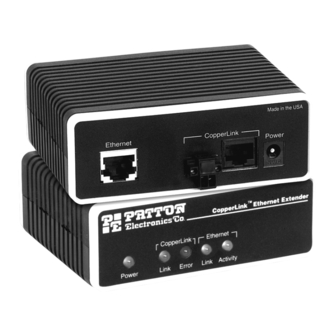
4.2 FRONT PANEL LED STATUS MONITORS The Model 2158 features five front panel LEDs that monitor power, the Ethernet signals, and the CopperLink Connection. Figure 8 shows the front panel location of each LED. Table 1 on page 12 describes the LED functions. - Page 12 The CopperLink LED is OFF when the link is down. Link is always initiated by the remote unit (Model 2158/R). As long as the local unit (Model 2158/L) is powered on, the remote unit (Model 2158/ R) can establish a link by being powered on or restarting power.
-
Page 13: Specifications
APPENDIX A SPECIFICATIONS A.1 LAN CONNECTION Shielded RJ-45, 10/100Base-T, IEEE 802.3 Ethernet A.2 COPPERLINK CONNECTION RJ-45 and Terminal Block A.3 TRANSMISSION LINE Two-wire unconditioned twisted pair A.4 COPPERLINK LINE RATE 12.5 Mbps, symmetric upstream/downstream. A.5 ACTUAL DATA RATE 10 Mbps, symmetric upstream/downstream. A.6 COPPERLINK DISTANCE 4,000 ft (1,219 m) A.7 COPPERLINK SURGE SUPPRESSOR... -
Page 14: B Model 2158 Series Factory
CopperLink Ethernet Extender; Line: RJ-45 & TB (Local) 2158/R CopperLink Ethernet Extender; Line: RJ-45 & TB (Remote) 2158-2PK CopperLink Ethernet Extender Kit: includes one local (L) and one remote (R) Model 2158 07m2158 User Manual Power Supplies 08055DCUI 100-240VAC (+5V reg. DC/2A) Universal Input Adapter. -
Page 15: Model 2158 Series Interface Pin Assignment
APPENDIX C MODEL 2158 SERIES INTERFACE PIN ASSIGNMENT C.1 10/100BASE-T INTERFACE: RJ-45 • Pin 1: TX+ • Pin 2: TX- • Pin 3: RX+ • Pin 6: RX- • Pins 4, 5, 7, 8: no connection C.2 COPPERLINK INTERFACE: RJ-45 •... - Page 16 Copyright © 2001 Patton Electronics Company All Rights Reserved.
Need help?
Do you have a question about the 2158 and is the answer not in the manual?
Questions and answers