Patton CopperLink 1211 User Manual

Patton CopperLink 1211 User Manual

High speed ethernet extender
Table of Contents

Advertisement

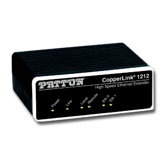
CopperLink™ Model 1211/1212
High Speed Ethernet Extender

User Manual

This is a Class A device and is not intended for use in a residential environment.
Sales Office:
+1 (301) 975-1000
Technical Support:
+1 (301) 975-1007
E-mail:
support@patton.com
WWW:
www.patton.com
Part Number: 07MCL1212-UM, Rev. C
Revised: December 12, 2014

Advertisement

Table of Contents
loading

Summary of Contents for Patton CopperLink 1211

  • Page 1: User Manual

    User Manual This is a Class A device and is not intended for use in a residential environment. Sales Office: +1 (301) 975-1000 Technical Support: +1 (301) 975-1007 E-mail: support@patton.com WWW: www.patton.com Part Number: 07MCL1212-UM, Rev. C Revised: December 12, 2014...
  • Page 2 Under no condition shall Patton Electronics be liable for any damages incurred by the use of this product. These damages include, but are not limited to, the following: lost profits, lost savings and incidental or consequential damages arising from the use of or inability to use this product.
  • Page 3: Summary Table Of Contents

    Summary Table of Contents General information ............................12 Installation ................................ 15 Configuration ..............................20 4 Operation................................24 Contacting Patton for assistance......................... 26 Compliance Information ........................... 29 Specifications ..............................32 Factory Replacement Parts and Accessories ......................34 Interface Pin Assignment ..........................36 Line Rate &...
  • Page 4: Table Of Contents

    Switches S1-2 and S1-3: Symmetric/Asymmetric Operation .................23 Switch S1-5: General Protection (Signal to Noise Ratio) 4 Operation................................24 ................................25 Introduction .........................25 Front Panel LED Status Monitors Contacting Patton for assistance......................... 26 ................................27 Introduction Contact information..............................27 Warranty Service and Returned Merchandise Authorizations (RMAs)..............27 ............................27...
  • Page 5 CopperLink 1211/1212 User Manual ........................30 Low-Voltage Directive (Safety): ................................30 PSTN: ......................30 Radio and TV Interference (FCC Part 15) ..........................30 CE Declaration of Conformity ........................30 Authorized European Representative ...................................31 Service Specifications ..............................32 ..............................33 Line Connector ..............................33 LAN Connectors ..............................33 Transmission Line ............................33...
  • Page 6: List Of Figures

    List of Figures Typical applications ..............14 CL1212 rear panel options .
  • Page 7: List Of Tables

    List of Tables S1 Summary ................22 Local/Remote Unit Configuration .
  • Page 8: About This Guide

    CopperLink 1211/1212 User Manual About This Guide About This Guide This guide describes the CopperLink Model 1211/1212 hardware, installation, and basic configuration. Audience This guide is intended for the following users: • Operators • Installers • Maintenance technicians Structure This guide contains the following chapters and appendices: •...
  • Page 9 CopperLink 1211/1212 User Manual About This Guide The alert symbol and CAUTION heading indicate a potential hazard. Strictly follow the instructions to avoid property dam- age. CAUTION The shock hazard symbol and CAUTION heading indicate a potential electric shock hazard. Strictly follow the instructions to avoid property damage caused by electric shock.
  • Page 10: Safety When Working With Electricity

    CopperLink 1211/1212 User Manual About This Guide Safety When Working With Electricity • This device contains no user serviceable parts. This device can only be repaired by qualified service person- nel. WARNING • Do not open the device when the power cord is con- nected.
  • Page 11 CopperLink 1211/1212 User Manual About This Guide This device contains no user serviceable parts. This device can only be repaired by qualified service personnel. WARNING This device is NOT intended nor approved for connection to the PSTN. It is intended only for connection to customer premise equipment.
  • Page 12: General Information

    Chapter 1 General information Chapter contents Features .................................13 Description................................13...
  • Page 13: Overview

    1 • General information Overview Thank you for purchasing this Patton Electronics product. This product has been thoroughly inspected and tested and is warranted for one year for parts and labor. If any questions or problems arise during installation or use of this product, contact Patton Electronics Technical Support at +(301) 975-1007.
  • Page 14: Typical Applications

    CopperLink 1211/1212 User Manual 1 • General information Figure 1. Typical applications The pair of CL1212 models work together to create a transparent extension between two peered Ethernet LANs using twisted pair (2-wire) or Cat5+. Figure 1 shows typical applications.
  • Page 15: Installation

    Chapter 2 Installation Chapter contents Planning the Installation............................16 Connecting the Line Interface ..........................17 Connecting the Line Interface for CL1212 .....................17 Connecting the Line Interface for CL1212/BNC ....................18 Connecting the 10/100Base-T Ethernet Interface....................18 Connecting Power ..............................19...
  • Page 16: Planning The Installation

    CopperLink 1211/1212 User Manual 2 • Installation Planning the Installation The Interconnecting cables shall be acceptable for external use and shall be rated for the proper application with respect to volt- age, current, anticipated temperature, flammability, and CAUTION mechanical serviceability.
  • Page 17: Connecting The Line Interface

    CopperLink 1211/1212 User Manual 2 • Installation Connecting the Line Interface The interconnecting cables shall be acceptable for external use and shall be rated for the proper application with respect to volt- age, current, anticipated temperature, flammability, and CAUTION mechanical serviceability.
  • Page 18: Connecting The Line Interface For Cl1212/Bnc

    CopperLink 1211/1212 User Manual 2 • Installation t h e Ring Figure 4. CL1212 (Terminal Block) twisted pair line interface Connecting the Line Interface for CL1212/BNC To connect the line interface of the CL1212/BNC, simply use a coaxial cable with a BNC connector at each end to connect the pair of CL1212s.
  • Page 19: Connecting Power

    CopperLink 1211/1212 User Manual 2 • Installation Connecting Power The interconnecting cables shall be acceptable for external use and shall be rated for the proper application with respect to volt- age, current, anticipated temperature, flammability, and CAUTION mechanical serviceability. The CL1212 does not have a power switch, so it powers up as soon as it is plugged in.
  • Page 20: Chapter 3 Configuration

    Chapter 3 Configuration Chapter contents Introduction ................................21 Accessing the DIP Switches ...........................21 Configuring DIP Switch S1...........................22 Switch S1-1: Local/Remote Configuration ......................22 Switches S1-2 and S1-3: Symmetric/Asymmetric Operation ................22 Switch S1-5: General Protection (Signal to Noise Ratio) .................23...
  • Page 21: Introduction

    CopperLink 1211/1212 User Manual 3 • Configuration Introduction The CL1212 has eight DIP switches (S1) for configuring the unit for a wide variety of applications. This sec- tion describes switch locations and explains the different configurations. Accessing the DIP Switches 1.
  • Page 22: Configuring Dip Switch S1

    CopperLink 1211/1212 User Manual 3 • Configuration Configuring DIP Switch S1 DIP switch S1 is where you configure the Line interface. The following tables describe the configuration for the CL1212. Table 1. S1 Summary Position Description S1-1 Local/Remote Configuration S1-2...
  • Page 23: Switch S1-5: General Protection (Signal To Noise Ratio)

    CopperLink 1211/1212 User Manual 3 • Configuration Switch S1-5: General Protection (Signal to Noise Ratio) Use switch S1-5 to configure line noise protection. Table 4. Signal to Noise Ratio S1-5 Setting • 6dB: Original line noise protection with 6dB SNR •...
  • Page 24: Operation

    Chapter 4 Operation Chapter contents Introduction ................................25 Front Panel LED Status Monitors .........................25...
  • Page 25: Introduction

    CopperLink 1211/1212 User Manual 4 • Operation Introduction Once the CL1212s are properly installed, they should operate transparently. No user settings required. This section describes reading the LED status monitors. Before applying power to the CL1212, please review “Connecting Power”...
  • Page 26: Contacting Patton For Assistance

    Chapter 5 Contacting Patton for assistance Chapter contents Introduction ................................27 Contact information..............................27 Warranty Service and Returned Merchandise Authorizations (RMAs)..............27 Warranty Coverage ............................27 Out-of-Warranty Service ..........................27 Returns for Credit ............................27 Return-for-Credit Policy ...........................28 RMA Numbers ...............................28 Shipping Instructions ............................28...
  • Page 27: Introduction

    If you have ordered the wrong equipment or you are dissatisfied in any way, please contact us to request an RMA number to accept your return. Patton is not responsible for equipment returned without a Return Authorization.
  • Page 28: Rma Numbers

    RMA#: xxxx 7622 Rickenbacker Dr. Gaithersburg, MD 20879-4773 USA Patton will ship the equipment back to you in the same manner you ship it to us. Patton will pay the return shipping costs. Warranty Service and Returned Merchandise Authorizations (RMAs)
  • Page 29: Compliance Information

    Appendix A Compliance Information Chapter contents Regulatory Information ............................30 EMC Directive: ..............................30 Low-Voltage Directive (Safety): ........................30 PSTN: ................................30 Radio and TV Interference (FCC Part 15) ......................30 CE Declaration of Conformity ..........................30 Authorized European Representative ........................30 Service ...................................31...
  • Page 30: Regulatory Information

    This device is in compliance with the essential requirements and other relevant provisions of Directive 2004/ 108/EC relating to electromagnetic compatibility and Directive 2006/95/EC relating to electrical equipment designed for use within certain voltage limits. The Declaration of Conformity may be obtained from Patton Electronics, Inc at www.patton.com/certifications.
  • Page 31: Service

    A • Compliance Information Service All warranty and non-warranty repairs must be returned freight prepaid and insured to Patton Electronics. All returns must have a Return Materials Authorization number on the outside of the shipping container. This number may be obtained from Patton Electronics Technical Services at: •...
  • Page 32: Specifications

    Appendix B Specifications Chapter contents Line Connector ..............................33 LAN Connectors ..............................33 Transmission Line ..............................33 LED Status Indicators ............................33 Power Supply ................................33 External AC option: ............................33 Physical .................................33 Operating Temperature Range ........................33 Humidity ................................33 Dimensions ..............................33...
  • Page 33: Line Connector

    Power consumption: 1 A at 5 VDC Physical Operating Temperature Range 32 to 122°F (0 to 50°C) For extended temperature option see CL1214E (http://www.patton.com/products/product_detail.asp?id=486) Humidity Up to 90% non-condensing. Dimensions 4.13 W x 1.5 H x 3.75 D in. (105 W x 38.1 H x 95.3 D mm)
  • Page 34: Factory Replacement Parts And Accessories

    Appendix C Factory Replacement Parts and Accessories Chapter contents CL1211/CL1212 Factory Replacement Parts and Accessories ................35...
  • Page 35: Cl1211/Cl1212 Factory Replacement Parts And Accessories

    CopperLink 1211/1212 User Manual C • Factory Replacement Parts and Accessories CL1211/CL1212 Factory Replacement Parts and Accessories Patton Model # Description Base Models CL1211/EUI CopperLink High Speed Auto Rate Extender; 1 x 10/100Base-TX; RJ-45 Line Connector; 100–240 VAC CL1212/EUI CopperLink High Speed Auto Rate Extender; 2 x 10/100Base-TX; RJ-45 Line Connector;...
  • Page 36: Interface Pin Assignment

    Appendix D Interface Pin Assignment Chapter contents 10/100Base-T Interface ............................37 RJ-45 ................................37 Line Interface ................................37 RJ-45 ................................37 Terminal Block ...............................37...
  • Page 37: 10/100Base-T Interface

    CopperLink 1211/1212 User Manual D • Interface Pin Assignment 10/100Base-T Interface RJ-45 1 TX+/RX+ 2 TX-/RX- 3 RX+/TX+ 4 (no connection) 5 (no connection) 6 RX-/TX- 7 (no connection) 8 (no connection) Figure 9. CL1212 10/100Base-T RJ-45 Connector Pin-out. Line Interface...
  • Page 38: Line Rate & Reach Chart

    Appendix E Line Rate & Reach Chart Chapter contents Line Rate & Reach Chart Based on 24 AWG (0.5 mm) ..................39...
  • Page 39: Line Rate & Reach Chart Based On 24 Awg (0.5 Mm)

    DS = downstream, US = upstream Note This chart applies to CL1212s with a twisted-pair line interface: Cl1212/ EUl and CL1212/TB. Contact Patton for CL1212/BNC rates.. Table 7. Line Rate & Reach Chart Using Twisted-Pair (High Speed) Distance in Feet...

This manual is also suitable for:

Copperlink 1212

Table of Contents