Table of Contents
Advertisement
Advertisement
Table of Contents

Related Manuals for Cisco SPS208G


Summary of Contents for Cisco SPS208G
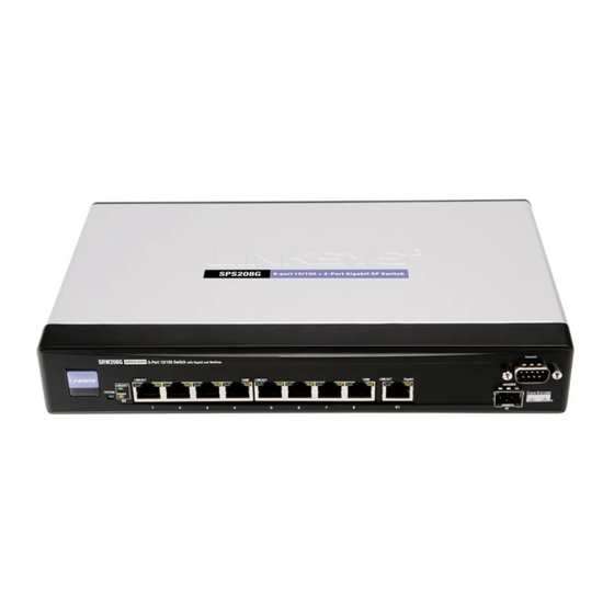
- Page 1 USER GUIDE Cisco Small Business Pro SPS208G/SPS224G4/SPS2024 Ethernet Switches...
- Page 2 © 2008 Cisco Systems, Inc. All rights reserved. OL-18486-01...
-
Page 3: Table Of Contents
L2 DHCP Relay Operation DHCP Relay in Practice - Examples Time Chapter 3: Port Management Port Settings Port Configuration Link Aggregation Link Aggregation Detail LACP Chapter 4: VLAN Management Create VLAN VLAN Port Settings SPS208G/SPS224G4/SPS2024 Service Provider Switches User Guide... - Page 4 View History Table RMON Alarms RMON Events Port Utilization 802.1x Statistics GVRP Statistics Resetting GVRP Statistics Counters CPU Utilization Interface Statistics Resetting Interface Statistics Counters Chapter 6: ACL IP Based ACL MAC Based ACL SPS208G/SPS224G4/SPS2024 Service Provider Switches User Guide...
- Page 5 DHCP Database ARP Inspection ARP Trusted Interfaces ARP Inspection List ARP VLANs IP Source Guard IP Source Guard Database Chapter 9: QoS QoS Modes Service Types Configuring QoS CoS Settings Queue Settings DSCP Settings Bandwidth SPS208G/SPS224G4/SPS2024 Service Provider Switches User Guide...
- Page 6 MSTP Instance Settings VLAN Instance Configuration MSTP Interface Settings Chapter 11: Multicast IGMP Snooping Bridge Multicast Bridge Multicast Forward All Chapter 12: SNMP Global Parameters Views Group Profile Group Membership Communities Notification Filter Notification Recipient SPS208G/SPS224G4/SPS2024 Service Provider Switches User Guide...
- Page 7 Chapter 14: Logout Logout Appendix A: Where to Go From Here Product Resources Related Documentation Appendix B: Additional Information Regulatory Compliance and Safety Information Warranty End User License Agreement (EULA) Appendix C: Support Contacts SPS208G/SPS224G4/SPS2024 Service Provider Switches User Guide...
-
Page 8: Chapter 1: Getting Started
IP address by an administrator. To open the User Interface: Open a web browser. STEP 1 Type the device’s IP address in the address bar and press Enter. The STEP 2 Authentication Page opens. SPS208G/SPS224G4/SPS2024 Service Provider Switches User Guide... - Page 9 Passwords are both case sensitive and alpha-numeric. Summary Page Click OK. The opens, and contains a graphical illustration of the STEP 4 SPS device’s front panel. Figure 2 Summary Page - SPS 208G SPS208G/SPS224G4/SPS2024 Service Provider Switches User Guide...
-
Page 10: Understanding The Interface
Clicking Save Settings saves the active settings on the 4. Configuration current Table Area. Clicking Cancel Changes deletes any Commands changes since the last time the configuration was changed. The Help Area displays help about the displayed feature. 5. Help Area SPS208G/SPS224G4/SPS2024 Service Provider Switches User Guide... -
Page 11: Using The Device Command Buttons
The following table describes the Web Management application’s most common buttons: Table 2 Device Command Buttons Button Description Button Name Save Settings Saves changes to the device’s running configuration. Detail Opens selected entry’s configuration page. Opens an Add page. SPS208G/SPS224G4/SPS2024 Service Provider Switches User Guide... - Page 12 Clear Counters Clears statistic counters Refresh Now Refresh the displayed statistics. Cancel Cancels the configuration changes. Show All Opens a list showing all the items through which you can scroll. SPS208G/SPS224G4/SPS2024 Service Provider Switches User Guide...
-
Page 13: Using Screen And Table Options
Fields which are user-defined can contain between 1 -159 characters, unless otherwise noted on the Web Management application page. All letters or characters can be used, except the following: • • • • • • < • > SPS208G/SPS224G4/SPS2024 Service Provider Switches User Guide... -
Page 14: Modifying Device Information
Management application pages, by selecting an existing entry in the page’s table and clicking the Delete button. Open the Web Management application page. STEP 1 Select a table entry. STEP 2 Click Delete. The entry configuration is deleted, and the device is updated. STEP 3 SPS208G/SPS224G4/SPS2024 Service Provider Switches User Guide... -
Page 15: Resetting The Device
Reboot Screen Click Admin > Reboot. The opens. STEP 1 Figure 4 Reboot Screen Reboot Screen contains the following button: Reboot — Resets the device. Click Reboot to restart and reset the device. STEP 2 SPS208G/SPS224G4/SPS2024 Service Provider Switches User Guide... -
Page 16: Logging Out Of The Device
The Logout command enables network administrators to log out of the device management application in an orderly manner. To log out of the device management application: Logout Screen Click Logout. The opens. STEP 1 Figure 5 Logout Screen Logout Screen notifies whether logout was successful. SPS208G/SPS224G4/SPS2024 Service Provider Switches User Guide... -
Page 17: Chapter 2: Setup
Setup The Setup configuration options are as follows: • Summary • Zoom • Network Settings • DHCP Relay • Time • Stack Management SPS208G/SPS224G4/SPS2024 Service Provider Switches User Guide... -
Page 18: Summary
Network page. • IP Address — Displays the device configuration IP address. • Subnet Mask — Displays the currently configured IP subnet mask. • DNS Server — Displays the DNS server’s IP address. SPS208G/SPS224G4/SPS2024 Service Provider Switches User Guide... - Page 19 The system time is displayed in the following format: Days, Hours, Minutes and Seconds. For example: 41 days, 2 hours, 22 minutes and 15 seconds. • Current Time — Displays the current time and date. SPS208G/SPS224G4/SPS2024 Service Provider Switches User Guide...
-
Page 20: Network Settings
System Contact — Specifies the user-defined system contact person. The field range is 0-160 characters. • System Object ID — Displays the vendor’s authoritative system object identification. • Base MAC Address — Displays the master unit’s base MAC address. SPS208G/SPS224G4/SPS2024 Service Provider Switches User Guide... - Page 21 DHCP renewal procedure (not manual), the device configuration is not overwritten. • IP Address — Indicates the system IP address. • Subnet Mask — Indicates the system IP address mask. • Default Gateway — Indicates the system Default Gateway. SPS208G/SPS224G4/SPS2024 Service Provider Switches User Guide...
-
Page 22: Dhcp Relay
Ensure that DHCP Snooping on all relevant VLANs is enabled and that in the DHCP Snooping configuration, the DHCP server outgoing ports are set to “trusted”. This is an implementation of transparent L2 Relay agent (as described in TR-101 appendix B). SPS208G/SPS224G4/SPS2024 Service Provider Switches User Guide... -
Page 23: L2 Dhcp Relay Quick Start
DHCP Snooping Enabled VLAN Screen (SPS 224G4) In the , add the clients VLAN STEP 2 to the list of enabled VLANs. DHCP Trusted Interface Screen In the , set the DHCP server port as a trusted port. STEP 3 SPS208G/SPS224G4/SPS2024 Service Provider Switches User Guide... -
Page 24: L2 Dhcp Relay Operation
The packet is duplicated and relayed per each DHCP Server. If L2 DHCP relay is enabled; and the DHCP server is on the DHCP request ingress NOTE VLAN, the outgoing relayed packet is sent as a broadcast. SPS208G/SPS224G4/SPS2024 Service Provider Switches User Guide... - Page 25 — Indicates that DHCP Option 82 Insertion is enabled on the device. This option enabled automatically (and grayed) when “Enabled DHP Relay” option is checked. When using Transparent L2 DHCP relay, the user must enable DHCP Snooping manually. SPS208G/SPS224G4/SPS2024 Service Provider Switches User Guide...
-
Page 26: Dhcp Relay In Practice - Examples
DHCP server IP address. The outgoing frame goes on a different VLAN than the one it arrived on. If the server is on a different IP subnet, packets are sent to the default gateway. SPS208G/SPS224G4/SPS2024 Service Provider Switches User Guide... -
Page 27: Time
Bahamas — From April to October, in conjunction with U.S. summer hours. • Belarus — Last weekend of March until the last weekend of October. • Belgium — Last weekend of March until the last weekend of October. SPS208G/SPS224G4/SPS2024 Service Provider Switches User Guide... - Page 28 Jordan — Last weekend of March until the last weekend of October. • Latvia — Last weekend of March until the last weekend of October. • Lebanon — Last weekend of March until the last weekend of October. SPS208G/SPS224G4/SPS2024 Service Provider Switches User Guide...
- Page 29 United Kingdom — Last weekend of March until the last weekend of October. • United States of America — From the second Sunday in March at 02:00 to the first Sunday in November at 02:00. SPS208G/SPS224G4/SPS2024 Service Provider Switches User Guide...
- Page 30 Time Screen Click Setup > Time. The opens. STEP 1 Figure 9 Time Screen Time Screen is divided into four configuration areas: • Set Time • Local Time • Daylight Savings • SNTP Servers SPS208G/SPS224G4/SPS2024 Service Provider Switches User Guide...
- Page 31 Time Zone — Specifies the difference between Greenwich Mean Time (GMT) and local time. For example, the Time Zone Offset for Paris is GMT +1, while the local time in New York is GMT –5. SPS208G/SPS224G4/SPS2024 Service Provider Switches User Guide...
- Page 32 — The device switches to DST at 1:00 am on the last Sunday in March and reverts to standard time at 1:00 am on the last Sunday in October. The European option applies to EU members, and other European countries using the EU standard. SPS208G/SPS224G4/SPS2024 Service Provider Switches User Guide...
- Page 33 — The month of the year in which DST ends. The possible field range is Jan-Dec. Year — The year in which the configured DST ends. Time — The time at which DST starts. The field format is Hour:Minute, for example, 05:30. SPS208G/SPS224G4/SPS2024 Service Provider Switches User Guide...
- Page 34 Secondary Server — Indicates the IP address of the secondary SNTP server. • SNTP Polling Interval — Defines the interval (in seconds) at which the SNTP 60-86400 server is polled. The possible field values are seconds. SPS208G/SPS224G4/SPS2024 Service Provider Switches User Guide...
-
Page 35: Chapter 3: Port Management
Device Port Defaults Administrative Status Configuration SPS2xx FE ports (UNI ports) down shutdown GE ports (NNI ports) no shutdown SPS2024 Ports 12 & 24 (NNI ports) no shutdown All other ports down shutdown SPS208G/SPS224G4/SPS2024 Service Provider Switches User Guide... - Page 36 When selected, all FE ports are defined as protected ports for each VLAN, so that they are isolated from other ports within the same VLAN. The GE ports remain as unprotected ports that function as normal VLAN member ports. SPS208G/SPS224G4/SPS2024 Service Provider Switches User Guide...
- Page 37 The possible field values are: Auto — Use to automatically detect the cable type. SPS208G/SPS224G4/SPS2024 Service Provider Switches User Guide...
- Page 38 • PVE — Indicates that this port is protected by an uplink, so that the forwarding decisions are overwritten by those of the port that protects it. PVE is supported in Layer 2 mode. SPS208G/SPS224G4/SPS2024 Service Provider Switches User Guide...
-
Page 39: Port Configuration
Port Type — Displays the port type. The possible field values are: 100M-copper —Indicates the port has a 100 MB copper port connection. 1000M-copper — Indicates the port has a 1000 MB copper port connection. SPS208G/SPS224G4/SPS2024 Service Provider Switches User Guide... - Page 40 — Indicates that the port is advertising a 10 mbps speed and full Duplex mode setting. 100 Half — Indicates that the port is advertising a 100 mbps speed and half Duplex mode setting. SPS208G/SPS224G4/SPS2024 Service Provider Switches User Guide...
- Page 41 The possible field values are: Auto — Use to automatically detect the cable type. — Use for end stations. MDIX — Use for hubs and switches. SPS208G/SPS224G4/SPS2024 Service Provider Switches User Guide...
-
Page 42: Link Aggregation
LAGs. The device supports up to eight ports per LAG, and eight LAGs per system. To modify LAG settings: Link Aggregation Screen Click Port Management > Link Aggregation. The opens. STEP 1 Figure 13 Link Aggregation Screen SPS208G/SPS224G4/SPS2024 Service Provider Switches User Guide... - Page 43 LAG Mode — Displays the type of link aggregation. The possible field values are: LACP — Link aggregation is set up using LACP. Static — LACP is disabled. Instead, link aggregation is set up. SPS208G/SPS224G4/SPS2024 Service Provider Switches User Guide...
-
Page 44: Link Aggregation Detail
Description — Defines the user-defined LAG name. • LACP Mode — Enables or disables Link Aggregation Control Protocol (LACP). The possible field values are: LACP — LACP is enabled on the LAG. Static — LACP is disabled on the LAG. SPS208G/SPS224G4/SPS2024 Service Provider Switches User Guide... - Page 45 Current Speed — The current speed at which the LAG is operating. • Admin Flow Control — Enables or disables flow control or enables the auto negotiation of flow control on the LAG. • Current Flow Control — The user-designated Flow Control setting. SPS208G/SPS224G4/SPS2024 Service Provider Switches User Guide...
- Page 46 Eth/Gigabit Static — Select the ports to join to the LAG. Define the relevant fields. STEP 2 LAG Aggregation Click Save & Close to save the modifications and close the STEP 3 Screen LAG Aggregation Screen (clicking Save keeps the open). SPS208G/SPS224G4/SPS2024 Service Provider Switches User Guide...
-
Page 47: Lacp
Click Port Management > LACP. The opens. STEP 1 Figure 15 LACP Screen LACP Screen is divided into the following areas for configuring LACP LAGs: • System Priority • Port Priority • LACP Port Table SPS208G/SPS224G4/SPS2024 Service Provider Switches User Guide... - Page 48 Table and the device is updated. LACP Screen For 24-port devices, the displays the ports on multiple screens. To browse to a specific port entry, click the Previous, 1, 2, 3, and Next links above the table. SPS208G/SPS224G4/SPS2024 Service Provider Switches User Guide...
- Page 49 Port Management LACP Figure 16 LACP Port Table SPS208G/SPS224G4/SPS2024 Service Provider Switches User Guide...
-
Page 50: Chapter 4: Vlan Management
VLAN Port Settings • Ports to VLAN • Configuring Q-in-Q • VLAN to Port • GVRP • Multicast TV Membership • Multicast TV Membership • Multicast TV VLAN - IGMP Mapping • CPE VLAN Mapping SPS208G/SPS224G4/SPS2024 Service Provider Switches User Guide... -
Page 51: Create Vlan
Create VLAN Screen Click VLAN Management > Create VLAN. The opens. STEP 1 Figure 17 Create VLAN Screen Create VLAN Screen is divided into the following areas: • Single VLAN • VLAN Range • VLAN Table SPS208G/SPS224G4/SPS2024 Service Provider Switches User Guide... - Page 52 Add Range. The VLAN details appear in the VLAN Table and the device is updated. To delete a VLAN from the device: In the VLAN Table, select the VLAN. STEP 3 Click Delete. The selected VLAN is deleted from the device. STEP 4 SPS208G/SPS224G4/SPS2024 Service Provider Switches User Guide...
-
Page 53: Vlan Port Settings
To browse to a specific interface entry, click the Previous, 1, 2, 3, and Next links above the table. VLAN Port Settings Screen contains the following fields: • Unit No. — Indicates the stacking member being managed. SPS208G/SPS224G4/SPS2024 Service Provider Switches User Guide... - Page 54 Multicast TV VLAN — Indicates if the port is joined to a Multicast TV VLAN, enabling multicast TV transmissions to egress to subscribers through this Access port. The Port Mode must be defined as . Packets passing through the port are untagged. SPS208G/SPS224G4/SPS2024 Service Provider Switches User Guide...
-
Page 55: Ports To Vlan
Ports can have the following configuration options: To assign VLAN membership to ports: Ports To VLAN Screen Click VLAN Management > Ports to VLAN. The opens. STEP 1 Figure 19 Ports To VLAN Screen SPS208G/SPS224G4/SPS2024 Service Provider Switches User Guide... - Page 56 Forbidden — Port cannot be included in the VLAN. • Excluded — Excludes the interface from the VLAN. Click Show All to display a list showing all the items through which you can scroll. STEP 2 SPS208G/SPS224G4/SPS2024 Service Provider Switches User Guide...
- Page 57 VLANs — Indicates the VLAN for which the port membership is configured. Select the relevant configuration options for the interfaces that are included in the STEP 3 VLAN. Click Save Settings to save the VLAN membership configuration. The device is STEP 4 updated. SPS208G/SPS224G4/SPS2024 Service Provider Switches User Guide...
-
Page 58: Configuring Q-In-Q
• Simplified operation, because the service provider does not have to manage the configurations of customer equipment devices. • Increased VLAN scalability, providing up to 4000 private VLANs per subscriber, up to 4000 subscribers. SPS208G/SPS224G4/SPS2024 Service Provider Switches User Guide... -
Page 59: Q-In-Q Implementation
Untagged Tagged (Trunk or General) Customer port forwards single-tagged frame, containing the destination port tag. Untagged Untagged (Customer, Customer port forwards untagged General, or Access) frame. SPS208G/SPS224G4/SPS2024 Service Provider Switches User Guide... - Page 60 Click VLAN Management > Ports to VLAN. STEP 5 In the Ports to VLAN Screen , define all the VLAN Member egress ports that attach STEP 6 VLAN tags to packets passing through them (see Ports to VLAN SPS208G/SPS224G4/SPS2024 Service Provider Switches User Guide...
-
Page 61: Vlan To Port
General — Indicates the port belongs to VLANs, and each VLAN is user- defined as tagged or untagged (full IEEE802. 1 q mode). Access — Indicates a port belongs to a single untagged VLAN. SPS208G/SPS224G4/SPS2024 Service Provider Switches User Guide... - Page 62 LAG cannot be configured to a VLAN, but that same LAG can be configured to a VLAN. Click Show All to display a list showing all the items through which you can scroll. STEP 2 Figure 22 Show All Ports Table SPS208G/SPS224G4/SPS2024 Service Provider Switches User Guide...
- Page 63 Up to 20 VLANs at a single time may be joined to the port. Join VLAN To Port Click Save & Close to save the modifications and close the STEP 6 Screen Join VLAN To Port Screen (clicking Save keeps the open). SPS208G/SPS224G4/SPS2024 Service Provider Switches User Guide...
-
Page 64: Gvrp
GVRP Table: • Configuring GVRP • Enabling/Disabling GVRP on a port /LAG To define GVRP on the device: Click VLAN Management > GVRP. The GVRP Screen opens. STEP 1 Figure 24 GVRP Screen SPS208G/SPS224G4/SPS2024 Service Provider Switches User Guide... - Page 65 GVRP Screen For 8-port devices, the displays the interfaces on multiple screens. To browse to a specific interface entry, click the Previous, 1, 2, and Next links above the table. SPS208G/SPS224G4/SPS2024 Service Provider Switches User Guide...
-
Page 66: Multicast Tv Membership
Multicast Transceiver (source) ports may send Multicast traffic, and must be VLAN members. To display the Multicast TV VLAN member ports and LAGs: Multicast TV Click VLAN Management > Multicast TV Membership. The STEP 1 Membership Screen opens. Figure 25 Multicast TV Membership Screen SPS208G/SPS224G4/SPS2024 Service Provider Switches User Guide... -
Page 67: Multicast Tv Vlan
The port’s Frame Type parameter is set to Admit All, allowing untagged “Port Settings” packets (see The Multicast TV VLAN configuration is defined per port. Multicast TV VLAN has Multicast VLAN Registration been implemented to resemble (MVR), which is the industry standard. SPS208G/SPS224G4/SPS2024 Service Provider Switches User Guide... - Page 68 Select ports from the Customer Ports list and click the left arrow button to move STEP 2 the ports to the Customer Ports Member list. Click Save Settings. Multicast TV VLAN settings are modified, and the device is STEP 3 updated. SPS208G/SPS224G4/SPS2024 Service Provider Switches User Guide...
-
Page 69: Multicast Tv Vlan - Igmp Mapping
Click Add to List. The new VLAN-Multicast group mapping is displayed in the table STEP 3 at the bottom of the screen. Click Save Settings. TV VLAN-Multicast group mapping is defined, and the device STEP 4 is updated. SPS208G/SPS224G4/SPS2024 Service Provider Switches User Guide... -
Page 70: Cpe Vlan Mapping
Click VLAN Management > More > CPE VLAN Mapping. The STEP 1 Screen opens. Figure 28 CPE VLAN Mapping Screen CPE VLAN Mapping Screen is divided into the following areas: • Mapping Parameters • CPE VLAN Mapping Table SPS208G/SPS224G4/SPS2024 Service Provider Switches User Guide... - Page 71 Click Add to List. The mapped VLANs are displayed in the CPE VLAN Mapping STEP 3 table. The CPE VLAN Mapping Table displays the mapped VLANs. Click Save Settings. The device is updated. STEP 4 SPS208G/SPS224G4/SPS2024 Service Provider Switches User Guide...
-
Page 72: Chapter 5: Statistics
Etherlike statistics. The Statistics configuration options are as follows: • RMON Statistics • RMON History • RMON Alarms • RMON Events • Port Utilization • 802. 1 x Statistics • GVRP Statistics • CPU Utilization • Interface Statistics SPS208G/SPS224G4/SPS2024 Service Provider Switches User Guide... -
Page 73: Rmon Statistics
Interface — Indicates the device for which statistics are displayed. The possible field values are: Unit No. — Indicates the stacking member being managed. Port — Defines the specific port for which RMON statistics are displayed. SPS208G/SPS224G4/SPS2024 Service Provider Switches User Guide... - Page 74 64 octets) received on the interface since the device startup or since the counters were cleared. • Oversize Packets — Displays the number of oversized packets (over 1518 octets) received on the interface since the device startup or since the counters were cleared. SPS208G/SPS224G4/SPS2024 Service Provider Switches User Guide...
-
Page 75: Resetting Rmon Statistics Counters
Resetting RMON Statistics Counters RMON Statistics Screen Click Statistics > RMON Statistics. The opens. STEP 1 Click Clear Counters. The RMON statistics counters are reset. STEP 2 To reset the statistics counters, click the Clear Counters button. SPS208G/SPS224G4/SPS2024 Service Provider Switches User Guide... -
Page 76: Rmon History
— Specifies the LAG from which the RMON information was taken. • Sampling Interval — Indicates in seconds the time that samplings are taken from the ports. The field range is 1-3600. The default is 1800 seconds (equal to 30 minutes). SPS208G/SPS224G4/SPS2024 Service Provider Switches User Guide... - Page 77 1-65535. The default value is 50. • Current Number of Samples — Displays the current number of samples taken. RMON History Control Screen In the , click View History Table. STEP 4 SPS208G/SPS224G4/SPS2024 Service Provider Switches User Guide...
-
Page 78: View History Table
Received Bytes (Octets) — Displays the number of octets received on the interface since the device startup or since the counters were cleared. This number includes bad packets and FCS octets, but excludes framing bits. SPS208G/SPS224G4/SPS2024 Service Provider Switches User Guide... - Page 79 Collisions — Displays the number of collisions received on the interface since the device startup or since the counters were cleared. • Utilization — Displays the percentage of the interface utilized. Click Next or Prev to view additional History Table columns. NOTE SPS208G/SPS224G4/SPS2024 Service Provider Switches User Guide...
-
Page 80: Rmon Alarms
• Alarm Entry — Indicates a specific alarm. • Interface — Indicates the interface for which RMON statistics are displayed. The possible field values are: Unit No. — Indicates the stacking member being managed. SPS208G/SPS224G4/SPS2024 Service Provider Switches User Guide... - Page 81 Owner — Displays the device or user that defined the alarm. Define the relevant fields. STEP 2 Click Add To List. The new alarm is defined, and a new alarm entry appears in the STEP 3 Alarm Table. SPS208G/SPS224G4/SPS2024 Service Provider Switches User Guide...
-
Page 82: Rmon Events
To define RMON events: RMON Events Screen Click Statistics > RMON Events. The opens. STEP 1 Figure 35 RMON Events Screen - Add Event Area RMON Events Screen is divided into the following areas: SPS208G/SPS224G4/SPS2024 Service Provider Switches User Guide... - Page 83 Click Add To List. The new event is defined, and a new event entry appears in the STEP 3 Event Table. Figure 36 RMON Event Table RMON Event Table In the , click RMON Events Log. STEP 4 RMON Events Logs Screen The RMON Events Log button displays the SPS208G/SPS224G4/SPS2024 Service Provider Switches User Guide...
- Page 84 Log Time — Displays the time when the log entry was entered. • Description — Displays the log entry description. To return to the RMON Events Screen , click the RMON Events Control button. SPS208G/SPS224G4/SPS2024 Service Provider Switches User Guide...
-
Page 85: Port Utilization
To view all device ports in the same window, click View All Ports. Port Utilization Screen contains the following fields: • Unit No. — Indicates the stacking member being managed. • View All Ports — Displays all ports per unit. SPS208G/SPS224G4/SPS2024 Service Provider Switches User Guide... - Page 86 The graphs show the port utilization percentages for the following factors: • Inbound Utilization — Percentage of port resources used for input traffic. • Outbound Utilization — Percentage of port resources used for output traffic. • Global Overload Line — The port is overloaded. SPS208G/SPS224G4/SPS2024 Service Provider Switches User Guide...
-
Page 87: 802.1X Statistics
Refresh Rate — Defines the amount of time that passes before the EAP statistics are refreshed. The possible field values are: No Refresh — Indicates that the EAP statistics are not refreshed. 15 Sec — Indicates that the EAP statistics are refreshed every 15 seconds. SPS208G/SPS224G4/SPS2024 Service Provider Switches User Guide... - Page 88 Transmit EAPOL/Id — Indicates the number of EAP Req/Id frames transmitted via the port. • Transmit EAPOL/Oth — Indicates the number of EAP Request frames (other than Rq/Id frames) transmitted via the port. Define the Port and Refresh Rate. STEP 2 SPS208G/SPS224G4/SPS2024 Service Provider Switches User Guide...
-
Page 89: Gvrp Statistics
To view the GVRP statistics: GVRP Statistics Screen Click Statistics > GVRP Statistics. The opens. STEP 1 Figure 40 GVRP Statistics Screen GVRP Statistics Screen is divided into two areas, GVRP Statistics Table and GVRP Error Statistics. SPS208G/SPS224G4/SPS2024 Service Provider Switches User Guide... - Page 90 The GVRP Error Statistics Area contains the following fields: • Invalid Protocol ID — Displays the device GVRP Invalid Protocol ID statistics. • Invalid Attribute Type — Displays the device GVRP Invalid Attribute ID statistics. SPS208G/SPS224G4/SPS2024 Service Provider Switches User Guide...
-
Page 91: Resetting Gvrp Statistics Counters
Click Clear Counters. The GVRP statistics counters are cleared. STEP 2 Click Save Settings. The device starts recording GVRP Statistics from zero. STEP 3 To clear the statistics counters, click the Clear Counters button and Save Settings. SPS208G/SPS224G4/SPS2024 Service Provider Switches User Guide... -
Page 92: Cpu Utilization
Refresh Rate — Amount of time that passes before the statistics are refreshed. The possible field values are: No Refresh — Indicates that the CPU utilization statistics are not refreshed. 15 Sec — Indicates that the CPU utilization statistics are refreshed every 15 seconds. SPS208G/SPS224G4/SPS2024 Service Provider Switches User Guide... - Page 93 • Time — Displays a graph x-axis that contains a sliding window of 20 seconds where the CPU load is measured and usage samples are taken. Define the Refresh Rate. STEP 2 SPS208G/SPS224G4/SPS2024 Service Provider Switches User Guide...
-
Page 94: Interface Statistics
• Interface • Ethernet-like Statistics To view Interface statistics: Interface Statistics Screen Click Statistics > More > Interface Statistics. The STEP 1 opens. Figure 42 Interface Statistics Screen - Interface Area SPS208G/SPS224G4/SPS2024 Service Provider Switches User Guide... - Page 95 — Indicates that the Interface statistics are refreshed every 15 seconds. 30 Sec — Indicates that the Interface statistics are refreshed every 30 seconds. 60 Sec — Indicates that the Interface statistics are refreshed every 60 seconds. SPS208G/SPS224G4/SPS2024 Service Provider Switches User Guide...
- Page 96 • Oversize Packets — Displays the number of oversized packet errors on the selected interface. • Internal MAC Receive Errors — Number of internal MAC received errors on the selected interface. SPS208G/SPS224G4/SPS2024 Service Provider Switches User Guide...
-
Page 97: Resetting Interface Statistics Counters
Resetting Interface Statistics Counters Interface Statistics Screen Click Statistics > Interface Statistics. The opens. STEP 1 Click Clear Counters. The Interface statistics counters are cleared. STEP 2 To clear the statistics counters, click the Clear Counters button. SPS208G/SPS224G4/SPS2024 Service Provider Switches User Guide... -
Page 98: Chapter 6: Acl
(ACEs) that are made of the filters that determine traffic classifications. The total number of ACEs that can be defined in all ACLs together is 1024. ACL configuration may take several minutes, depending on the device’s usage of NOTE Ternary Content Addressable Memory (TCAM) resources. SPS208G/SPS224G4/SPS2024 Service Provider Switches User Guide... - Page 99 To display an IP Based ACL configuration, select an ACL Name or enter a new STEP 2 name to create a new ACL. • Action — Indicates the ACL forwarding action. The possible field values are: Permit — Forwards packets which meet the ACL criteria. SPS208G/SPS224G4/SPS2024 Service Provider Switches User Guide...
- Page 100 Protocol. Routing protocol used to construct and maintain routes between source and destination administrative domains. IDRP Inter-Domain Routing Protocol — Matches the packet to the (IDRP). Specifies how routers in different domains within an OSI environment communicate with each other. SPS208G/SPS224G4/SPS2024 Service Provider Switches User Guide...
- Page 101 ACE. Each protocol has a specific protocol number which is unique. The possible field range is 0-255. — Matches the protocol to any protocol. • TCP Flags — Sets the indicated TCP flag that can be triggered. SPS208G/SPS224G4/SPS2024 Service Provider Switches User Guide...
- Page 102 Destination IP Address— Matches the destination port IP address to which packets are addressed to the ACE. Destination Mask — Defines the destination IP address wildcard mask. — Any IP address can be the destination IP address. SPS208G/SPS224G4/SPS2024 Service Provider Switches User Guide...
-
Page 103: Mac Based Acl
MAC- based ACLs to be defined. ACEs can be added only if an ACL is not bound to an interface. ACL configuration may take several minutes, depending on the device’s usage of NOTE Ternary Content Addressable Memory (TCAM) resources. SPS208G/SPS224G4/SPS2024 Service Provider Switches User Guide... - Page 104 — Deletes the selected MAC based ACL. Unchecked — Maintains the MAC based ACLs. To display a MAC Based ACL configuration, select an ACL Name or enter a new STEP 2 name to create a new ACL. SPS208G/SPS224G4/SPS2024 Service Provider Switches User Guide...
- Page 105 — Any MAC address can be the destination MAC address. • VLAN ID — Matches the packet’s VLAN ID to the ACE. The possible field values are 1 to 4095. • Ethertype — Indicates the Ethertype packet by which the packets are filtered. SPS208G/SPS224G4/SPS2024 Service Provider Switches User Guide...
- Page 106 In the MAC Based ACL Table, select the ACL entry to delete. STEP 2 Click Delete. The ACL entry is removed from the MAC Based ACL Table and STEP 3 deleted from the device. SPS208G/SPS224G4/SPS2024 Service Provider Switches User Guide...
-
Page 107: Chapter 7: Network Security
Network Security The Network Security configuration options are as follows: • RADIUS • TACACS+ • ACL Binding • 802. 1 x Settings • Port Authentication • Port Security • Management Access List • Storm Control SPS208G/SPS224G4/SPS2024 Service Provider Switches User Guide... -
Page 108: Radius
• RADIUS Accounting — The authentication method used for RADIUS session accounting. Possible field values are: None — No authentication is used to initiate accounting. Login — Login authentication is used to initiate accounting. SPS208G/SPS224G4/SPS2024 Service Provider Switches User Guide... - Page 109 802. 1 X port authentication. • Authentication Port — Identifies the authentication port. The authentication port is used to verify the RADIUS server authentication. The authenticated port default is 1812. SPS208G/SPS224G4/SPS2024 Service Provider Switches User Guide...
- Page 110 STEP 2 Click Delete. The RADIUS server configuration is removed from the RADIUS Table. STEP 3 Click Save Settings. The device is updated and the RADIUS server configuration is STEP 4 deleted from the device. SPS208G/SPS224G4/SPS2024 Service Provider Switches User Guide...
-
Page 111: Tacacs
TACACS+ servers. If default values are not defined, the system defaults are applied to the new TACACS+ server. To define TACACS+ server authentication settings: TACACS+ Screen Click Network Security > TACACS+. The opens. STEP 1 Figure 48 TACACS+ Screen SPS208G/SPS224G4/SPS2024 Service Provider Switches User Guide... - Page 112 Click Add To List. The TACACS+ server configuration is defined, and it is listed in STEP 3 TACACS+ Screen the TACACS+ Table at the bottom of the Click Save Settings. The device is updated with the TACACS+ server STEP 4 configuration. SPS208G/SPS224G4/SPS2024 Service Provider Switches User Guide...
- Page 113 STEP 2 Click Delete. The TACACS+ server configuration is removed from the TACACS+ STEP 3 Table. Click Save Settings. The device is updated and the TACACS+ server configuration STEP 4 is deleted from the device. SPS208G/SPS224G4/SPS2024 Service Provider Switches User Guide...
-
Page 114: Acl Binding
ACL Binding Screen contains the following fields: • Unit No. — Displays the stacking member for which the ACLs are defined. • Interface — Indicates the port or LAG to which the associated ACL is bound. SPS208G/SPS224G4/SPS2024 Service Provider Switches User Guide... - Page 115 STEP 1 In the table, select the ACL Binding entry to delete. STEP 2 Click Delete. The ACL Binding configuration is removed from the ACL Binding STEP 3 Table and deleted from the device. SPS208G/SPS224G4/SPS2024 Service Provider Switches User Guide...
-
Page 116: 802.1X Settings
Enable 802. 1 x — Enables or disables 802. 1 x on the device. • Port — Indicates the interface to configure the 802. 1 x settings. Unit No. — Indicates the stacking member being managed. Port — Indicates interface to configure. SPS208G/SPS224G4/SPS2024 Service Provider Switches User Guide... - Page 117 VLANs to deny network access via port-based authentication, but grant Internet access to unauthorized users.The possible field values are: Checked — Indicates that an unauthorized user can use the Guest VLAN. Disabled — Indicates that an unauthorized user cannot use the Guest VLAN. SPS208G/SPS224G4/SPS2024 Service Provider Switches User Guide...
- Page 118 The Setting Timer button opens the to configure ports for 802. 1 x functionality. Setting Timer Screen contains the following fields: • Unit No. — Indicates the stacking member being managed. • Port — Indicates the interface. SPS208G/SPS224G4/SPS2024 Service Provider Switches User Guide...
- Page 119 Click Save & Close to save the modifications and close the STEP 5 Setting Timer Screen (clicking Save keeps the open). The defined configuration 802. 1 x Settings Screen appears in the 802. 1 x Table near the bottom of the SPS208G/SPS224G4/SPS2024 Service Provider Switches User Guide...
- Page 120 The displays the 802. 1 x authentication settings for every interface. Click the Base Table link to display only the Status Port Control and Enable Periodic Reauthentication parameters for the interfaces. Click the More Details link to display all parameters for the interlaces. Figure 53 802.1x Table SPS208G/SPS224G4/SPS2024 Service Provider Switches User Guide...
-
Page 121: Port Authentication
To define the port authorization: Port Authentication Screen Click Network Security > Port Authentication. The STEP 1 opens. Figure 54 Port Authentication Screen Port Authentication Screen is divided into two areas: • Port Parameters • Port Table SPS208G/SPS224G4/SPS2024 Service Provider Switches User Guide... - Page 122 Discard — Discards the packets. Forward — Forwards the packet. Shutdown — Discards the packets and shuts down the port. The port remains shut down until reactivated, or until the device is reset. SPS208G/SPS224G4/SPS2024 Service Provider Switches User Guide...
- Page 123 — Indicates that the port control is Auto and Multiple Hosts mode is enabled. One client has been authenticated. Multiple Sessions — Indicates that the port control is Auto and Multiple Sessions mode is enabled. At least one client has been authenticated. SPS208G/SPS224G4/SPS2024 Service Provider Switches User Guide...
-
Page 124: Port Security
Disabled ports are activated from the Port Management > Port Configuration Screen (click the Detail button). Port Security can be enabled only on ports in Multiple User or Multiple Session modes (see Port Authentication SPS208G/SPS224G4/SPS2024 Service Provider Switches User Guide... - Page 125 • Interface — Indicates the port or LAG to configure the Port Security. Unit No. — Indicates the stacking member being managed. Port — Indicates port to configure. LAG — Indicates LAG to configure. SPS208G/SPS224G4/SPS2024 Service Provider Switches User Guide...
- Page 126 — Forwards packets from an unknown source without learning the MAC address. Shutdown — Discards packets from any unlearned source and shuts down the port. The port remains shut down until reactivated, or until the device is reset. SPS208G/SPS224G4/SPS2024 Service Provider Switches User Guide...
- Page 127 For 24-port devices, the Port Security Table displays the interface on multiple screens. To browse to a specific interface entry, click the Previous, 1, 2, 3, and Next links above the table. The Port Security Table displays the security parameters of the ports. SPS208G/SPS224G4/SPS2024 Service Provider Switches User Guide...
-
Page 128: Management Access List
A wild card mask of 255.255.255.255 indicates that no bit is important. A wildcard of 0.0.0.0 indicates that all the bits are important. For example, if the source IP SPS208G/SPS224G4/SPS2024 Service Provider Switches User Guide... -
Page 129: Storm Control
A Broadcast Storm is a result of an excessive amount of Broadcast messages simultaneously transmitted across a network by a single port. Forwarded message responses are heaped onto the network, straining network resources or causing the network to time out. SPS208G/SPS224G4/SPS2024 Service Provider Switches User Guide... - Page 130 Storm Control Screen (SPS 224G4) provides fields for configuring packet Storm Control. Storm Control Screen (SPS Click Network Security > More > Storm Control. The STEP 1 224G4) opens. Figure 57 Storm Control Screen (SPS 224G4) SPS208G/SPS224G4/SPS2024 Service Provider Switches User Guide...
- Page 131 Unicast packets are forwarded. This rate affects all ports that forward unknown Unicast packets at a single time. The ranges are 3500Kbps – 100Mbps for FE ports (applicable to SPS 208 and SPS 224G4 only). SPS208G/SPS224G4/SPS2024 Service Provider Switches User Guide...
- Page 132 To browse to a specific interface entry, click the Previous, 1, 2, 3, and Next links above the table. The Storm Control Table displays the Storm Control configuration configurations for all device interfaces. SPS208G/SPS224G4/SPS2024 Service Provider Switches User Guide...
-
Page 133: Chapter 8: Security Suite
Trusted interfaces receive packets only from within the network or the network firewall. The DHCP Snooping Table contains the untrusted interfaces’ MAC address, IP address, Lease Time, VLAN ID, and interface information. SPS208G/SPS224G4/SPS2024 Service Provider Switches User Guide... - Page 134 DHCP Option 82 data. The possible field values are: Checked — If DHCP Option 82 with data insertion is enabled, the DHCP relay agent or DHCP Snooping switch can insert information into the DHCP DISCOVER message. he Relay agent information option SPS208G/SPS224G4/SPS2024 Service Provider Switches User Guide...
- Page 135 DHCP. IP source guard can be enabled only on DHCP snooping untrusted interface. Unchecked — Disables IP Source Guard on the device. This is the default value. • Check Availability — TBD Retry — TBD Frequency — TBD Never— TBD SPS208G/SPS224G4/SPS2024 Service Provider Switches User Guide...
-
Page 136: Dhcp Vlans
To enable DHCP Snooping on VLANs: DHCP Snooping Enabled VLAN Screen Click Security Suite > DHCP VLANs. The STEP 1 (SPS 224G4) opens. Figure 60 DHCP Snooping Enabled VLAN Screen (SPS 224G4) SPS208G/SPS224G4/SPS2024 Service Provider Switches User Guide... - Page 137 In the Enabled VLANs Table, select the VLAN. STEP 1 Click Delete. The selected VLAN is deleted from the device. STEP 2 The Enabled VLANs Table contains a list of VLANs on which DHCP snooping is enabled. SPS208G/SPS224G4/SPS2024 Service Provider Switches User Guide...
-
Page 138: Dhcp Trusted Interfaces
For 24-port devices, the Trusted Interfaces Table displays the interfaces on multiple screens. To browse to a specific interface entry, click the Previous, 1, 2, 3, and Next links above the table. SPS208G/SPS224G4/SPS2024 Service Provider Switches User Guide... - Page 139 — Indicates that DHCP Snooping Trust mode is disabled on the interface. Enable or disable the Trust Status for the relevant interfaces. STEP 2 Click Save Settings. The Trusted Interfaces are defined, and the device is STEP 3 updated. SPS208G/SPS224G4/SPS2024 Service Provider Switches User Guide...
-
Page 140: Dhcp Database
SNTP Server. The DHCP Snooping Database is stored in the device’s switch memory. To query or add IP addresses: DHCP Database Screen Click Security Suite > DHCP Database. The opens. STEP 1 Figure 62 DHCP Database Screen SPS208G/SPS224G4/SPS2024 Service Provider Switches User Guide... - Page 141 DHCP Snooping entry never expires. Click Query. The results appear in the Query Results table. STEP 3 To browse to a specific DHCP Snooping entry, click the First, Previous, 1, 2, Next, and Last links above the table. SPS208G/SPS224G4/SPS2024 Service Provider Switches User Guide...
-
Page 142: Arp Inspection
ARP inspection is performed only on untrusted interfaces. ARP Inspection Screen provides parameters or enabling and setting global ARP Inspection parameters, as well as defining ARP Inspection Log parameters. SPS208G/SPS224G4/SPS2024 Service Provider Switches User Guide... - Page 143 — Indicates that ARP SYSLOG messages are generated. The interval between successive Syslog messages is the number of seconds entered into the (Sec) field. The range is 0-86400 seconds. The default value is 5. SPS208G/SPS224G4/SPS2024 Service Provider Switches User Guide...
-
Page 144: Arp Trusted Interfaces
Figure 64 ARP Trusted Interfaces Screen For 8-port devices, the Trusted Interfaces Table displays the interfaces on multiple screens. To browse to a specific interface entry, click the Previous, 1, 2, and Next links above the table. SPS208G/SPS224G4/SPS2024 Service Provider Switches User Guide... - Page 145 ARP requests/replies sent to/from the interface. This is the default value. Enable or disable the Trust Status for the relevant interfaces. STEP 2 Click Save Settings. The Trusted Interfaces are defined, and the device is STEP 3 updated. SPS208G/SPS224G4/SPS2024 Service Provider Switches User Guide...
-
Page 146: Arp Inspection List
• List Name — Select from a list of user-defined ARP Inspection Binding Lists. • New List Name — Defines a new ARP Inspection Binding List. List names can contain up to 32 characters. SPS208G/SPS224G4/SPS2024 Service Provider Switches User Guide... - Page 147 STEP 2 Click Save Settings. The ARP Inspection Binding configuration is modified, and the STEP 3 device is updated. The ARP Inspection List Table contains a list of ARP Inspection Binding Lists on the device. SPS208G/SPS224G4/SPS2024 Service Provider Switches User Guide...
-
Page 148: Arp Vlans
IP address-VLAN match. If the entry exists in the DHCP Snooping database, the packet passes through the interface. • If the packet’s IP address is not listed in the ARP Inspection List or the DHCP Snooping database, the device rejects the packet. SPS208G/SPS224G4/SPS2024 Service Provider Switches User Guide... - Page 149 List Name — Assign a static ARP Inspection List to the VLAN. These lists ARP Inspection List Screen. are defined in the To add a bound ARP VLAN to the List To VLAN table, define the VLAN ID and the STEP 2 List Name. SPS208G/SPS224G4/SPS2024 Service Provider Switches User Guide...
-
Page 150: Ip Source Guard
• IP Source Guard cannot be configured on a routed port. • If IP Source Guard and MAC address filtering is enabled on a port, Port Security cannot be activated on the same port. SPS208G/SPS224G4/SPS2024 Service Provider Switches User Guide... - Page 151 IPv4 traffic — Only IPv4 traffic with a source IP address that is associated with the specific port is permitted. Non IPv4 traffic — All non-IPv4 traffic is permitted. SPS208G/SPS224G4/SPS2024 Service Provider Switches User Guide...
- Page 152 For 24-port devices, the IP Source Guard Interface Table displays the interfaces on multiple screens. To browse to a specific interface entry, click the Previous, 1, 2, 3, and Next links above the table. SPS208G/SPS224G4/SPS2024 Service Provider Switches User Guide...
- Page 153 Enable or disable IP Source Guard on the device. STEP 2 Enable or disable IP Source Guard on specific interfaces. STEP 3 Click Save Settings. The IP Source Guard configuration is modified, and the STEP 4 device is updated. SPS208G/SPS224G4/SPS2024 Service Provider Switches User Guide...
-
Page 154: Ip Source Guard Database
To query IP addresses in the IP Source Guard Database: IP Source Guard Click Security Suite > More > IP Source Guard Database. The STEP 1 Database Screen opens. Figure 68 IP Source Guard Database Screen SPS208G/SPS224G4/SPS2024 Service Provider Switches User Guide... - Page 155 — Queries the database by port number. — Queries the VLAN database by LAG number. Click Query. The results appear in the Query Results table. STEP 5 Figure 69 IP Source Guard Database Screen - Query Results SPS208G/SPS224G4/SPS2024 Service Provider Switches User Guide...
- Page 156 VLAN Trusted Port Resource Problem • Status — Displays the current interface status. The possible field values are: Active — Indicates the interface is currently active. Inactive — Indicates the interface is currently inactive. SPS208G/SPS224G4/SPS2024 Service Provider Switches User Guide...
-
Page 157: Chapter 9: Qos
CoS is usually related to the 802. 1 p service that classifies flows according to their Layer 2 priority, as set in the VLAN header. • QoS refers to Layer 2 traffic and above. QoS handles per-flow settings, even within a single traffic class. SPS208G/SPS224G4/SPS2024 Service Provider Switches User Guide... -
Page 158: Qos Modes
VPT, to an output queue. Administrators either apply the default VPT mapping (as defined by the 802. 1 p standard), or may define the mapping according to their own specifications. Mapping is defined on a device-wide basis. SPS208G/SPS224G4/SPS2024 Service Provider Switches User Guide... - Page 159 Class Map — Defining class maps, consisting of one IP ACL and/or one MAC ACL. • Aggregate Policer — Applying aggregate policers to multiple classes in the same policy map. • Interface To Policy — Binding QoS policies to interfaces. SPS208G/SPS224G4/SPS2024 Service Provider Switches User Guide...
-
Page 160: Service Types
Bandwidth control and maximum/minimum thresholds • Scheduling • Traffic shaping on egress interfaces In Advanced QoS mode, policies can be applied directly to an interface. However, a policy and ACL cannot be simultaneously applied to an interface. SPS208G/SPS224G4/SPS2024 Service Provider Switches User Guide... -
Page 161: Configuring Qos
Configuring QoS Configuring QoS The QoS configuration options are as follows: • CoS Settings • Queue Settings • DSCP Settings • Bandwidth • Basic Mode • Advanced Mode SPS208G/SPS224G4/SPS2024 Service Provider Switches User Guide... -
Page 162: Cos Settings
Advanced mode), mapping CoS to queues, and defining the default CoS for each port or LAG. To define CoS Settings: CoS Settings Screen Click QoS > CoS Settings. The opens. STEP 1 Figure 70 CoS Settings Screen SPS208G/SPS224G4/SPS2024 Service Provider Switches User Guide... - Page 163 STEP 2 For 24-port devices, the CoS Default Table displays the interfaces on multiple screens. To browse to a specific interface entry, click the Previous, 1, 2, 3, 4, and Next links above the table. SPS208G/SPS224G4/SPS2024 Service Provider Switches User Guide...
- Page 164 LAG, the LAG settings override the port settings. In the CoS Default Table, define the default CoS levels for the device interfaces. STEP 3 Click Save Settings. The Cos Settings are modified, and the device is updated. STEP 4 SPS208G/SPS224G4/SPS2024 Service Provider Switches User Guide...
-
Page 165: Queue Settings
(WRR). The predetermined weights 8, 2, 4, and 1 are assigned to queues 4, 3, 2 and 1, respectively. WRR and Strict Priority exclude each other and are applied globally to all ports on NOTE the device. SPS208G/SPS224G4/SPS2024 Service Provider Switches User Guide... -
Page 166: Dscp Settings
DSCP tag values to traffic queues. To map DSCP values to queues: Click QoS > DSCP Settings. The DSCP Settings Screen opens. STEP 1 Figure 73 DSCP Settings Screen SPS208G/SPS224G4/SPS2024 Service Provider Switches User Guide... -
Page 167: Bandwidth
Rate Limits and Shaping are defined per interface: • Rate Limit sets the maximum bandwidth allowed on an interface. • Shaping Rate sets the maximum bandwidth allowed on egress interfaces. SPS208G/SPS224G4/SPS2024 Service Provider Switches User Guide... - Page 168 — Indicates the port for which the bandwidth settings are displayed. — Indicates the LAG for which the bandwidth settings are displayed. • Ingress Rate Limit Status — Enables ingress rate limiting on the interface. SPS208G/SPS224G4/SPS2024 Service Provider Switches User Guide...
- Page 169 — Displays the Egress Shaping Rate status for the selected interface. — Displays the Egress traffic shaping rate in CIR for the selected interface. Click Save Settings. The Bandwidth settings are saved and the device is updated. STEP 2 SPS208G/SPS224G4/SPS2024 Service Provider Switches User Guide...
-
Page 170: Basic Mode
Possible values are: — Sets trust mode to CoS on the device. The CoS mapping determines the packet queue. DSCP — Sets trust mode to DSCP on the device. The DSCP mapping determines the packet queue. SPS208G/SPS224G4/SPS2024 Service Provider Switches User Guide... -
Page 171: Advanced Mode
The Advanced Mode Screen also provides access to the following QoS configuration options: • Out of Profile DSCP Assignments • Policy Name • Class Map • Aggregate Policer • Interface To Policy SPS208G/SPS224G4/SPS2024 Service Provider Switches User Guide... - Page 172 Click QoS > Advanced Mode. The opens. STEP 1 Figure 76 Advanced Mode Screen - Policy Settings Advanced Mode Screen is divided into the following areas: • Policy Settings • Policy Table • Interface To Policy SPS208G/SPS224G4/SPS2024 Service Provider Switches User Guide...
- Page 173 — In the New Value box, the possible values are 0-7. – The CoS setting will not affect regular IP traffic. This setting affects NOTE only non-IP traffic, unless the outgoing port is Gigabit port. • Police — Enables Policer functionality. SPS208G/SPS224G4/SPS2024 Service Provider Switches User Guide...
- Page 174 —Forwards packets exceeding the defined CIR value. Define the relevant fields. STEP 2 Click Add To List. The policy profile is defined and is displayed in the Policy Table STEP 3 below the Policy Settings. SPS208G/SPS224G4/SPS2024 Service Provider Switches User Guide...
- Page 175 In the Policy Table below the Policy Settings, click a policy to modify. STEP 2 Define the relevant fields. STEP 3 Click Update. The policy profile is defined and is displayed in the Policy Table. STEP 4 SPS208G/SPS224G4/SPS2024 Service Provider Switches User Guide...
-
Page 176: Out Of Profile Dscp Assignments
Click QoS > Advanced Mode. The opens. STEP 1 Out of In the Policy Settings area, click Out of Profile DSCP Assignments. The STEP 2 Profile DSCP Assignments Screen opens. Figure 78 Out of Profile DSCP Assignments Screen SPS208G/SPS224G4/SPS2024 Service Provider Switches User Guide... -
Page 177: Policy Name
In the Add Alarms area, click Policy Settings. The opens. STEP 2 Figure 79 Policy Name Screen Policy Name Screen is divided into the following areas: • Policy Name Parameter • Policy Name Table SPS208G/SPS224G4/SPS2024 Service Provider Switches User Guide... -
Page 178: Class Map
Class Map Table very important. To add class maps: Advanced Mode Screen Click QoS > Advanced Mode. The opens. STEP 1 New Class Map Screen In the Add Alarms area, click Class Map Settings. The STEP 2 opens. SPS208G/SPS224G4/SPS2024 Service Provider Switches User Guide... - Page 179 Match — Criteria used to match IP addresses and /or MAC addresses with an ACL’s address.The possible field values are: — Both the MAC-based and the IP-based ACL must match a packet. Or — Either the MAC-based or the IP-based ACL must match a packet. SPS208G/SPS224G4/SPS2024 Service Provider Switches User Guide...
-
Page 180: Aggregate Policer
To define aggregate policers: Advanced Mode Screen Click QoS > Advanced Mode. The opens. STEP 1 New Aggregate In the Add Alarms area, click Aggregate Policer Settings. The STEP 2 Policer Screen opens. SPS208G/SPS224G4/SPS2024 Service Provider Switches User Guide... - Page 181 — Drops packets exceeding the defined CIR value. Remark DSCP —Remarks packet’s DSCP values exceeding the defined CIR value. None — Forwards packets exceeding the defined CIR value. Define the relevant fields. STEP 3 SPS208G/SPS224G4/SPS2024 Service Provider Switches User Guide...
-
Page 182: Interface To Policy
QoS policies which are bound to specific interfaces. Advanced Mode Screen Click QoS > Advanced Mode. The opens. STEP 1 Interface To In the Interface To Policy area, click View Interface To Policy. The STEP 2 Policy Screen opens. SPS208G/SPS224G4/SPS2024 Service Provider Switches User Guide... - Page 183 Policy Name — Defines a Policy bound to the interface. Bind policies to relevant interfaces. STEP 3 Click Save Settings. The Interface To Policy settings are saved and the device is STEP 4 updated. SPS208G/SPS224G4/SPS2024 Service Provider Switches User Guide...
-
Page 184: Chapter 10: Spanning Tree
MST regions act as a single bridge. The Spanning Tree configuration options are as follows: • STP Status • Global STP • STP Port Settings • RSTP Port Settings • MSTP Properties • MSTP Instance Settings • MSTP Interface Settings SPS208G/SPS224G4/SPS2024 Service Provider Switches User Guide... -
Page 185: Stp Status
Spanning Tree Mode — Indicates the STP mode that is enabled on the device. • Bridge ID — Identifies the bridge priority and MAC address. • Designated Root — Identifies the bridge priority and MAC address of the root bridge. SPS208G/SPS224G4/SPS2024 Service Provider Switches User Guide... - Page 186 The time is displayed in a day hour minute second format, for example, 2 days 5 hours 10 minutes and 4 seconds: SPS208G/SPS224G4/SPS2024 Service Provider Switches User Guide...
-
Page 187: Global Stp
• Spanning Tree Mode — Indicates the STP mode that is enabled on the device. The possible field values are: Classic STP — Enables Classic STP on the device. This is the default value. SPS208G/SPS224G4/SPS2024 Service Provider Switches User Guide... - Page 188 Hello Time — Specifies the device Hello Time. The Hello Time indicates the amount of time in seconds a root bridge waits between configuration messages. The range is 1 to 10 seconds. The default is 2 seconds. SPS208G/SPS224G4/SPS2024 Service Provider Switches User Guide...
- Page 189 The range is 4 to 30 seconds. The default is 15 seconds. Define the relevant fields. STEP 2 Click Save Settings. The device STP configuration is saved and the device is STEP 3 updated. SPS208G/SPS224G4/SPS2024 Service Provider Switches User Guide...
-
Page 190: Stp Port Settings
Network administrators can assign STP settings to specific interfaces using the STP Port Settings Screen To define interface STP configurations: STP Port Settings Screen Click Spanning Tree > STP Port Settings. The opens. STEP 1 Figure 85 STP Port Settings Screen SPS208G/SPS224G4/SPS2024 Service Provider Switches User Guide... - Page 191 — Indicates that the port is currently blocked and cannot forward traffic or learn MAC addresses. Listening — Indicates that the port is in Listening mode. The port cannot forward traffic nor can it learn MAC addresses. SPS208G/SPS224G4/SPS2024 Service Provider Switches User Guide...
- Page 192 STEP 2 Click Update. The interface STP configuration is defined and is displayed in the STEP 3 STP Port Table. Click Save Settings. The STP configuration is saved and the device is updated. STEP 4 SPS208G/SPS224G4/SPS2024 Service Provider Switches User Guide...
- Page 193 — Provides the lowest cost path to forward packets to the root switch. Designated — The port or LAG through which the designated switch is attached to the LAN. Alternate — Provides an alternate path to the root switch from the root interface. SPS208G/SPS224G4/SPS2024 Service Provider Switches User Guide...
- Page 194 Spanning Tree leaves. Backup ports occur only when two ports are connected in a loop by a point-to-point link, or when a LAN has two or more connections connected to a shared segment. Disabled — The port is not participating in the Spanning Tree. SPS208G/SPS224G4/SPS2024 Service Provider Switches User Guide...
-
Page 195: Rstp Port Settings
Click Spanning Tree > RSTP Port Settings. The opens. STEP 1 Figure 87 RSTP Port Settings Screen RSTP Port Settings Screen is divided into two areas: • RSTP Port Parameters • RSTP Port Table SPS208G/SPS224G4/SPS2024 Service Provider Switches User Guide... - Page 196 The possible field values are: Enable — Fast Link is enabled. Disable — Fast Link is disabled. Auto — Fast Link mode is enabled a few seconds after the interface becomes active. SPS208G/SPS224G4/SPS2024 Service Provider Switches User Guide...
- Page 197 Point-to-Point Oper Status — Indicates the Point-to-Point operating state. • Activate Activate Protocol Migration Test — Click the button to run a Protocol Migration Test. The test identifies the STP mode of the interface connected to the selected interface. SPS208G/SPS224G4/SPS2024 Service Provider Switches User Guide...
- Page 198 STEP 3 Click Update. The interface RSTP configuration is defined and is displayed in the STEP 4 RSTP Port Table. Click Save Settings. The RSTP configuration is saved and the device is updated. STEP 5 SPS208G/SPS224G4/SPS2024 Service Provider Switches User Guide...
-
Page 199: Mstp Properties
Region Name — Provides a user-defined STP region name. • Revision — Defines unsigned 16-bit number that identifies the revision of the current MSTP configuration. The revision number is required as part of the MSTP configuration. The possible field range 0-65535. SPS208G/SPS224G4/SPS2024 Service Provider Switches User Guide... - Page 200 IST Master — Identifies the region’s master. The IST Master is the specified instance root. Define the relevant fields. STEP 2 Click Save Settings. The device MSTP configuration is saved and the device is STEP 3 updated. SPS208G/SPS224G4/SPS2024 Service Provider Switches User Guide...
-
Page 201: Mstp Instance Settings
Screen, in which administrators can map VLANs to MSTP Instances. See VLAN Instance Configuration following this section. See VLAN Instance Configuration. • Instance ID — Specifies the instance being defined. The possible values are 1-7. SPS208G/SPS224G4/SPS2024 Service Provider Switches User Guide... -
Page 202: Vlan Instance Configuration
To map VLANs to MSTP Instance IDs: VLAN Instance Configuration Click Spanning Tree > MSTP Instance Settings. The STEP 1 Screen opens. VLAN Instance Configuration Screen Click VLAN Instance Configuration. The STEP 2 opens. SPS208G/SPS224G4/SPS2024 Service Provider Switches User Guide... - Page 203 The possible field range is 0-7. Click Save & Close to save the modified Instance-to-VLAN mapping and close the STEP 3 VLAN Instance Configuration Screen VLAN Instance (clicking Save keeps the Configuration Screen open). The device is updated. SPS208G/SPS224G4/SPS2024 Service Provider Switches User Guide...
-
Page 204: Mstp Interface Settings
Click Spanning Tree > MSTP Interface Settings. The STEP 1 Screen opens. Figure 92 MSTP Interface Settings Screen MSTP Interface Settings Screen is divided into two areas: • MSTP Interface Parameters • MSTP Interface Table SPS208G/SPS224G4/SPS2024 Service Provider Switches User Guide... - Page 205 MST bridges to LAN in an outlying region. If the port is a boundary port, it also indicates whether the device on the other side of the link is working in RSTP or STP mode SPS208G/SPS224G4/SPS2024 Service Provider Switches User Guide...
- Page 206 LAN to the root. • Designated Cost — DIsplays the cost of the designated port participating in the STP topology. Ports with a lower cost are less likely to be blocked if STP detects loops. SPS208G/SPS224G4/SPS2024 Service Provider Switches User Guide...
- Page 207 For 24-port devices, the MSTP Interface Table displays the interfaces on multiple screens. To browse to a specific interface entry, click the Previous, 1, 2, 3, and Next links above the table. SPS208G/SPS224G4/SPS2024 Service Provider Switches User Guide...
-
Page 208: Chapter 11: Multicast
CPU. The CPU analyzes the incoming packets and determines: • Which ports want to join which Multicast groups. • Which ports have Multicast routers generating IGMP queries. • Which routing protocols are forwarding packets and Multicast traffic. SPS208G/SPS224G4/SPS2024 Service Provider Switches User Guide... - Page 209 IGMP Snooping can be enabled only if Bridge Multicast Filtering is enabled. The possible field values are: Checked — Enables IGMP Snooping on the device. Unchecked — Disables IGMP Snooping on the device. SPS208G/SPS224G4/SPS2024 Service Provider Switches User Guide...
- Page 210 Multicast device to stop sending traffic The Leave Timeout value is either user-defined, or an Immediate Leave value. The possible range is 0-2,147,483,647 seconds. The default timeout is 10 seconds. Select the VLAN ID. STEP 2 Define the relevant fields. STEP 3 SPS208G/SPS224G4/SPS2024 Service Provider Switches User Guide...
- Page 211 Click Save Settings. The IGMP Snooping configuration is saved and the device is STEP 5 updated. The VLAN IGMP Table displays all of the device’s VLANs’ IGMP Snooping configurations. Figure 95 IGMP Snooping Table SPS208G/SPS224G4/SPS2024 Service Provider Switches User Guide...
-
Page 212: Bridge Multicast
To define Multicast groups: Bridge Multicast Screen Click Multicast > Bridge Multicast. The opens. STEP 1 Figure 96 Bridge Multicast Screen Bridge Multicast Screen is divided into two areas: • Configuring Multicast • Multicast Table SPS208G/SPS224G4/SPS2024 Service Provider Switches User Guide... - Page 213 Ports marked as Forbidden None do not belong to a Multicast group. Click Add to List. The configured Multicast group is displayed in the Multicast STEP 5 Table at the bottom of the screen. SPS208G/SPS224G4/SPS2024 Service Provider Switches User Guide...
- Page 214 The Add to List button adds the configured Multicast group to the table at the bottom of the screen. The Show All button displays all the Multicast addresses on all VLANS in the table at the bottom of the screen. Figure 97 Multicast Table SPS208G/SPS224G4/SPS2024 Service Provider Switches User Guide...
-
Page 215: Bridge Multicast Forward All
Forbidden — Indicates the interface is not included the Multicast group, even if IGMP Snooping designated the interface to join a Multicast group. • None — The interface is not configured for Multicast service. SPS208G/SPS224G4/SPS2024 Service Provider Switches User Guide... - Page 216 Add ports and/or LAGs to the Multicast group by selecting STEP 3 Forbidden None Interfaces marked as do not belong to a Multicast group. Click Save Settings. The Multicast Forwarding configuration is saved and the STEP 4 device is updated. SPS208G/SPS224G4/SPS2024 Service Provider Switches User Guide...
-
Page 217: Chapter 12: Snmp
Key Management — Defines key generation, key updates, and key use. The device supports SNMP notification filters based on Object IDs (OID). OIDs are used by the system to manage device features. SNMP v3 supports the following features: Security Feature Access Control Traps SPS208G/SPS224G4/SPS2024 Service Provider Switches User Guide... -
Page 218: Global Parameters
Local Engine ID — Indicates the local device engine ID. The field value is a hexadecimal string. Each byte in hexadecimal character strings consists of two hexadecimal digits. The Engine ID must be defined before SNMPv3 is SPS208G/SPS224G4/SPS2024 Service Provider Switches User Guide... - Page 219 Unchecked — Disables the device from sending authentication failure notifications. Define the relevant fields. STEP 2 Click Save Settings. The SNMP authentication and notification configuration is STEP 3 saved and the device is updated. SPS208G/SPS224G4/SPS2024 Service Provider Switches User Guide...
-
Page 220: Views
The Views Parameters area contains the following fields: • View Name — Indicates the user-defined views. The default options are as follows: Default — Indicates the default SNMP view for read and read/write views. SPS208G/SPS224G4/SPS2024 Service Provider Switches User Guide... - Page 221 To delete an SNMP view from the device: In the Views Table, select the entry. STEP 1 Click Delete. The selected SNMP view configuration is deleted from the device. STEP 2 SPS208G/SPS224G4/SPS2024 Service Provider Switches User Guide...
-
Page 222: Group Profile
• Group Table The Group Parameters area contains the following fields: • Group Name — Indicates the user-defined group to which access control rules are applied. The field range is up to 30 characters. SPS208G/SPS224G4/SPS2024 Service Provider Switches User Guide... - Page 223 — Defines the default group access rights for administrator. Define the relevant fields. STEP 2 Click Add to List. The group profile is displayed in the Log Table at the bottom of STEP 3 the screen. SPS208G/SPS224G4/SPS2024 Service Provider Switches User Guide...
- Page 224 STEP 3 updated. To delete an SNMP group profile from the device: In the Group Table, select the entry. STEP 1 Click Delete. The selected SNMP group profile is deleted from the device. STEP 2 SPS208G/SPS224G4/SPS2024 Service Provider Switches User Guide...
-
Page 225: Group Membership
To add members to SNMP groups: Group Membership Screen Click SNMP > Group Membership. The opens. STEP 1 Figure 102 SNMP Group Membership Screen Group Membership Screen is divided into two areas: • Group Member Parameters • User Table SPS208G/SPS224G4/SPS2024 Service Provider Switches User Guide... - Page 226 Privacy Key — Defines the Privacy Key (LSB). If only authentication is required, 16 bytes are defined. Each byte in hexadecimal character strings is two hexadecimal digits. Each byte can be separated by a period or colon. Define the relevant fields. STEP 2 SPS208G/SPS224G4/SPS2024 Service Provider Switches User Guide...
- Page 227 To delete an SNMP group member from the device: In the User Table, select the entry. STEP 1 Click Delete. The selected SNMP group member is deleted from the device. STEP 2 SPS208G/SPS224G4/SPS2024 Service Provider Switches User Guide...
-
Page 228: Communities
SNMP communities are defined only for SNMP v1 and SNMP v2c. To define SNMP communities: Communities Screen Click SNMP > Communities. The opens. STEP 1 Figure 103 SNMP Communities Screen Communities Screen contains the following areas: • Communities Parameters • Basic Table SPS208G/SPS224G4/SPS2024 Service Provider Switches User Guide... - Page 229 — Assigns the SNMP community to a specific group. Define the relevant fields. STEP 2 Click Add to List. The new community is displayed in either the Basic Table or STEP 3 Advanced Table at the bottom of the screen. SPS208G/SPS224G4/SPS2024 Service Provider Switches User Guide...
- Page 230 View Name — Displays the view name assigned to the community. The Advanced Table area contains the following fields: • Management Station — Displays the management station IP address for which the SNMP community is defined. SPS208G/SPS224G4/SPS2024 Service Provider Switches User Guide...
- Page 231 To delete an SNMP community from the device: Select the community in the Basic or Advanced Table. STEP 1 Click Delete. The selected SNMP community is deleted from the device. STEP 2 SPS208G/SPS224G4/SPS2024 Service Provider Switches User Guide...
-
Page 232: Notification Filter
To add a notification filter: Notification Filter Screen Click SNMP > Notification Filter. The opens. STEP 1 Figure 105 Notification Filter Screen Notification Filter Screen contains the following areas: • Filter Parameters • Filter Table SPS208G/SPS224G4/SPS2024 Service Provider Switches User Guide... - Page 233 Click Add to List. The new filter is displayed in the Filter Table at the bottom of the STEP 3 screen. The Add to List button adds the filter to the Filter Table at the bottom of the screen. Figure 106 Notification Filter Table SPS208G/SPS224G4/SPS2024 Service Provider Switches User Guide...
- Page 234 STEP 3 is updated. To delete an SNMP notification filter from the device: Select the filter in the Filter Table. STEP 1 Click Delete. The selected filter is deleted from the device. STEP 2 SPS208G/SPS224G4/SPS2024 Service Provider Switches User Guide...
-
Page 235: Notification Recipient
Click SNMP > More > Notification Recipient. The STEP 1 opens. Figure 107 Notification Recipient Screen Notification Recipient Screen contains the following areas: • Notification Recipient Parameters • SNMPv1,2 Notification Recipient Table • SNMPv3 Notification Recipient Table SPS208G/SPS224G4/SPS2024 Service Provider Switches User Guide... - Page 236 The range is 1-300 seconds. The default is 15 seconds. • Retries — Indicates the number of times the device re-sends an inform request. The range is 0-255 times. The default is 3 times. SPS208G/SPS224G4/SPS2024 Service Provider Switches User Guide...
- Page 237 To delete an SNMP notification filter from the device: Select the recipient in either the SNMPv1,2 Table or the SNMPv3 Table. STEP 1 Click Delete. The selected filter is deleted from the device. STEP 2 SPS208G/SPS224G4/SPS2024 Service Provider Switches User Guide...
-
Page 238: Chapter 13: Admin
• Dynamic Address • Logging • Port Mirroring • Cable Test • Saving or Upgrading a Configuration • Firmware Upgrade • Reboot • Factory Default • Server Logs • Memory Logs • Flash Logs SPS208G/SPS224G4/SPS2024 Service Provider Switches User Guide... -
Page 239: User Authentication
User Authentication Screen Click Admin > User Authentication. The opens. STEP 1 Figure 109 User Authentication Screen User Authentication Screen contains the following areas: • User Authentication Parameters • Local Users Edit • Local Users Table SPS208G/SPS224G4/SPS2024 Service Provider Switches User Guide... - Page 240 Password field. Define the relevant fields. STEP 1 Click Add to List. The new user configuration is displayed in the Local Users Table STEP 2 at the bottom of the screen. SPS208G/SPS224G4/SPS2024 Service Provider Switches User Guide...
- Page 241 STEP 1 Click Delete. The selected user is deleted from the Local Users Table. STEP 2 Click Save Settings. The selected user is deleted from the device and the device STEP 3 is updated. SPS208G/SPS224G4/SPS2024 Service Provider Switches User Guide...
-
Page 242: Static Address
To define static MAC addresses to interfaces: Static Address Screen Click Admin > Static Address. The opens. STEP 1 Figure 110 Static Address Screen Static Address Screen contains the following areas: • Static Address Parameters • Static Address Table SPS208G/SPS224G4/SPS2024 Service Provider Switches User Guide... - Page 243 Select the address in the Static Address Table. STEP 1 Define the relevant fields. STEP 2 Click Update. The address entry is updated in the Static Address Table. The STEP 3 device is updated. SPS208G/SPS224G4/SPS2024 Service Provider Switches User Guide...
-
Page 244: Dynamic Address
Dynamic MAC Address table. The Dynamic MAC Address table contains address parameters by which packets are directly forwarded to the ports. The Dynamic Address Table can be sorted by interface, VLAN, and MAC Address. SPS208G/SPS224G4/SPS2024 Service Provider Switches User Guide... - Page 245 Dynamic MAC Address table before it is timed out, if no traffic from the source is detected. The default value is 300 seconds. • Clear Table — If checked, clears the MAC address table. SPS208G/SPS224G4/SPS2024 Service Provider Switches User Guide...
-
Page 246: Logging
Each message severity determines the set of event logging devices that are sent per each event logging. Logging Screen In the , network administrators define the levels of event severity that are recorded to the system event logs. SPS208G/SPS224G4/SPS2024 Service Provider Switches User Guide... - Page 247 — Logging is disabled. • Emergency —The system is not functioning. • Alert — The system needs immediate attention. • Critical — The system is in a critical state. • Error — A system error has occurred. SPS208G/SPS224G4/SPS2024 Service Provider Switches User Guide...
- Page 248 Logging can be performed in Memory and in Flash. Memory Logs are deleted at reboot. Flash Logs are available after reboot. Define the required severity levels. STEP 2 Click Save Settings. The system logging configuration is saved and the device is STEP 3 updated. SPS208G/SPS224G4/SPS2024 Service Provider Switches User Guide...
-
Page 249: Port Mirroring
To enable port mirroring: Port Mirroring Screen Click Admin > Port Mirroring. The opens. STEP 1 Figure 113 Port Mirroring Screen Port Mirroring Screen contains the following areas: • Port Mirroring Parameters • Port Mirroring Table SPS208G/SPS224G4/SPS2024 Service Provider Switches User Guide... - Page 250 Define the relevant fields. STEP 2 Click Update. The port mirroring entry is updated in the Port Mirroring Table. STEP 3 Click Save Settings. The port mirroring configuration is updated in the device. STEP 4 SPS208G/SPS224G4/SPS2024 Service Provider Switches User Guide...
- Page 251 Select the entry in the Static Address Table. STEP 1 Click Delete. The selected port mirroring entry is deleted from the Static Address STEP 2 Table. Click Save Settings. The port mirroring configuration is deleted from the device. STEP 3 SPS208G/SPS224G4/SPS2024 Service Provider Switches User Guide...
-
Page 252: Cable Test
Figure 114 Cable Test Screen For 24-port devices, the Cable Test Screen displays the interfaces on multiple screens. To browse to a specific interface entry, click the Previous, 1, 2, 3, and Next links above the table. SPS208G/SPS224G4/SPS2024 Service Provider Switches User Guide... - Page 253 • Cable Status — Displays the cable status. • Speed — Indicates the speed at which the cable is transmitting packets. • Link Status — Displays the current link status. SPS208G/SPS224G4/SPS2024 Service Provider Switches User Guide...
-
Page 254: Saving Or Upgrading A Configuration
Running Configuration when the system last rebooted or shut down. • Backup configuration — Contains a copy of the system configuration for protection against system shutdown, or for maintenance of a specific operating state. SPS208G/SPS224G4/SPS2024 Service Provider Switches User Guide... - Page 255 File Type field. This is an upgrade procedure. • Backup — Specifies that the source is the Running Configuration on the device and the destination is a configuration file on the TFTP server. This is a backup procedure. SPS208G/SPS224G4/SPS2024 Service Provider Switches User Guide...
- Page 256 Source File Type — Indicates the type of configuration file to copy from the device. The possible value is: Running Config — Contains the parameter definitions currently defined on the device, including any configuration changes made since the SPS208G/SPS224G4/SPS2024 Service Provider Switches User Guide...
- Page 257 Startup Config — Contains the parameter definitions which were valid when the Running Configuration was saved. The Startup Configuration is used when the system restarts or starts after shutdown. SPS208G/SPS224G4/SPS2024 Service Provider Switches User Guide...
- Page 258 Source File — Defines the file name when using the HTTP Server to load the configuration file. Define the auto configuration. STEP 5 Click Save Settings. The defined configuration file modes are saved and the STEP 6 device is updated. SPS208G/SPS224G4/SPS2024 Service Provider Switches User Guide...
-
Page 259: Enabling Dchp Option 67
Enable DHCP load configuration (option 67) — Indicates if DHCP Option 67 is enabled. The possible field values are: Checked — Enables DHCP Option 67 on the device. Unchecked — Disables DHCP Option 67 on the device. SPS208G/SPS224G4/SPS2024 Service Provider Switches User Guide... -
Page 260: Firmware Upgrade
Firmware Upgrade Screen contains the following fields: • via TFTP — Specifies that the upgrade is downloaded from a TFTP Server. • via HTTP — Specifies that the upgrade is downloaded from an HTTP Server. SPS208G/SPS224G4/SPS2024 Service Provider Switches User Guide... - Page 261 All Units — Specifies to upgrade all stackable units, including the Master. If via HTTP is selected, enter the following information: STEP 3 • Source File — Defines the file name to be downloaded when using HTTP. SPS208G/SPS224G4/SPS2024 Service Provider Switches User Guide...
-
Page 262: Reboot
Click Admin > More > Reboot. The opens. STEP 1 Figure 119 Reboot Screen Reboot Screen contains the following button: • Reboot — Resets the device. Click Reboot to restart and reset the device. STEP 2 SPS208G/SPS224G4/SPS2024 Service Provider Switches User Guide... -
Page 263: Factory Default
Restore Default — The device is restored to the factory default configuration after system reset. In Stacking mode, unit no. 1 becomes the Master, and the stacking members are reset. Click Restore Default to restore the device to the factory default configuration. STEP 2 SPS208G/SPS224G4/SPS2024 Service Provider Switches User Guide... -
Page 264: Server Logs
To define remote log servers: Server Logs Screen Click Admin > More > Server Logs. The opens. STEP 1 Figure 121 Server Logs Screen Server Logs Screen contains the following areas: • Log Parameters • Log Table SPS208G/SPS224G4/SPS2024 Service Provider Switches User Guide... - Page 265 Click Add to List. The new Server Log configuration is displayed in the Log Table STEP 3 at the bottom of the screen. The Add to List button adds the Server Log configuration to the Log Table. SPS208G/SPS224G4/SPS2024 Service Provider Switches User Guide...
- Page 266 To delete a Server Log configuration from the device: Select the entry in the Log Table. STEP 1 Click Delete. The selected Server Log configuration is deleted from the device. STEP 2 SPS208G/SPS224G4/SPS2024 Service Provider Switches User Guide...
-
Page 267: Memory Logs
Log Index — Displays the log number. • Log Time — Displays the time at which the log was generated. • Severity — Displays the log severity. • Description — Displays the log message text. SPS208G/SPS224G4/SPS2024 Service Provider Switches User Guide... -
Page 268: Flash Logs
The Flash Log is available after reboot. To view the Flash Log: Click Admin > More > Flash Logs. The Flash Logs Screen opens. STEP 1 Figure 123 Flash Logs Screen SPS208G/SPS224G4/SPS2024 Service Provider Switches User Guide... - Page 269 Log Time — Displays the time at which the log was generated. • Severity — Displays the log severity. • Description — Displays the log message text. To clear the Flash Log, click the Clear Log button. All log entries are cleared. SPS208G/SPS224G4/SPS2024 Service Provider Switches User Guide...
-
Page 270: Chapter 14: Logout
The Logout command enables network administrators to log out of the device management application in an orderly manner. To log out of the device management application: Logout Screen Click Logout. The opens. STEP 1 Figure 124 Logout Screen SPS208G/SPS224G4/SPS2024 Service Provider Switches User Guide... - Page 271 Logout Logout Logout Screen notifies whether logout was successful. SPS208G/SPS224G4/SPS2024 Service Provider Switches User Guide...
-
Page 272: Appendix A: Where To Go From Here
Cisco Partner Central (requires partner registration and login) Cisco Small Medium www.cisco.com/go/smallbiz Business Product Information Related Documentation For additional information about the Ethernet switches, see the SPS208G/ SPS224G4/SPS2024 Ethernet Switches Command Line Interface Reference Guide. SPS208G/SPS224G4/SPS2024 Service Provider Switches User Guide... -
Page 273: Appendix B: Additional Information
Regulatory Compliance and Safety Information for this product is available on Cisco.com at the following location: www.cisco.com/go/smallbiz Warranty Warranty information that applies to this product is available on Cisco.com at the following location: www.cisco.com/go/smallbiz End User License Agreement (EULA) Licensing information that applies to this product is available on Cisco.com at the following location: www.cisco.com/go/smallbiz... -
Page 274: Appendix C: Support Contacts
Support Contacts Support contact information for this product is available on Cisco.com at the following location: www.cisco.com/go/smallbiz SPS208G/SPS224G4/SPS2024 Service Provider Switches User Guide...
Need help?
Do you have a question about the SPS208G and is the answer not in the manual?
Questions and answers