Table of Contents
Advertisement
Quick Links
Advertisement
Table of Contents

Related Manuals for Cisco SRW224G4-K9-NA


Summary of Contents for Cisco SRW224G4-K9-NA
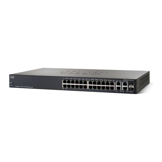
- Page 1 Quick Start Guide Cisco Small Business 300 Series Managed Switches...
-
Page 2: Mounting The Cisco Switch
Welcome Thank you for choosing the Cisco Small Business 300 Series Managed Switch, a Cisco Small Business network communications device. This device is designed to be operational right out of the box as a standard bridge. In the default configuration, it will forward packets between connecting devices after power up. -
Page 3: Rack-Mount Placement
Some switches have a higher temperature rating. The SG300- 10SFP, SG300-52P and SG300-52MP are rated at 113 degrees Fahrenheit (45 degrees Centigrade), and the SG300-28MP, and SF300- 24MP are rated at 122 degrees Fahrenheit (50 degrees Centigrade). Reduced Air Flow—Both side panels must be unobstructed to prevent overheating. -
Page 4: Wall Mounting
The switch should have a minimum of 5 inches (130 mm) of clearance on all sides. Insecure mounting may damage the device or cause injury. ARNING Cisco is not responsible for damages incurred by insecure wall- mounting. 300 Series Managed Switches... -
Page 5: Connecting Network Devices
Cisco strongly recommends using Cat5 or better cable for Gigabit connectivity. When you connect your network devices, do not exceed the maximum cabling distance of 100 meters (328 feet). It can take up to one minute for attached devices or the LAN to be operational after it is connected. -
Page 6: Power Over Ethernet (Poe) Considerations
Power over Ethernet (PoE) Considerations If your switch is one of the PoE models, consider the following table for specific information: 300 Series Switches with Power Over Ethernet Model Power Number of Dedicated to Ports Standard Supporting Supported SF302-08P 62 Watts 802.3af SF302-08MP 124 Watts... - Page 7 Consider the following when connecting switches capable of AUTION supplying PoE: The PoE models of the switches are PSE (Power Sourcing Equipment) that are capable of supplying DC power to attaching PD (Powered Devices). These devices include VoIP phones, IP cameras, and wireless access points. The PoE switches can detect and supply power to pre-standard legacy PoE Powered Devices.
- Page 8 Configuring the Cisco Small Business Managed Switch Before You Begin Verify the managing computer requirements in the product release notes. The switch can be accessed and managed by two different methods; over your IP network using the web-based interface, or by the Command Line Interface (CLI) through the console port.
- Page 9 Enter the default login information: • Username is cisco • Default password is cisco (passwords are case sensitive) If this is the first time that you have logged on with the default Change Password Page username and password, the opens. The rules for constructing a new login and password are displayed on the page.
- Page 10 Enter a user name and password. User names and passwords are both case sensitive and alpha-numeric. The default username is cisco, and the default password is cisco. If this is the first time that you have logged on with the default...
-
Page 11: Troubleshoot Your Connection
Troubleshoot Your Connection If you cannot access your switch from the web-based interface, the switch may not be reachable from your computer. You can test network connections by using ping on a computer running Windows: Open a command window by using Start > Run and enter cmd. At the Command window prompt enter ping and the managed switch IP address. -
Page 12: Front Panel Ports
These ports are also commonly referred to as miniGigaBit Interface Converter (miniGBIC) ports. The term SFP will be used in this guide. • SFP ports are compatible with Cisco modules MGBT1, MGBSX1, MGBLH1, MGBLX1, MGBBX1, MFELX1, MFEFX1, and MFEBX1, as well as other brands of modules. -
Page 13: Front Panel Leds
disabled. Combo ports are indicated by the presence of a bar on the panel that connects them, as shown in the following example: • The LEDs of the corresponding RJ-45 port light to respond to the SFP interface traffic. SG300-10SFP ports 1—8 are dedicated SFP ports. Their LED status and indication are the same as on the RJ-45 ports. -
Page 14: Back Panel
Back Panel The power port and console port are located on the back panel of the managed switch. Power—The Power port is where you will connect the switch to power. Depending on the model of switch you are using, this may be a power cord or a power adaptor. -
Page 15: Where To Go From Here
Cisco Small Business Support www.cisco.com/go/sbsc Center (SBSC) Contacts Cisco Small Business Firmware www.cisco.com/go/smallbizfirmware Downloads Select a link to download firmware for Cisco Small Business Products. No login is required. Product Documentation 300 Series Managed Switches www.cisco.com/go/300switches Click on the Resources Tab Regulatory, Compliance, and www.cisco.com/en/US/docs/switches/lan/... - Page 16 Cisco and the Cisco logo are trademarks or registered trademarks of Cisco and/or its affiliates in the U.S. and other countries. To view a list of Cisco trademarks, go to this URL: www.cisco.com/go/trademarks. Third-party trademarks mentioned are the property of their respective owners.
Need help?
Do you have a question about the SRW224G4-K9-NA and is the answer not in the manual?
Questions and answers