Toshiba B-EX4T2 SERIES Owner's Manual
B-ex4t2 series
Hide thumbs
Also See for B-EX4T2 SERIES:
- Manual (70 pages) ,
- Key operation specification (190 pages) ,
- Printer driver operating manual (105 pages)

Related Manuals for Toshiba B-EX4T2 SERIES


Summary of Contents for Toshiba B-EX4T2 SERIES
- Page 1 TOSHIBA Barcode Printer B-EX4T2 SERIES Owner’s Manual Mode d’emploi Bedienungsanleitung Manual de instrucciones Gebruikershandleiding Manuale Utente Manual do Utilizador...
- Page 2 TOSHIBA Barcode Printer B-EX4T2 SERIES Owner's Manual...
- Page 3 Canada.” (for CANADA only) N258 IP20 Copyright © 2012 < For EU Only > by TOSHIBA TEC CORPORATION TOSHIBA TEC Europe Retail Information Systems S.A. All Rights Reserved 6-78 Minami-cho, Mishima-shi, Shizuoka-ken, JAPAN Rue de la Célidée 33 BE-1080 Brussels...
- Page 4 Waste Recycling information for users: Following information is only for EU-member states: The use of the crossed-out wheeled bin symbol indicates that this product may not be treated as general household waste. By ensuring this product is disposed of correctly you will help prevent potential negative consequences for the environment and human health, which could otherwise be caused by inappropriate waste handling of this product.
- Page 5 For Europe This device was tested and certified by Notified Body. Hereby, Toshiba TEC Corporation declares that this device is in compliance with the essential requirements and other relevant provisions of Directive 1999/5/EC. This equipment uses the radio frequency band which has not been standardised throughout the EU and EFTA countries.
-
Page 6: Safety Summary
Do not attempt to effect repairs or modifications to this equipment. If a fault occurs that cannot be rectified using the procedures described in this manual, turn off the power, unplug the machine, and then contact your authorised TOSHIBA TEC representative for assistance. Meanings of Each Symbol This symbol indicates warning items (including cautions). - Page 7 • Utilise our maintenance services. After purchasing the machine, contact your authorised TOSHIBA TEC representative for assistance once a year to have the inside of the machine cleaned. Dust will build up inside the machines and may cause a fire or a malfunction. Cleaning is particularly effective before humid rainy seasons.
-
Page 8: Table Of Contents
ENGLISH VERSION EO1-33094 TABLE OF CONTENTS Page PRODUCT OVERVIEW ....................... E1- 1 Introduction......................... E1- 1 Features ........................E1- 1 Unpacking........................E1- 1 Accessories ....................... E1- 2 Appearance ........................ E1- 3 1.5.1 Dimensions ....................... E1- 3 1.5.2 Front View......................... E1- 3 1.5.3 Rear View ......................... - Page 9 CAUTION! 1. This manual may not be copied in whole or in part without prior written permission of TOSHIBA TEC. 2. The contents of this manual may be changed without notification.
-
Page 10: Product Overview
1. PRODUCT OVERVIEW ENGLISH VERSION EO1-33094 1.1 Introduction 1. PRODUCT OVERVIEW Thank you for choosing the TOSHIBA B-EX4T2 series bar code 1.1 Introduction printer. This Owner’s Manual contains from general set-up through to how to confirm the printer operation using a test print, and should be read carefully to help gain maximum performance and life from your printer. -
Page 11: Accessories
1. PRODUCT OVERVIEW ENGLISH VERSION EO1-33094 1.4 Accessories When unpacking the printer, please make sure all the following Accessories accessories are supplied with the printer. Power cord Safety precautions Quick installation manual CD-ROM(1pc.) E1- 2... -
Page 12: Appearance
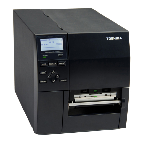
1. PRODUCT OVERVIEW ENGLISH VERSION EO1-33094 1.5 Appearance The names of the parts or units introduced in this section are used 1.5 Appearance in the following chapters. 1.5.1 Dimensions 278 (10.9) 460 (18.1) (12.2) Dimensions in mm (inches) 1.5.2 Front View Top Cover LCD Message Display Supply Window... -
Page 13: Operation Panel
1. PRODUCT OVERVIEW ENGLISH VERSION EO1-33094 1.5 Appearance 1.5.4 Operation Panel ERROR LED ONLINE LED PAUSE FEED RESTART MODE LEFT RIGHT ENTER CANCEL DOWN Please see Section 3 for further information about the Operation Panel. 1.5.5 Interior Ribbon Shaft 1.6 Options Paper Guide R Print Head Block Print Head... -
Page 14: Options
Installing this card provides an RS-232C interface port. Wireless LAN B-EX700-WLAN-QM-R Installing this card provides Wireless LAN interface card communication. NOTE: To purchase the optional kits, please contact the nearest authorised TOSHIBA TEC representative or TOSHIBA TEC Head Quarters. E1- 5... -
Page 15: Printer Setup
2. PRINTER SETUP ENGLISH VERSION EO1-33094 2. PRINTER SETUP 2. PRINTER SETUP This section outlines the procedures to setup your printer prior to its operation. The section includes precautions, loading media and ribbon, connecting cables, setting the operating environment of the printer and performing an online print test. -
Page 16: Installation
• allow fingers or articles of clothing to get caught in any of the moving parts, especially the optional cutter mechanism. For best results, and longer printer life, use only TOSHIBA TEC • recommended media and ribbons. Store the media and ribbons in accordance with their specifications. -
Page 17: Connecting The Power Cord
2. PRINTER SETUP ENGLISH VERSION EO1-33094 2.2 Connecting the Power Cord 2.2 Connecting the 1. Make sure that the printer Power Switch is in the OFF ( ) position. Power Cord Connect the Power Cord to the printer as shown in the figure below. CAUTION! 1. -
Page 18: Loading Supplies
2. PRINTER SETUP ENGLISH VERSION EO1-33094 2.3 Loading Supplies 2.3 Loading Supplies WARNING! 1. Do not touch any moving parts. To reduce the risk of fingers, jewellery, clothing, etc., being drawn into the moving parts, be sure to load the media once the printer has stopped moving completely. -
Page 19: Loading The Media
Position TAG : Tags Lever However, proper position may differ depending on media. For details, refer to your TOSHIBA TEC authorised service 4. Move the Paper guide R to the rightmost position or shift the representative. guide to the horizontal position. - Page 20 2. PRINTER SETUP ENGLISH VERSION EO1-33094 2.3 Loading Supplies 2.3.1 Loading the Media In the case of labels rolled with In the case of labels rolled with (Cont.) the print side facing inside. the print side facing outside. NOTE: Do not over-tighten the Locking Ring of the Supply Holder.
- Page 21 2. PRINTER SETUP ENGLISH VERSION EO1-33094 2.3 Loading Supplies 10. Lower the Print Head Block. 2.3.1 Loading the Media 11. Once the media is loaded it may be necessary to set the Media (Cont.) Sensors used to detect the start position for label or tag. Setting the Feed Gap Sensor position (1) Manually move the Media Sensor so that the Feed Gap Sensor is positioned at the centre of the labels.
- Page 22 2. PRINTER SETUP ENGLISH VERSION EO1-33094 2.3 Loading Supplies 12. Batch mode 2.3.1 Loading the Media In batch mode, the media is continuously printed until the number of (Cont.) labels/tags specified in the issue command has been printed. 13. Loading with peel off module When the optional Strip Module is fitted, the label is automatically removed from the backing paper at the Strip Plate as each label is printed.
- Page 23 2. PRINTER SETUP ENGLISH VERSION EO1-33094 2.3 Loading Supplies 2.3.1 Loading the Media 14. Loading with cutter (Cont.) When the optional Cutter Module is fitted, the media is automatically cut. A disc cutter is available as option. WARNING! Insert the leading edge of the media into the cutter until it comes out the Media Outlet of the Cutter Module.
-
Page 24: Loading The Ribbon
2. PRINTER SETUP ENGLISH VERSION EO1-33094 2.3 Loading Supplies There are two types of media available for printing on: thermal 2.3.2 Loading the Ribbon transfer and direct thermal (which has a chemically treated NOTES: surface). DO NOT LOAD a ribbon when using direct thermal 1. - Page 25 2. PRINTER SETUP ENGLISH VERSION EO1-33094 2.3 Loading Supplies 3. Push Ribbon along the Ribbon Shafts to a position where the 2.3.2 Loading the Ribbon ribbon is fully to the Left against the stoppers when fitted. (Cont.) 4. Lower the Print Head Block and set the Ribbon Shaft Holder Plate aligning its holes with the Ribbon Shafts.
-
Page 26: Connecting The Cables To Your Printer
2. PRINTER SETUP ENGLISH VERSION EO1-33094 2.4 Connecting the Cables to Your Printer 2.4 Connecting the The following paragraphs outline how to connect the cables from the printer to your host computer, and will also show how to Cables to Your make cable connections to other devices. -
Page 27: Turning The Printer On/Off
2. PRINTER SETUP ENGLISH VERSION EO1-33094 2.5 Turning the Printer ON/OFF 2.5 Turning the Printer When the printer is connected to your host computer it is good practice to turn the printer ON before turning on your host ON/OFF computer and turn OFF your host computer before turning off the printer. -
Page 28: Printer Setting
TOSHIBA TEC service representative. For the settings this manual does not cover, please contact your nearest TOSHIBA TEC service representative, or refer to the B-EX4T Series Key Operation Specification manual. Power ON... - Page 29 ENGLISH VERSION EO1-33094 2. PRINTER SETUP 2.6 Printer Setting 2.6 Printer Setting Key functions in system mode (Cont.) Function [MODE] Returns to the system mode menu. [CANCEL] or Returns to the previous menu. [FEED]+[RESTAR] [ENTER] or Displays the next screen. [PAUSE] Saves the settings and returns to the previous menu.
-
Page 30: Parameter Setting
ENGLISH VERSION EO1-33094 2. PRINTER SETUP 2.6 Printer Setting The Parameter Set menu allows the printer parameter settings to 2.6.2 Parameter Setting be modified. USER SYSTEM MODE The following table shows the contents of the Parameter Set <1>RESET menu. <2>PARAMETER SET <3>ADJUST SET Contents of the Parameter Set Menu <4>LAN/WLAN... - Page 31 ENGLISH VERSION EO1-33094 2. PRINTER SETUP 2.6 Printer Setting 2.6.2 Parameter Setting 2.6.2.1 Printer Set (Cont.) (1) MEDIA LOAD Determines how the use of the [FEED] key enables the printer to detect the home position. This parameter is effective only NOTE: when the sensor type is set to other than “None”.
- Page 32 ENGLISH VERSION EO1-33094 2. PRINTER SETUP 2.6 Printer Setting (4) FW/BK ACT. 2.6.2 Parameter Setting (Cont.) • MODE1 The printer waits for next issue after 13.7-mm media has been fed forward. • MODE2 When thermal transfer and cut mode are selected, the printer feeds 6-mm media backward, then waits for next issue after 3-mm media has been fed forward.
- Page 33 ENGLISH VERSION EO1-33094 2. PRINTER SETUP 2.6 Printer Setting 2.6.2 Parameter Setting 2.6.2.2 Software Set (Cont.) (1) FONT CODE Allows you to select the character code used for printing. Printed characters differ depending on the chosen character code and font. •...
- Page 34 ENGLISH VERSION EO1-33094 2. PRINTER SETUP 2.6 Printer Setting (4) PEEL OFF STATUS 2.6.2 Parameter Setting Specifies whether the printer sends a strip wait status to the (Cont.) host in response to a status request command. • OFF • ON (6) USB I/F STATUS Specifies whether to return a response to the host via USB.
- Page 35 ENGLISH VERSION EO1-33094 2. PRINTER SETUP 2.6 Printer Setting (11) WEB PRINTER 2.6.2 Parameter Setting Select whether to use the printer as a web printer. (Cont.) When the web printer is enabled, the status of the printer connected to a network can be monitored through the web browser.
- Page 36 ENGLISH VERSION EO1-33094 2. PRINTER SETUP 2.6 Printer Setting (16) XML 2.6.2 Parameter Setting Select the type of XML data to be printed. (Cont.) • OFF Disables XML data printing. • STD Standard specification • ORACLE Oracle • SAP • STD EXT Standard specification (External memory) •...
- Page 37 ENGLISH VERSION EO1-33094 2. PRINTER SETUP 2.6 Printer Setting (19) PW SAVE TIME 2.6.2 Parameter Setting Sets the length of time until the printer enters the power saving (Cont.) mode. (Unit: minute) 240 min. NOTE: For details of the power saving 239 min.
-
Page 38: Enabling Lan/Wlan
ENGLISH VERSION EO1-33094 2. PRINTER SETUP 2.6 Printer Setting 2.6.2.4 PASSWORD 2.6.2 Parameter Setting (Cont.) (1) PASSWORD This parameter is for the system administrator only. Please do not change the setting for this parameter. 2.6.3 Enabling LAN/WLAN The LAN/WLAN menu allows selecting whether or not to enable the LAN communication and SNMP. -
Page 39: Basic Program Setting
ENGLISH VERSION EO1-33094 2. PRINTER SETUP 2.6 Printer Setting 2.6.4 Basic Program Setting The following table shows the contents of the Basic program setting menu. USER SYSTEM MODE Contents of the Basic Program Setting Menu <2>PARAMETER SET <3>ADJUST SET Menu Sub menu <4>LAN/WLAN BASIC... -
Page 40: Automatic Calibration
ENGLISH VERSION EO1-33094 2. PRINTER SETUP 2.6 Printer Setting The Auto Calibration menu allows you to select whether or not to 2.6.6 Automatic Calibration enable automatic calibration at power on time. When automatic calibration is activated, the printer feeds the media for about 160 USER SYSTEM MODE mm each time the power is turned on or the print head is open <4>LAN/WLAN... -
Page 41: Dump Mode Setting
ENGLISH VERSION EO1-33094 2. PRINTER SETUP 2.6 Printer Setting In Dump Mode, the data in the receive buffer is printed. The data 2.6.7 Dump Mode Setting is expressed in hexadecimal values. This operation allows verification of the programming commands or the debug of the program. -
Page 42: Dump Mode Setting
ENGLISH VERSION EO1-33094 2. PRINTER SETUP 2.6 Printer Setting The data in the receive buffer is printed as follows. 2.6.7 Dump Mode Setting (Cont.) 00 00 00 00 00 00 00 00 00 00 00 00 00 00 00 00 .... -
Page 43: Logging
ENGLISH VERSION EO1-33094 2. PRINTER SETUP 2.6 Printer Setting The Log menu allows the saving of print logs to USB memory. 2.6.8 Logging (1) LOG USER SYSTEM MODE <6>Z-MODE • PRINTER TO USB Saves print logs in the USB memory. <7>AUTO CALIB <8>DUMP MODE A file is automatically created in the USB memory and named in... -
Page 44: System Mode
ENGLISH VERSION EO1-33094 2. PRINTER SETUP 2.6 Printer Setting 2.6.9 System Mode How to enter the System Mode Power ON while holding down [FEED]&[PAUSE] System Mode Power OFF Power ON while holding down [MODE] The System Mode consists of the following menus. <1>DIAG. -
Page 45: Interface Setting
ENGLISH VERSION EO1-33094 2. PRINTER SETUP 2.6 Printer Setting The Interface menu allows configuring printer interface parameters. 2.6.10 Interface Setting The following table shows the contents of the Interface menu. SYSTEM MODE Contents of the Interface Menu <4>TEST PRINT <5>SENSOR ADJUST Menu Sub menu Parameter... - Page 46 ENGLISH VERSION EO1-33094 2. PRINTER SETUP 2.6 Printer Setting 2.6.10 Interface Setting 2.6.10.1 Network Setting (Cont.) (1) LAN/WLAN • OFF LAN and Wireless LAN are disabled. • ON (AUTO) Automatically selected. • ON (LAN) LAN is enabled. • ON (WLAN) Wireless LAN is enabled.
- Page 47 ENGLISH VERSION EO1-33094 2. PRINTER SETUP 2.6 Printer Setting (8) PORT NUMBER 2.6.10 Interface Setting Set the port number. (Cont.) 65535 65534 00001 00000 (9) DHCP Select whether to enable/disable DHCP. • OFF DHCP is disabled. • ON DHCP is enabled. (10) DHCP CLIENT ID Select ASCII or HEX for setting DHCP Clie nt ID.
- Page 48 ENGLISH VERSION EO1-33094 2. PRINTER SETUP 2.6 Printer Setting (13) WLAN MODE 2.6.10 Interface Setting Set the connection mode and authentication in reference to the (Cont.) following table. ADHOC WEP40 WEP104 INFRA OPEN WEP40 WEP104 SHARED WEP40 WEP104 802.1x OPEN SYSTEM WEP40 WEP104 TTLS...
- Page 49 ENGLISH VERSION EO1-33094 2. PRINTER SETUP 2.6 Printer Setting (14) DEFAULT KEY 2.6.10 Interface Setting Select a WEP key. (Cont.) (Default: 1) (15) 802.11b CHANNEL Select a channel for 802.11b WLAN. (Default: 1) (16) 802.11b BAUD Select a baud rate for 802.11b WLAN. •...
- Page 50 ENGLISH VERSION EO1-33094 2. PRINTER SETUP 2.6 Printer Setting 2.6.10 Interface Setting (19) WINS (Cont.) • OFF WINS is disabled. • ON (MANUAL) WINS is enabled. (Manual) • ON (DHCP) WINS is enabled. (DHCP) (20) WINS ADDRESS The WINS address is displayed. (21) LPR •...
- Page 51 ENGLISH VERSION EO1-33094 2. PRINTER SETUP 2.6 Printer Setting (2) DATA LENGTH 2.6.10 Interface Setting (Cont.) • 8 bits • 7 bits (3) STOP BIT • 1 bit • 2 bits (4) PARITY • NONE • EVEN • ODD (5) CONTROL •...
-
Page 52: Real Time Clock (Rtc)
ENGLISH VERSION EO1-33094 2. PRINTER SETUP 2.6 Printer Setting 2.6.11 Real Time Clock (RTC) The RTC menu allows the date and time to be set, enables the battery check function, and selects the RTC data renewal timing while labels are being printed. SYSTEM MODE <8>BASIC The Real Time Clock Setting is effective only when an optional... -
Page 53: Copying Data To/From Usb Memory
ENGLISH VERSION EO1-33094 2. PRINTER SETUP 2.6 Printer Setting The USB Memory menu allows the copying of data from a USB 2.6.12 Copying Data to/from memory to the printer and saving data from the printer to a USB USB Memory memory. - Page 54 ENGLISH VERSION EO1-33094 2. PRINTER SETUP 2.6 Printer Setting While using the USB memory, the following error message may 2.6.12 Copying Data to/from be displayed. USB Memory (Cont.) Error message Description FORMAT ERROR Format error Check the settings. USB memory is not connected. MEMORY WRITE ERR.
-
Page 55: Installing The Printer Drivers
2.7.1 Introduction This chapter describes the use of the TOSHIBA printer driver for the TOSHIBA bar code printer on your Windows host computer; how to install and delete the printer driver. The procedure for adding a LAN port. Cautions and limitations. -
Page 56: Preparation For Installation
2.7 Installing the Printer Drivers 2.7.4 Preparation for Installation (1) Access the Toshiba TEC web site at the following address and download the printer driver install file “TPCL72M2E.exe” to your local disc. http://www.toshibatec-ris.com/products/barcode/download/driver_agreement.html Note: If you do not agree with the Software License Agreement, you cannot download the file. - Page 57 2. PRINTER SETUP ENGLISH VERSION EO1-33094 2.7 Installing the Printer Drivers (3) The “Software License Agreement” displayed. Select “I accept the terms of the license agreement” and click the [Next] button. Note: If you do not agree with the Software License Agreement, you cannot install the driver files.
-
Page 58: Installation Under Windows2000/Xp/Server2003
2. PRINTER SETUP ENGLISH VERSION EO1-33094 2.7 Installing the Printer Drivers 2.7.5 Installation under Windows 2000/XP/Server2003 (1) Turn on the PC. Note: Log on as a user with administrative privilege. (2) Select the “Start”, “Printer and FAX” to show the printer folder. Supplement: In the case of Windows 2000, select “Start”, “Setting”, and “Printer”. - Page 59 2. PRINTER SETUP ENGLISH VERSION EO1-33094 2.7 Installing the Printer Drivers (6) Specify a printer port and click the [Next] button. (7) When the “Install Printer Software” screen appears, click the [Have Disk] button. (8) Specify the printer driver install folder (C:/TEC_DRV) created in Section 2.7.4 Preparation for Installation, and click the [Open] button.
- Page 60 2. PRINTER SETUP ENGLISH VERSION EO1-33094 2.7 Installing the Printer Drivers (9) The list of the installable printers is displayed. (10) Select the model to be installed, and click the [Next] button. (Example: B-EX4T2-T) (11) Select the “Replace existing driver”, and click the [Next] button.
- Page 61 2. PRINTER SETUP ENGLISH VERSION EO1-33094 2.7 Installing the Printer Drivers (13) Select whether or not to share the printer with other users on the network, then click the [Next] button. (14) Select whether or not to perform a print test, then click the [Next] button.
- Page 62 2. PRINTER SETUP ENGLISH VERSION EO1-33094 2.7 Installing the Printer Drivers (16) When the screen on the right appears, click the [Continue Anyway] button. Note: “Digital Signature Not Found” message may be displayed. In this case, click the [Yes] button. (17) Installation of the printer driver will start.
-
Page 63: Installation Under Windowsvista/Server2008/7/Server2008R2
2. PRINTER SETUP ENGLISH VERSION EO1-33094 2.7 Installing the Printer Drivers 2.7.6 Installation under Windows Vista/Server2008/7/Server2008R2 (1) Turn on the PC. Note: Log on as a user with administrative privilege. (2) Select “Start”, “Control Panel”, “Hardware and Sound”, and “Printer” to open the printer folder. Entering “Printer”... - Page 64 ENGLISH VERSION EO1-33094 2.7 Installing the Printer Drivers (6) When the screen on the right appears, select “TOSHIBA TEC” from the Manufacturer list. (7) The list of the installable printer models is displayed. (8) Select the model to be installed, then click the [Next] button.
- Page 65 2. PRINTER SETUP ENGLISH VERSION EO1-33094 2.7 Installing the Printer Drivers (10) Select whether or not to use the printer as a default printer, then click the [Next] button. (11) Installation will start. (12) When the installation is completed, the “Add Printer”...
-
Page 66: Installation Under Windows2000 (Usb With Plug & Play Enabled)
2. PRINTER SETUP ENGLISH VERSION EO1-33094 2.7 Installing the Printer Drivers 2.7.7 Installation under Windows 2000 (USB with Plug & Play Enabled) (1) Turn on the PC. Note: Log on as a user with administrative privilege. (2) Turn on the printer and connect it to the PC with a USB cable. (3) “USB DEVICE”... - Page 67 2. PRINTER SETUP ENGLISH VERSION EO1-33094 2.7 Installing the Printer Drivers (7) Click the [Browse] button. Specify the folder (C:\TEC_DRV) created in Section 2.7.4, and click the [Next] button. (8) Make sure the driver of this device has been detected, then click the [Next] button. (9) When the screen on the right is displayed, click the [Yes] button.
-
Page 68: Installation Under Windowsxp/Server2003 (Usb With Plug & Play Enabled)
2. PRINTER SETUP ENGLISH VERSION EO1-33094 2.7 Installing the Printer Drivers 2.7.8 Installation under Windows XP/Server2003 (USB with Plug & Play enabled) (1) Turn on the PC. Note: Log on as a user with administrative privilege. (2) Turn on the printer, and connect it to the PC with a USB cable. (3) “USB DEVICE”... -
Page 69: Installation Under Windows Vista/Server2008/7/Server2008R2 (Usb With Plug & Play Enabled)
2. PRINTER SETUP ENGLISH VERSION EO1-33094 2.7 Installing the Printer Drivers (8) When “Completing the Found New Hardware Wizard” is displayed, click the [Finish] button. (9) When the installation is completed, a new printer icon is added to the Printer folder. 2.7.9 Installation under Windows Vista/Server 2008/7/Server2008R2 (USB with Plug &... -
Page 70: Uninstalling The Printer Driver
Before deleting the printer driver, except for V7.2 M-2, follow the procedure described in Section 2.7.4 Preparation for Installation. Doing this causes the previously installed printer driver to be updated and creates a shortcut of the Driver Wizard in the TPCL Printer Driver of TOSHIBA TEC folder. - Page 71 2. PRINTER SETUP ENGLISH VERSION EO1-33094 2.7 Installing the Printer Drivers (3) Select the “Automatically remove all TEC Printer Drivers”, and click the [Next] button. (4) Click the [Finish] button to start to delete the printer drivers. (5) When the “Restart System” screen is displayed, click the [Restart] button.
- Page 72 2. PRINTER SETUP ENGLISH VERSION EO1-33094 2.7 Installing the Printer Drivers Note: In the case that a network printer has been installed in multiple user accounts under Windows Vista/server 2008/7/Server2008R2, it is not possible to delete the printer driver. You must first, delete the printer icon from each user account, then delete the printer driver.
-
Page 73: Print Test
ENGLISH VERSION EO1-33094 2. PRINTER SETUP 2.8 Print Test After your operating environment has been set, perform a print Print Test test. 1. Perform a print test by using the Printer Driver or an Issue Command. The printer driver’s Properties screen allows you to set the communication conditions, media size, and other printing conditions in accordance with your operating environment. - Page 74 ENGLISH VERSION EO1-33094 2. PRINTER SETUP 2.8 Print Test When using a Strip Module or an optional Cutter Module Print Test (Cont.) It is necessary to set the issue mode, cut/strip position, etc. on the Printer Driver or with TPCL (TEC Printer Command Language) in accordance with your printing condition.
-
Page 75: Position And Print Tone Fine Adjustment
ENGLISH VERSION EO1-33094 2. PRINTER SETUP 2.9 Position and Print Tone Fine Adjustment This section describes how to fine adjust a print start position, 2.9 Position and Print cut/strip position, reverse feed amount, print tone, and ribbon Tone Fine motor torque. Adjustment When a fine adjustment is required, follow the procedure below. -
Page 76: Fine Adjustment
ENGLISH VERSION EO1-33094 2. PRINTER SETUP 2.9 Position and Print Tone Fine Adjustment 2.9.1 Fine Adjustment (Cont.) (1) FEED ADJ. Print start position is shifted by fine adjusting the feed amount. 50.0mm 49.9mm -49.9mm -50.0mm • Example of Print Start Position Fine Adjustment When setting +3.0 mm Compared with “+0.0mm”... - Page 77 ENGLISH VERSION EO1-33094 2. PRINTER SETUP 2.9 Position and Print Tone Fine Adjustment 2.9.1 Fine Adjustment (Cont.) (2) CUT ADJ. Cut position or peel-off position is shifted by fine adjusting the feed amount. 50.0mm 49.9mm -49.9mm -50.0mm • Example of Cut Position Fine Adjustment When setting +3.0 mm Compared with “+0.0mm”...
- Page 78 2. PRINTER SETUP ENGLISH VERSION EO1-33094 2.9 Position and Print Tone Fine Adjustment 2.9.1 Fine Adjustment (Cont.) (3) BACK ADJ. Reverse feed amount to the next print start position is fine adjusted. 9.9mm 9.8mm -9.8mm -9.9mm • Example of Reverse Feed Amount Fine Adjustment When setting +3.0 mm Compared with “+0.0mm”...
- Page 79 ENGLISH VERSION EO1-33094 2. PRINTER SETUP 2.9 Position and Print Tone Fine Adjustment 2.9.1 Fine Adjustment (Cont.) (4) X ADJUST Print position in X-coordinate (horizontal direction) is fine adjusted. 99.5mm 99.4mm -99.4mm -99.5mm • Example of X Coordinate Fine Adjustment Top Down Printing When setting –50.0 mm Compared with “+0.0mm”...
- Page 80 ENGLISH VERSION EO1-33094 2. PRINTER SETUP 2.9 Position and Print Tone Fine Adjustment 2.9.1 Fine Adjustment (Cont.) (5) TONE ADJ.(TRANS.) Print tone for the thermal transfer printing is fine adjusted. Darker Standard Lighter (6) TONE ADJ.(DIRECT.) Print tone for the direct thermal printing is fine adjusted. Darker Standard Lighter...
- Page 81 ENGLISH VERSION EO1-33094 2. PRINTER SETUP 2.9 Position and Print Tone Fine Adjustment 2.9.1 Fine Adjustment (Cont.) (8) RBN ADJ.<BK> When the ribbon is slack or wrinkled and printing is affected, fine adjust the ribbon motor torque. NOTE: 1. The fine adjustment value is not effective for the reverse High rotation.
-
Page 82: Threshold Setting
ENGLISH VERSION EO1-33094 2.PRINTER SETUP 2.10 Threshold Setting To maintain a constant print position the printer uses the media 2.10 Threshold Setting sensor to detect a print start position according to the difference of voltage between a print area and a gap or black mark. When the media is pre-printed, the darker (or more dense) inks can interfere with this process causing paper jam errors. - Page 83 ENGLISH VERSION EO1-33094 2.PRINTER SETUP 2.10 Threshold Setting 2.10 Threshold Setting Display example Explanation (Cont.) Result: OK (Mid.) Threshold is at the midpoint between the peak and the baseline. Result: OK (High) Threshold is near the peak voltage, so detection of a gap/black mark may fail if the voltage difference is very small.
- Page 84 ENGLISH VERSION EO1-33094 2.PRINTER SETUP 2.10 Threshold Setting (6) To return to the previous display, press the [LEFT]. 2.10 Threshold Setting To set a fine adjustment value, press the [RIGHT]. The (Cont.) threshold fine adjustment screen in ADJUST SET menu appears.
-
Page 85: Sensor Setting
ENGLISH VERSION EO1-33094 2.PRINTER SETUP 2.11 Sensor Setting If a paper jam error still occurs even after a threshold setting has 2.11 Sensor Setting been performed, register the voltage level of media to the media sensor. Power OFF Turn on the power while holding down [FEED] &... - Page 86 ENGLISH VERSION EO1-33094 2.PRINTER SETUP 2.11 Sensor Setting (1) REFLECT 2.11 Sensor Setting 1. Select “REFLECT” from the Sensor Adjust menu. (Cont.) 2. Place the tag paper to be used on the reflective sensor so that the sensor can detect a print area. 3.
-
Page 87: Online Mode
ENGLISH VERSION EO1-33094 3. ONLINE MODE 3.1 Key Functions 3. ONLINE MODE This chapter describes the usage of the keys on the Operation Panel in Online mode. When the printer is in Online mode and connected to a host computer, the normal operation of printing on labels or tags can be accomplished. -
Page 88: Lcd
ENGLISH VERSION EO1-33094 3. ONLINE MODE 3.2 LCD Online state 3.2 LCD (5) (6) Error state (10) (11) (12) (Example: Head open error) Description Model name and firmware version Message The number of labels printed IP address (only when LAN/WLAN is enabled.) Radio intensity (only when WLAN is enabled.) Indicates the radio intensity in 4 levels. -
Page 89: Operation Example
ENGLISH VERSION EO1-33094 3. ONLINE MODE 3.3 Operation Example 3.3 Operation Example Online Mode When [RESTART] key is pressed, Idling or normal issuing the printer resumes printing if there When [PAUSE] key is is remaining data. pressed while printing: Printing is stopped. If the print head is opened during idling: Close the print head. - Page 90 ENGLISH VERSION EO1-33094 3. ONLINE MODE 3.3 Operation Example 3.3 Operation Example (Cont.) Help Guide Message Idling or normal issuing Load media. When [RESTART] key is pressed, the If an error occurs printer resumes printing if there is while printing: remaining data.
- Page 91 ENGLISH VERSION EO1-33094 3. ONLINE MODE 3.3 Operation Example 3.3 Operation Example (Cont.) Cancellation of Print Job While [CANCEL] is held down, the received data is discarded. (Quick reset) Idling or normal issuing When [PAUSE] key is pressed while printing: Hold down [CANCEL] for 3 sec.
- Page 92 ENGLISH VERSION EO1-33094 3. ONLINE MODE 3.4 Power Save Function Power Save Function 3.4.1 Entering the Power When the printer stays in any of the following statuses for the Saving Mode specified length of time, it enters the power saving mode. •...
-
Page 93: Maintenance
4. MAINTENANCE ENGLISH VERSION EO1-33094 4.1 Cleaning 4. MAINTENANCE This chapter describes how to perform routine maintenance. WARNING! To ensure the continuous high quality operation of the printer, you should perform a regular maintenance routine. For high usage it 1. Be sure to disconnect the should be done on a daily basis. -
Page 94: Covers And Panels
NOTE: Pinch Roller Please purchase the Print Print Head Head Cleaner from your Element authorised TOSHIBA TEC service representative. Feed Roller Platen Black Mark Sensor/ Feed Gap Sensor 7. Wipe the Platen, Feed Roller, and Pinch Roller with a soft cloth slightly moistened with alcohol. -
Page 95: Optional Cutter Module
4. MAINTENANCE ENGLISH VERSION EO1-33094 4.1 Cleaning 4.1.3 Optional Cutter Module The disc cutter and rotary cutter are available as an option. They are both cleaned in the same way. When removing the Cutter WARNING! Cover of the rotary cutter unit, remove the screws from the bottom of the cover. -
Page 96: Troubleshooting
WARNING! If a problem cannot be solved by taking the actions described in this chapter, do not attempt to repair the printer. Turn off and unplug the printer, then contact an authorised TOSHIBA TEC service representative for assistance. 5.1 Error Messages NOTES: •... - Page 97 The Print Head has overheated. Turn off the printer and allow it to cool EXCESS HEAD TEMP down for about 3 minutes. If this does not solve the problem call a TOSHIBA TEC authorised service representative. There is a problem with the Print Replace the Print Head.
- Page 98 Please Power OFF Other error messages A hardware or software problem may Turn the printer off and then on. If this have occurred. does not solve the problem, turn off the printer, and call a TOSHIBA TEC authorised service representative. E5- 3...
-
Page 99: Possible Problems
5. TROUBLESHOOTING ENGLISH VERSION EO1-33094 5.2 Possible Problems 5.2 Possible Problems This section describes problems that may occur when using the printer, and their causes and solutions. Possible Problems Causes Solutions The printer will not 1. The Power Cord is disconnected. 1. -
Page 100: Removing Jammed Media
Do not use non- If you get frequent jams in specified media in the cutter. the cutter, contact a TOSHIBA TEC authorised CAUTION! service representative. When removing the jammed media, be careful not to damage the print head with hard objects like watches or rings. -
Page 101: Printer Specifications
6. PRINTER SPECIFICATIONS ENGLISH VERSION EO1-33094 6. PRINTER SPECIFICATIONS 6. PRINTER SPECIFICATIONS This section describes the printer specifications. Model B-EX4T2-GS12-QM- B-EX4T2-TS12-QM- B-EX4T2-HS12-QM- Item R/CN-R R/CN-R R/CN-R Dimension (W x D x H) 278 mm x 460 mm x 310 mm (10.9” x 18.1” x 12.2”) Weight (kg) 17 kg Operating temperature range... - Page 102 6. PRINTER SPECIFICATIONS ENGLISH VERSION EO1-33094 6. PRINTER SPECIFICATIONS Model B-EX4T2-GS12-QM- B-EX4T2-TS12-QM- B-EX4T2-HS12- Item R/CN-R R/CN-R QM-R/CN-R Bar code types JAN8, JAN13, EAN8, EAN8+2 digits, EAN8+5 digits, EAN13, EAN13+2 digits, EAN13+5 digits, UPC-E, UPC-E+2 digits, UPC-E+5 digits, UPC-A, UPC-A+2 digits, UPC-A+5 digits, MSI, ITF, NW-7, CODE39, CODE93, CODE128, EAN128, Industrial 2 to 5, Customer Bar Code, POSTNET, KIX CODE, RM4SCC (ROYAL MAIL 4 STATE CUSTOMER CODE), GS1 DataBar...
-
Page 103: Supply Specifications
7. SUPPLY SPECIFICATIONS 7.1 Media Please make sure that the media being used is approved by TOSHIBA TEC. The warranty does not apply when a problem is caused by using media that is not approved by TOSHIBA TEC. For information regarding TOSHIBA TEC approved media, please contact a TOSHIBA TEC authorised service representative. - Page 104 φ76.2±0.3 NOTES: 1. To ensure print quality and print head life use only TOSHIBA TEC specified media. 2. When using the peel-off at 12”/sec or more for 203dpi model, issue at 10”/sec. When using the peel-off at 10”/sec or more for 300dpi model, issue at 8”/sec.
-
Page 105: Detection Area Of The Transmissive Sensor
ENGLISH VERSION EO1-33094 7. SUPPLY SPECIFICATIONS 7.1 Media 7.1.2 Detection Area of the Transmissive Sensor Sensor position The sensor is movable in the range from the center of the paper to the left end. Transmissive sensor and Reflective sensor are moving from side to side at same time each sensor unit. -
Page 106: Detection Area Of The Reflective Sensor
ENGLISH VERSION EO1-33094 7. SUPPLY SPECIFICATIONS 7.1 Media Transmissive Sensor Transmissive (Center of paper) Sensor position Necessary detection area View from the Label print side Min. 2.0 mm (Min.6.0mm Label when the cutter Paper feed is used.) direction Min. 12 mm Magnified view of detection area 16mm 7.1.3 Detection Area of the Reflective Sensor... -
Page 107: Effective Print Area
ENGLISH VERSION EO1-33094 7. SUPPLY SPECIFICATIONS 7.1 Media 7.1.4 Effective Print Area 7.1.4.1 Relationship between Print Head Effective Print Width and Paper Width Paper Paper position position (Left) (Right) Printing area Outside 104.0mm±0.2mm Outside printing (Effective print head width) 2 mm 8 mm printing area... -
Page 108: Rfid Tags
ENGLISH VERSION EO1-33094 7. SUPPLY SPECIFICATIONS 7.1 Media 7.1.5 RFID Tags Available RFID tag types are different depending on the RFID modules/printers, as follows: B-EX700-RFID-H1-QM-R • TAGSYS C210 • TAGSYS C220 • TAGSYS C240 • TAGSYS C320 (Only when the TAGSYS S003 module is used.) •... - Page 109 As the location, where data is to be written, differs among RFID tag types, a check must be performed to make sure that the data is written on the target RFID tags. The B-EX RFID Analyze Tool can be used for this purpose. For details, please contact the nearest TOSHIBA TEC support representative. (11) Defective RFID Supply RFID supplies may include defective RFID tags at the time of shipment from the maker.
-
Page 110: Ribbon
ENGLISH VERSION EO1-33094 7. SUPPLY SPECIFICATIONS 7.2 Ribbon 7.2 Ribbon The approved ribbon must be used. Use of any non-approved ribbon may cause problems. SHAPE AND SIZE OF RIBBON Item Specification Ribbon Shape Spool type Ribbon Width 68(40) ±1 mm to 112 mm Ribbon Winding Width 68(40) mm to 112 mm... - Page 111 ENGLISH VERSION EO1-33094 7. SUPPLY SPECIFICATIONS 7.2 Ribbon Positional Relationship between Core and Ribbon NOTE: Wind the ink ribbon so that the ribbon center aligns with the core center. Fig. 3: Connection between Leader Tape and Ribbon Leader Adhesive tape Ink ribbon tape Adhesive...
-
Page 112: Recommended Media And Ribbon Types
ENGLISH VERSION EO1-33094 7. SUPPLY SPECIFICATIONS 7.3 Recommended Media and Ribbon Types 7.3 Recommended Media and Ribbon Types APPROVED PAPER Paper Manufacturer Type Item Code Manufacturer Remarks Thickness Type No. (µm) Direct 150LA-1P RICOH thermal type Vellum Raflatac (Uncoated) Transtherm 1C Fasson (Coated, gloss) Label... - Page 113 ENGLISH VERSION EO1-33094 7. SUPPLY SPECIFICATIONS 7.3 Recommended Media and Ribbon Types APPROVED RIBBONS Type: W: Wax SR: Semi-resin R: Resin Applicable models Base Item Code (indicated with Thickness Type Remarks (Grobal) (µm) BEX-*****AW3 BEX-*****AW5 T.B.D BEX-*****AW6F BEX-*****AW7F BEX-*****AG3 BEX-*****AG4 T.B.D BEX-*****AS1 BEX-*****AS2...
- Page 114 ENGLISH VERSION EO1-33094 7. SUPPLY SPECIFICATIONS 7.3 Recommended Media and Ribbon Types PRINT TONE FINE ADJUSTMENT VALUES BY SUPPLIES For 203dpi model Print Print speed Print Ribbon Paper Remarks Mode energy type 3”/s 6”/s 10”/s 12”/s This combination is not acceptable in the case of Vellum Wax1...
- Page 115 ENGLISH VERSION EO1-33094 7. SUPPLY SPECIFICATIONS 7.3 Recommended Media and Ribbon Types Print Print speed Print Ribbon Paper Remarks Mode energy type 3”/s 6”/s 10”/s 12”/s FR1412-50 unusable Resin1 BEX-*****AS1 FR1615-50 unusable Resin1 This combination is not Thermal acceptable in the case of all transfer Vellum Wax1...
- Page 116 ENGLISH VERSION EO1-33094 7. SUPPLY SPECIFICATIONS 7.3 Recommended Media and Ribbon Types For 300dpi model Print Print speed Print Ribbon Paper Remarks Mode energy type 3”/s 5”/s 8”/s 10”/s 12”/s In the case of 3, 5, 8ips and high temperature Unusa Vellum Wax1...
- Page 117 ENGLISH VERSION EO1-33094 7. SUPPLY SPECIFICATIONS 7.3 Recommended Media and Ribbon Types Print Print speed Print Ribbon Paper Remarks Mode energy type 3”/s 5”/s 8”/s 10”/s 12”/s Direct 150LA-1P Standard Thermal type NOTES: *1: Since the print tones provided in the above table are the recommended values, the variance should be taken into consideration when in use.
- Page 118 ENGLISH VERSION EO1-33094 7. SUPPLY SPECIFICATIONS 7.3 Recommended Media and Ribbon Types For 600dpi model Print Print speed Print Ribbon Paper Remarks Mode energy type 2”/s 3”/s 4”/s 5”/s 6”/s Thermal FR1412-50 Resin1 transfer BEX-*****AS1 FR1615-50 Resin1 type 150LA-1P Standard Direct thermal type...
-
Page 119: Care/Handling Of Media And Ribbon
ENGLISH VERSION EO1-33094 7. SUPPLY SPECIFICATIONS 7.4 Care/Handling of Media and Ribbon 7.4 Care/Handling of Media and Ribbon CAUTION! Be sure to carefully review and understand the Supply Manual. Use only media and ribbons that meet specified requirements. Use of non-specified media and ribbons may shorten the head life and result in problems with bar code readability or print quality. -
Page 120: Appendix 1 Messages And Leds
APPENDIX 1 MESSAGES AND LEDS ENGLISH VERSION EO1-33094 APPENDIX 1 MESSAGES AND LEDS APPENDIX 1 MESSAGES AND LEDS Appendix 1 describes the LCD messages displayed on the operation panel. Symbols in the message : The LED is illuminated. : The LED is flashing. : The LED is unlit. - Page 121 APPENDIX 1 MESSAGES AND LEDS ENGLISH VERSION EO1-33094 APPENDIX 1 MESSAGES AND LEDS Acceptance of Restoration by LED Indication Printer Status Status Request/ RESTART key LCD Message Reset Command ONLINE ERROR Yes/No Yes/No A command error has occurred Display of error message (See Notes.) while analyzing the command.
- Page 122 APPENDIX 1 MESSAGES AND LEDS ENGLISH VERSION EO1-33094 APPENDIX 1 MESSAGES AND LEDS NOTES: • If an error is found in a command received, up to 42 bytes of the erroneous command, starting from the command code, will be displayed. (However, [LF] and [NUL] will not be displayed.) Example 1 [ESC]PC001;0A00,0300,2,2,A,00,B[LF][NUL] Command error...
-
Page 123: Appendix 2 Interface
APPENDIX 2 INTERFACE ENGLISH VERSION EO1-33094 APPENDIX 2 INTERFACE APPENDIX 2 INTERFACE NOTE: To prevent radiation and reception of electrical noise, the interface cables must meet the following requirements: • In case of a parallel interface cable or serial interface cable, fully shielded and fitted with metal or metallised connector housings. - Page 124 APPENDIX 2 INTERFACE ENGLISH VERSION EO1-33094 APPENDIX 2 INTERFACE Serial interface (Option: B-EX700-RS-QM-R) Type: RS-232C Communication mode: Full duplex Transmission speed: 2400 bps, 4800 bps, 9600 bps, 19200 bps, 38400 bps, 115200 bps Synchronization: Start-stop synchronization Start bit: 1 bit Stop bit 1 bit, 2 bit Data length:...
- Page 125 APPENDIX 2 INTERFACE ENGLISH VERSION EO1-33094 APPENDIX 2 INTERFACE Connector: Signal SPP Mode Nibble Mode ECP Mode nStrobe HostClk HostClk Data 1 Data 1 Data 1 Data 2 Data 2 Data 2 Data 3 Data 3 Data 3 Data 4 Data 4 Data 4 Data 5...
- Page 126 NOTE: MAC address of the Wireless LAN module will be necessary when setting the MAC address filtering function of an access point. Please ask a service person of your nearest TOSHIBA TEC service representative. USB Host interface (Option: B-EX700-RTC-QM-R) Physical Layer: Conforming to V2.0 Full speed...
- Page 127 APPENDIX 2 INTERFACE ENGLISH VERSION EO1-33094 APPENDIX 2 INTERFACE Expansion I/O Interface (Option: B-EX700-IO-QM-R) Input Signal IN0 to IN5 Output Signal OUT0 to OUT6 Connector FCN-781P024-G/P or equivalent (External Device Side) Connector FCN-685J0024 or equivalent (Printer Side) Signal Function Signal Function Input FEED...
- Page 128 APPENDIX 2 INTERFACE ENGLISH VERSION EO1-33094 APPENDIX 2 INTERFACE RFID (Option) • B-EX700-RFID-H1-QM-R Module: TagSysm MEDIO S002 /S003 (Not included in this optional kit.) Frequency: 13.56MHz Output: 200 mW Available RFID tag: TagSys C210, C220, C240, C320 I-Code, Tag-it, ISO15693 Antenna: RF antenna is not included in this optional kit.
-
Page 129: Appendix 3 Print Samples
APPENDIX 3 PRINT SAMPLES ENGLISH VERSION EO1-33094 APPENDIX 3 PRINT SAMPLES APPENDIX 3 PRINT SAMPLES Font EA3- 1... - Page 130 APPENDIX 3 PRINT SAMPLES ENGLISH VERSION EO1-33094 APPENDIX 3 PRINT SAMPLES APPENDIX 3 PRINT SAMPLES (Cont.) Bar codes JAN8, EAN8 Interleaved 2 of 5 CODE39 (Standard) JAN13, EAN13 UPC-E EAN13+2 digits EAN13+5 digits CODE128 CODE39 (Full ASCII) CODE93 UPC-E+2 digits UPC-E+5 digits EAN8+2 digits EAN8+5 digits...
- Page 131 APPENDIX 3 PRINT SAMPLES ENGLISH VERSION EO1-33094 APPENDIX 3 PRINT SAMPLES UPC-A+5 digits UCC/EAN128 Industrial 2 of 5 POSTNET Customer bar code Customer bar code of high priority KIX Code RM4SCC Data Matrix MicroQR QR code Micro PDF417 MaxiCode CP Code PDF417 EA3- 3...
- Page 132 APPENDIX 3 PRINT SAMPLES ENGLISH VERSION EO1-33094 APPENDIX 3 PRINT SAMPLES ● GS1 DataBar family (with no compound composite printed) GS1 DataBar (Truncated) GS1 DataBar Stacked GS1 DataBar Stacked Omnidirectional GS1 DataBar Limited GS1 DataBar Expanded GS1 DataBar Expanded Stacked UPC-A UPC-E EAN-13...
- Page 133 APPENDIX 3 PRINT SAMPLES ENGLISH VERSION EO1-33094 APPENDIX 3 PRINT SAMPLES ● GS1 DataBar family (with compound composite printed) GS1 DataBar (Truncated) GS1 DataBar Stacked GS1 DataBar Stacked Omnidirectional GS1 DataBar Limited GS1 DataBar Expanded Stacked GS1 DataBar Expanded UPC-A UPC-E EAN-8 EAN-13...
-
Page 134: Appendix 4 Glossaries
APPENDIX 4 GLOSSARIES ENGLISH VERSION EO1-33094 APPENDIX 4 GLOSSARIES APPENDIX 4 GLOSSARIES Barcode Expansion I/O interface code which represents alphanumeric An interface circuit that may be installed to characters by using a series of black and allow the printer to be connected to an white stripes of different widths. - Page 135 APPENDIX 4 GLOSSARIES ENGLISH VERSION EO1-33094 APPENDIX 4 GLOSSARIES Printer IP address A 32-bit address of a printer connected to A type of media with no adhesive, usually TCP/IP network, which identifies the printer. made from cardboard or other durable An IP address is written as 4 sets of numbers, material.
- Page 136 EO1-33094...
Need help?
Do you have a question about the B-EX4T2 SERIES and is the answer not in the manual?
Questions and answers