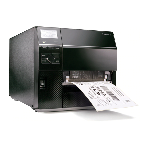
Toshiba B-EX6T Series Key Operation Specification
Hide thumbs
Also See for B-EX6T Series:
- Owner's manual (79 pages) ,
- Quick installation manual (8 pages)

Subscribe to Our Youtube Channel
Related Manuals for Toshiba B-EX6T Series


Summary of Contents for Toshiba B-EX6T Series
- Page 1 TOSHIBA Bar Code Printer B-EX6T Series Key Operation Specification First edition: February 22, 2016 Second edition: July 25, 2016 Third edition: Dec 22, 2017 Fourth edition: May 17, 2019...
-
Page 2: Table Of Contents
Table of Contents Page SCOPE ............................5 OUTLINE ............................ 5 OPERATION PANEL ........................5 OUTLINE OF EACH MODE ......................6 ONLINE MODE ..........................6 4.1.1 Threshold setting mode ........................6 4.1.2 RFID calibration mode ........................6 4.1.3 Information mode ..........................6 USER SYSTEM MODE ........................ - Page 3 DISPLAY PATTERN AND KEY OPERATION FOR SYSTEM MODE ANDUSER SYSTEM MODE ..............................38 LIST BOX WITH SCROLLBAR ....................38 VALUE SETTING SCREEN ......................41 INFORMATION SCREEN ......................43 SENSOR ADJUSTMENT SCREEN ..................... 45 TEMPERATURE DISPLAY SCREEN..................46 FILE SELECTION SCREEN ......................47 INITIAL SETTING WIZARD (NOT AVAILABLE IN JA TYPE) ..........
- Page 4 9.5.30 REAR RIBBON MOTOR ....................... 97 9.5.31 Ribbon Width ..........................98 TEST PRINT ..........................99 9.6.1 PRINT CONDITION ........................99 9.6.2 SLANT LINE (1DOT) (only B-EX4T1) ..................102 9.6.3 SLANT LINE (3DOT) ........................103 9.6.4 CHARACTERS ........................... 104 9.6.5 BARCODE ..........................105 9.6.6 NON-PRINTING ..........................
- Page 5 12.3 Auto Configuration File ....................... 157 12.3.1 Format ............................157 12.3.2 Model Information ........................157 12.3.3 Display Message ......................... 157 12.3.4 Firmware File to be downloaded ....................157 POWER SAVE FUNCTION ....................158 COPYRIGHT©2015 TOSHIBA TEC Corporation All rights reserved...
-
Page 6: Scope
1 SCOPE This specification describes key operations using the keys and the LCD of the B-EX6T series high-end industrial general-purpose bar code printers. Supported model: B-EX6T1/T3, B-EX4T1-QM/CN 2 OUTLINE Key operations are different depending on the printer mode: Online mode in which operations are carried out through the keys and error messages are displayed while the printer is connected to the host such as a PC, and the system mode in which self-diagnosis and setting of various parameters are performed. -
Page 7: Outline Of Each Mode
4 OUTLINE OF EACH MODE This chapter describes the outline of each mode supported by the printer. Refer to each chapter for detailed information. 4.1 ONLINE MODE This mode is mainly used by users (operators). The label or tag can be issued in the online mode. When an error occurs, the help function shows the cause of the error, troubleshooting, and recovery from the error. -
Page 8: System Mode
4.3 SYSTEM MODE This mode is mainly used by service persons or the production department staff for adjustment of the printer before shipment. The system mode contains the menus which might be changed not so frequently. In addition to the parameter setting and fine adjustment menus common to the User System Mode, there are sensor adjustment, interface, RFID, RTC and BASIC setting menus. -
Page 9: General View Of Key Operation
5 GENERAL VIEW OF KEY OPERATION [Power OFF] Power on Online mode [FEED] key Feed one label. [RESTART] key [PAUSE] key Pause state Hold down the [PAUSE] key for a few seconds. Threshold setting mode Hold down the [UP] key for a few seconds. - Page 10 <Example of the LCD display> Pause state Threshold setting mode RFID calibration mode Information mode User system mode System mode Download mode Auto configuration mode Notes: 1. To enter the download mode, system mode or auto configuration mode, keep holding down the specified key until each menu is shown.
-
Page 11: Online Mode
6 ONLINE MODE 6.1 KEY FUNCTION The printer behavior is not guaranteed when undefined key is operated. 6.1.1 Online Mode Screen Function (1) Feedone piece of media to eject one piece of media. [FEED] Use the media to feed to the print start position. If printing is attempted with the media improperly positioned, print data is not printed at the correct position. -
Page 12: Help Screen
6.1.2 Help Screen Function (1) Ends help message screen. [FEED] (1) Ends help message screen. [RESTART] (1) Ends help message screen. [PAUSE] (1) Ends help message screen. [MODE] (1) Ends help message screen. [CANCEL] (2) Return to the previous help page. (3) Ends help message screen. -
Page 13: Led Function
6.2 LED FUNCTION [ONLINE] LED Indicates that the printer is in online state. Flashes when the printer is communicating with the host. Flashes (ON: 250ms. OFF: 250ms.) in synchronization with the ERROR LED when the printer is turned off. Flashes in the power save mode (ON: 1 sec., OFF: 1 sec.) (Note) [ERROR] LED Indicates that the printer is in error state. - Page 14 (Note): 1. Whether to display or hide the 1 and 4 lines of online mode screen can be selected in the system mode. 2. Refer to Section 6.4.2 Icon Display for details. (*1) The number of labels printed is the cumulative number of labels printed after a printer is powered on. Number of labels printed reset to zero when the printer is turned on.
-
Page 15: Icon
6.4.2 Icon Five kinds of icon are displayed in the bottom line of the online mode screen. These icons are displayed only in the online mode screen. Icon Explanation Wireless LAN icon Displayed and used when the wireless LAN module is installed. ... -
Page 16: Online Mode Screen Transition And Operation Example
6.4.3 Online Mode Screen Transition and Operation Example B-EX4T1 C1.6 ONLINE PRINTED 000000 IP:192.168.010.020 Idling or normal issuing When the [RESTART] key is pressed, (TO DO) 123 When the [PAUSE] key the printer resumes printing if there is is pressed while printing: PAUSE remaining data to print. -
Page 17: Help Screen
6.5 HELP SCREEN 6.5.1 Explanation of Help Screen When “Help” is displayed at the lower right of the online mode screen, pressing the [RIGHT] or [ENTER] key causes a help message to be shown. The help message is displayed on the upper four lines. When the message exceeds four lines, the up and down arrows are shown on the scrollbar on the left, and the hidden lines can be displayed by scrolling down. -
Page 18: Help Screen Transition And Operation Example
6.5.2 Help Screen Transition and Operation Example The help screen consists of three pages, which are Help 1, Help 2 and Help 3. Help 1 shows the details of the error, Help 2 shows a troubleshooting, and Help 3 shows how to recover from the error. -
Page 19: Manual Threshold Setting
6.6 MANUAL THRESHOLD SETTING 6.6.1 Outline of Threshold setting When a label stock is printed, the printer automatically corrects the print position by detecting gaps between the labels by using the transmissive sensor to maintain a constant print position. However, when preprinted label stock is used, print positions may not be detected correctly depending on ink type used for preprints. - Page 20 Threshold Setting Operation Example B-EX4T1 C1.6 1. Online mode: Online state ONLINE PRINTED 000000 IP:192.168.010.020 ↓ Press the [PAUSE] key. 2. Online mode: Pause state PAUSE ↓ Hold down the [PAUSE] key for 3 seconds. SELECT MEDIA SENSOR 3. Threshold setting: ▴...
- Page 21 THRESHOLD <REFL.> 6c. Threshold fine Operation is same as 9.7.4 adjustment THRESHOLD LEVEL ( 0.0 4.0 V) Press any of the [PAUSE], [ENTER], and [CANCEL] key. 1)REFL.(PRE-PRINT) 6d. Judgment result (After Result: OK (Mid.) the fine adjustment) Threshol Baseline ◀Adjust Detail▶...
- Page 22 Details of the result Display example Displayed item Explanation 1)REFL.(PRE-PRINT) Sensor type The calibration result and the threshold voltage are Peak : 3.7V Peak value displayed. Threshold : 2.7V Threshold voltage Pressing the [RIGHT] key enables setting a threshold Baseline : 1.3V ...
- Page 23 8) Press the [FEED] key to feed the media. → If a paper jam occurs or the media does not stop at the print start position, retry the threshold setting. Sending Issue command 1) While the judgment result is displayed, press the [FEED] key to terminate the threshold setting. →...
-
Page 24: Rfid Calibration
6.7 RFID CALIBRATION The supported RFID modules and RFID tag types are as follows: Module: B-EX6T1: B-EX706-RFID-U4-R B-EX706-RFID-U4-EU/UA/AU-R B-EX4T1: B-EX700-RFID-U4-EU/US/AU-R Tag: The following tag type only (The others are unusable.) • TSE Web (Supplier: SMARTRAC, Chip: NXP U-Code G2iL) Feed direction Label pitch Label length Label width (mm) -
Page 25: Outline Of The Rfid Calibration
6.7.1 Outline of the RFID Calibration RFID calibration is a function to automatically determine the distance to the optimum write/read position and the AGC value required for properly writing/reading data on/from RFID tags. When the result of an RFID calibration is saved (by pressing the [ENTER] key) while the detected values are shown on the screen, the value obtained through the RFID calibration is set for the CALIB. -
Page 26: Rfid Calibration Operation Example
6.7.2 RFID Calibration Operation Example Note: Be sure to complete the following before performing an RFID calibration. 1) Select a usable antenna position in the system mode. (Refer to Section 6.7.1 Outline of the RFID Calibration.) 2) Place the RFID media at the print start position in advance by performing an automatic calibration. [Online mode] 1. -
Page 27: Information Mode
6.8 INFORMATION MODE 6.8.1 Outline of the Information Mode In the information mode, the total feed amount counted during feed and printing operations is displayed on the LCD in units of centimeter and inch, and printed on request. The feed amount is counted at the end of feed or printing, and saved in the non-volatile memory. Notes: (*1) 1. -
Page 28: Information Mode Operation Example
6.8.2 Information Mode Operation Example B-EX4T1 C1.6 [Online mode] 1. Normal state ONLINE PRINTED 000000 IP:192.168.010.020 ↓ Press the [PAUSE] key. [Online mode] 2. Pause state PAUSE ↓ Hold down the [UP] key for 3 seconds. BCP COUNTER [Information mode] 477984cm Feed amount is Pressing the [CANCEL] key returns... -
Page 29: Information Mode Print Sample
6.8.3 Information Mode Print Sample <Print sample> B-EX6T1/T3, B-EX4T1-QM/CN: Max. number of digits: 74 mm, Center-aligned TOTAL COUNTER LIST MM-dd-yyyy hh:mm xxxxxxxxxxxxxxxx S/N:zzzzzzzzzzzzzzzzzzzzzzzzzzzzzzzz PRINTER aaaaaaaaacm bbbbbbbbb.binch Max. number of digits: 74 mm Effective print width <Print data> Item Information Range 1st line Title TOTAL COUNTER LIST... -
Page 30: Job Cancellation
6.9 JOB CANCELLATION 6.9.1 Outline of the Job Cancellation The [CANCEL] key enables cancellation of subsequent print jobs. Holding down the [CANCEL] key for 3 seconds while the printer is in an error* or pause state causes the printer to start a quick reset and shift to the online mode. As long as the [CANCEL] key is held down, the data in the receive buffer is all discarded. -
Page 31: Lcd Messages And Led Indications
6.10 LCD MESSAGES AND LED INDICATIONS Acceptance of Restoration by LCD Message Status Request indications the [RESTART] line Printer status and Reset (English) Command ERROR Yes/No LINE Yes/No ● In the online mode In the online mode ● ONLINE (Communicating) In the online mode with a ribbon... - Page 32 ▪ An abnormal condition occurred with the sensor for determining the torque of the ribbon motor. ● 12 RIBBON ERROR ▪ A ribbon jam occurred. ▪ The ribbon has been torn. ▪ The ribbon has not been set. An overflow error has occurred in ●...
- Page 33 Initializing DHCP CLIENT. 24 DHCP CLIENT INIT… ● ● * Only when DHCP is enabled The printer did not succeed in RFID WRITE writing data onto the RFID tag after ● ERROR having retried for the specified times. RFID ERROR The printer cannot communicate ●...
- Page 34 Notes 1. When the ribbon near end detection is enabled, the error LED blinks at a 1-second interval (ON for 500 msec. OFF for 500 msec.) while the printer is in a ribbon near end state. 2. When there is command error in received commands, up to 42 bytes of error command, starting from the command code, are shown on 3 and 4 lines of the LCD.
- Page 35 LCD message (2 line) English German French ONLINE ONLINE PRETE HEAD OPEN Kopf offen. TÊTE OUVERTE PAUSE PAUSE PAUSE COMMS ERROR Kommunikations-Fehler ERREURS DE COMMUNICAT PAPER JAM PAPIERSTAU BOURRAGE PAPIER CUTTER ERROR Messer Fehler ERREUR MASSICOT NO PAPER Kein Papier. PAS DE PAPIER NO RIBBON KEIN FARBBAND...
- Page 36 Dutch Spanish Japanese IN LIJN PREPARADA PRINTKOP OPEN. CABEZAL ABIERTO PAUZE PAUSA COMMUNICATIE FOUT ERROR DE COMUNICACION PAPIER STORING. ATASCO DE PAPEL FOUT SNIJMES ERROR DE CORTADOR GEEN PAPIER SIN PAPEL GEEN LINT SIN CINTA PRINTKOP OPEN. CABEZAL ABIERTO FOUT PRINTKOP ERROR DE CABEZAL PRINTKOP OVERHIT.
- Page 37 Italian Portuguese Chinese ONLINE On Line PREPARADA 打印头打开 Testina Aperta CABECA ABERTA 暂停 PAUSA PAUSA 通讯错误 Errore Seriale ERRO DE COMUNICACAO 卡纸 Carta inceppata PAPEL ENCRAVADO 切刀错误 Errore Taglierina ERRO DE CORTADOR 缺纸 Manca Carta SEM PAPEL 无碳带 Manca Nastro SEM FITA 打印头打开...
- Page 38 Korean Turkish Polish 온라인 ONLINE ONLINE 헤드 열림 Kafa açık OTWARTA GŁOWICA. PAUSE PAUSE PAUZA 통신 에러. İLETİŞİM HATASI BŁĄD COMMS 용지 잼 Kağıt sıkışması ZACIĘCIE PAPIERU 커터 에러 KESİCİ HATASI BŁĄD NOŻA 종이가 없습니다. Kağıt yok BRAK PAPIERU 리본이 없습니다. BRAK TAŚMY Ribbon yok 헤드...
-
Page 39: Display Pattern And Key Operation For System Mode Anduser System Mode
7 DISPLAY PATTERN AND KEY OPERATION FOR SYSTEM MODE AND USER SYSTEM MODE 7.1 LIST BOX WITH SCROLLBAR The list box is used for displaying the menus or items to be selected. It is comprised of the following parts. SYSTEM MODE C1.6 Title ▲... - Page 40 Key function (value setting display) Substitute Key Function [MODE] None Returns to the top menu without saving changes. [CANCEL] [FEED] + [RESTART] Returns to the upper-level menu without saving changes. [ENTER] [PAUSE] Saves the changes and returns to the upper-level menu. [UP] [RESTART] Moves the cursor upward.
- Page 41 Notes: 1. Cursor position when shifting from upper-level menu to its sub menu When shifting from upper-level menu to its sub menu, the cursor is positioned at the topmost item except for RFID setting menu (because the RFID menu items show the setting value). 2.
-
Page 42: Value Setting Screen
7.2 VALUE SETTING SCREEN The value setting screen is used for setting a value by increasing or decreasing it. It is comprised of the following parts. Display example FEED ADJ. Title Setting range +0.0 Setting value (-50.0 - +50.0)mm Notes: 1. - Page 43 Key operation (Setting screen with multiple fields (horizontal)) Substitute Key Function [MODE] None Return to the top menu without saving changes. [CANCEL] [FEED] + [RESTART] Return to the upper-level menu without saving changes. [ENTER] [PAUSE] Save the changes and returns to the upper-level menu. [UP] [RESTART] Increases the setting value by specified step.
-
Page 44: Information Screen
7.3 INFORMATION SCREEN The information screen is used when there is no settings are configured. It is comprised with the following: Display example Title Information Display Scroll RFID tag read Key function Substitute Key Function [MODE] None Displays the top menu. [CANCEL] [FEED] + [RESTART] Displays the upper-level menu. - Page 45 Key function (RFID tag read) Substitute Key Function [MODE] None Displays the top menu without saving changes. [CANCEL] [FEED] + [RESTART] Displays the upper-level menu without saving changes. [ENTER] [PAUSE] RFID tag is read again. [UP] [RESTART] Displays the data of the previous tag. The display does not change when the first tag data is being shown.
-
Page 46: Sensor Adjustment Screen
7.4 SENSOR ADJUSTMENT SCREEN The sensor adjustment screen is used only when the level of the media sensors on the printer is required to be adjusted. It is comprised with the following : Display example REFLECTIVE SENSOR Title 4.3V Message Sensor level Set a blank label [ENTER] for 3sec... -
Page 47: Temperature Display Screen
7.5 TEMPERATURE DISPLAY SCREEN Temperature display screen is used only for displaying the print head temperature and ambient temperature. It is comprised with the following : Display example TEMPERATURE Title Print head temperature THERMAL HEAD 20℃ OPEN-AIR 13℃ Ambient temperature Display Display of temperatures TEMPERATURE... -
Page 48: File Selection Screen
7.6 FILE SELECTION SCREEN File selection screen is used for selecting a file when copying data from USB memory to the printer. It is comprised with the following : Display example Title Scroll bar Scroll lines (4 lines) Note: 1. The scrollbar knob on the file selection screen is not displayed regardless of the number of files. There are two types of file selection screensas follows. -
Page 49: Initial Setting Wizard (Not Available In Ja Type)
8 Initial Setting Wizard (Not available in JA Type) Only when the printer is started for the first time after clears a parameter, the initial setting wizard is started. This wizard enables setting the basic parameters, such as the LCD language and print mode, required for various printer settings. - Page 50 6.-1-1 INITIAL CONFIGURATION Finish FINISH? ◀Prev ENTER:Finish ↓ [ENTER] key. 7. The settings are saved. 6.-2 When “OFF” is selected for CALIBRATE 6.-2-1 Choose an option with the PAPER DETECT FEED/GAP ▲ Media detection [UP] or [DOWN] key. CONTINUOUS LABEL/GAP BLACK MARK ▼...
- Page 51 Key functions (Wizard screen) Substitute key Function [MODE] None Displays the top page without saving the changes. [CANCEL] [FEED] + [RESTART] Displays the upper level menu without saving the changes. [ENTER] [PAUSE] In the case of option selection screen, save the changes and displays the next screen.
-
Page 52: System Mode
9 SYSTEM MODE 9.1 OUTLINE OF THE SYSTEM MODE 1. The printer enters the system mode with the following operations. ・ While the printer power is off, perform either of the following operations: ・ Turn on the printer while holding down the [FEED] and [PAUSE] key at the same time. ・... -
Page 53: Reflecting The System Mode Settings To The Printer
Outline of the top menu <0>RESET Restart the printer. <1>DIAGNOSTIC Perform self diagnosis, print out the result, check for the print head broken elements. <2>SET PARAMETERS Set the parameters for printer functions <3>TEST PRINT Test print quality by printing slant lines, characters and barcodes. <4>SENSOR Display the ambient temaprature and print head temparature, and adjust each level of the media sensors. -
Page 54: Maintenance Counter
9.4.1 MAINTENANCE COUNTER The following table shows the menu structure from the top menu of the system mode to MAINTENANCE COUNTER. Menu item <1>DIAGNOSTIC MAINTENANCE COUNTER THERMAL TRANSFER DIRECT THERMAL DISPLAY Notes: 1. The MAINTENANCE COUNTER enables selecting whether to print or display the self-diag. test result (maintenance counter data and parameter settings). - Page 55 CHECKING & PRINT Maintenance Counter/Parameter Settings Print Contents. PRINTING When the printing is completed. (Normal end) PRINT TYPE C1.6 1. When the printing is completed, PRINT TYPE menu is ▲ displayed again. THERMAL TRANSFER DIRECT THERMAL DISPLAY ▼ When an error occurred during printing CHECKING &...
- Page 56 9.4.1.1 Maintenance Counter/Parameter Settings Print Contents B-EX6T1/3 SYSTEM PASSWORD [OFF] << COUNTER >> << STORAGE AREA >> TOTAL FEED 3.7km [QM] TTF AREA 0KB] FEED 2.4km EXT CHR AREA 0KB] FEED1 1.3km BASIC AREA 0KB] FEED2 0.0km PC SAVE AREA 0KB] FEED3 0.0km...
- Page 57 B-EX4T1-QM/CN << COUNTER >> BASIC AREA 0KB] TOTAL FEED 3.7km [QM] PC SAVE AREA 0KB] FEED 2.4km << USB >> FEED1 1.3km SERIAL NUMBER [DISABLE] FEED2 0.0km [XXXXXXXXXXXX] FEED3 0.0km << RS-232C >> FEED4 0.0km BAUD RATE [9600] PRINT 2.4km DATA LENGTH PRINT1 1.3km...
- Page 58 Print condition: Label length 490 mm to 530 mm (length varies on the model) Print method User setting Sensor type None Speed 203 dpi: B-EX6T1/T3-G 5 ips 305 dpi: B-EX6T1/T3-T 5 ips 203 dpi: B-EX4T1-G 6 ips 305 dpi: B-EX4T1-T 5 ips Print count Issue mode...
- Page 59 [Counting condition] The number of times the print head moves up and down with the solenoid for ribbon save is counted. (A set of up and down is counted as one.) The head up/down count is saved every 4 head up/down operations. RIBBON [Description] Ribbon motor drive time [Range] 0 to 2000 hours...
- Page 60 << PARAMETER SETTINGS >> Item Description Value to be printed MEDIA LOAD [ ] [Description] Media feed to the print start position [Values to be printed] OFF: Disabled. STD: Feeds the detected gap/mark to the print start position. ECO: Feeds a gap/mark positioned between the print head and the media sensor, if any, to the print start position.
- Page 61 The ribbon saving module is used.(Head lever position: “TAG”) ON:TAG: ON:LABEL: The ribbon saving module is used. (Head lever position: “LABEL”) PRE PEEL OFF [ ] [Description] Whether to enable the pre-peel-off function [Values to be printed] OFF: Enabled. Disabled. BACK FEED SPEED [ ] [Description] Reverse feed speed [Values to be printed]...
- Page 62 PEEL OFF STATUS [ ] [Description] Whether to send a peel-off wait status to the host [Values to be printed] OFF: Not sent. sent. USB I/F STATUS [ ] [Description] Whether to send a response to the host via USB [Values to be printed] OFF: Not sent.
- Page 63 [Values to be printed] TYPE1: Compatible: Compatible with the current version TYPE2: Special Spec: Special specification XML [ ] [Description] XML data printing [Values to be printed] OFF: Disabled. STD: Standard specification ORACLE: Specification for Oracle SAP: Specification for SAP STD EXTERNAL: Standard specification (External memory is used.) ORACLE EXTERNAL: Specification for Oracle (External memory is used.)
- Page 64 rsv1: (Reserved1): Reserved rsv2: (Reserved2): Reserved rsv3: (Reserved3): Reserved rsv4: (Reserved4): Reserved rsv5: (Reserved5): Reserved rsv6: (Reserved6): Reserved rsv7: (Reserved7): Reserved rsv8: (Reserved8): Reserved rsv9: (Reserved9): Reserved Note: If “CN” is selected for the parameter clear destination, the ENERGY TYPE parameter is not displayed on the menu and unable to be set in the system mode and user system mode.
- Page 65 OFF: Hidden. Displayed. PRINTED COUNTER [ ] [Description] Whether to display the number of labels printed [Values to be printed] OFF: Hidden. Displayed. IP ADDRESS [ ] [Description] Whether to display IP address [Values to be printed] OFF: Hidden. Displayed. CONTRAST [ ] [Description] LCD contrast [Values to be printed]...
- Page 66 << USB >> SERIAL NUMBER [1] [2] [Description 1] Whether to enable USB serial number [Values to be printed] DISABLE: Disabled. ENABLE: Enabled. [Description 2] USB serial number << RS-232C >> BAUD RATE [ ] [Description] Baud rate [Values to be printed] 2400: 2400bps 4800:...
- Page 67 << CENTRO >> ACK/BUSY [ ] [Description] Centronics ACK/BUSY timing [Values to be printed] Rising edge: A rise of ACK signal and a release of BUSY occur at the same time. Trailing edge: A fall of ACK signal and a release of BUSY occur at the same time. INPUT PRIME [ ] [Description] Reset process when the nInit signal is ON [Values to be printed]...
- Page 68 << LAN/WLAN >> LAN/WLAN [ ] [Description] LAN type [Values to be printed] OFF: Disabled. AUTO: Automatically selected.(If WLAN is installed, LAN is not available.) LAN: Wired LAN WLAN: Wireless LAN SNMP [ ] [Description] Whether to enable SNMP [Values to be printed] OFF: Disabled.
- Page 69 [Values to be printed] Max. 64 characters DHCP HOST NAME [ ] [Description] DHCP host name (ASCII) [Values to be printed] Max. 32 characters WLAN STANDARD [ ] (only B-EX4T1) [Description] WLAN Standard [Values to be printed] 11b/g: 802.11b/g CONNECTION MODE [ ] [Description] Wireless LAN: Connection setting [Values to be printed] B-EX6T1/T3 AP MODE...
- Page 70 [Description] Wireless LAN: Authentication method [Values to be printed] B-EX6T1/T3 OPEN Note: This parameter is set by using the Printer Setting Tool. SHARED [Values to be printed] B-EX4T1 OPEN Note: This parameter is set by using the Printer Setting Tool. SHARED NETWORK EAP 802.1X SUPPLICANT [ ]...
- Page 71 [Description] Wireless LAN: 11g connection channel setting [Values to be printed] 1 to 13 802.11g BAUD RATE [ ] (only B-EX4T1) [Description] Wireless LAN: 11g baud rate setting [Values to be printed] 5.5M WINS [ ] [Description] Whether to enable WINS [Values to be printed] OFF: Disabled.
- Page 72 << RFID >> MODULE TYPE [ ] [Description] RFID module type [Values to be printed] B-EX6T1/T3 NONE: No RFID kit is installed. HF band(H1) HF band(H2) UHF band(U2/U4) B-EX706-RFID-U4-EU/US/AU-R, B-EX706-RFID-U4-R [Values to be printed] B-EX4T1 NONE: No RFID kit is installed. B-EX700-RFID-H1-QM-R use B-EX700-RFID-H2-R, B-EX700-RFID-H3-QM-R use B-EX700-RFID-U2-EU/US-R, B-EX700-RFID-U4-R,...
- Page 73 [Values to be printed 1] 0 to 255 times [Description 2] Timeout for tag read retry [Values to be printed 2] 0 to 9.9 sec. WRITE RETRY [ ] [Description 1] The number of times tag write is retried [Values to be printed 1] 0 to 255 times [Description 2] Timeout for tag write retry [Values to be printed 2]...
- Page 74 [Description 3] Auto unlock function Note: Only when “ON (ACCESS PASSWORD)” is selected for TAG CHECK [Values to be printed 3] OFF: Disabled. Enabled. MULTI WRITE [ ] [Description] Multi-word write *This setting is valid if RFID module Z is #20A or later [Values to be printed] OFF: Disabled.
- Page 75 << RTC >> BATTERY CHECK [ ] [Description] Battery check [Values to be printed] OFF: Disabled. Enabled. RENEWAL [ ] [Description] Time update timing [Values to be printed] start of JOB: Every batch every PAGE: Every page...
-
Page 76: Auto Diagnostic
9.4.2 AUTO DIAGNOSTIC The procedure for printing the self-diagnosis result is the same as that for the maintenance counter/parameter setting data described in 9.4.1 MAINTENANCE COUNTER. The following table shows the menu structure from top menu of the system mode to AUTO DIAGNOSTIC. The menu structure of AUTO DIAGNOSTIC Menu item <1>DIAGNOSTIC... - Page 77 B-EX4T1-QM/CN PROGRAM B-EX4T1-G MODEL B-EX4T1-TS12-QM-R PRINTER S/N 2317A232688 MAIN XXXXXXXXX C3.0 :F100 BOOT XXXXXXXXX V1.0B :0000 WMON XXXXXXXXX V1.0 :6100 FONT AE00 ZFONT 7600 KANJI GOTHIC :C300 CHINESE :F700 EEPROM 256B SDRAM 32MB SENSOR1 00000000,00000111 SENSOR2 [H]23゚C [A]22゚C [R]4.2V [T]2.5V [E]0.6V PE LV.
-
Page 78: Head Check
9.4.3 HEAD CHECK The print head check procedure is the same as that for the maintenance counter data described in 9.4.1 MAINTENANCE COUNTER. The following table shows the menu structure from the top menu of the system mode to HEAD CHECK. The menu structure of HEAD CHECK Menu item <1>DIAGNOSTIC... -
Page 79: Set Parameters
9.5 SET PARAMETERS Contents of the SET PARAMETERS menu Menu item <2>SET PARAMETERS MEDIA LOAD FEED KEY MOVE TO TEAROFF FW/BK ACT. RIBBON SAVE HEAD UP CUT/RWD PRE PEEL OFF BACK FEED SPEED AUTO HEAD CHECK RIBBON NEAR END PAPER/RBN END CALIBRATE POWER SAVE TIME CODE PAGE... -
Page 80: Feed Key
・ ECO+Backfeed After performing above-mentioned ECO, the printer feeds the media backward for the label pitch length while raising the print head if the following conditions are satisfied. Notes: 1. This function is enabled only when the sensor type is set to other than “None”. 2. -
Page 81: Fw/Bk Act
9.5.4 FW/BK ACT. ・ MODE1: Normal: The printer waits for a next issue after media is forwarded fixed length. B-EX6T1/T3: 16.5mm B-EX4T1: 13.7mm ・ MODE2: SHORT CUT LAB: When the thermal transfer method and cut issue are selected, the printer feeds 6-mm media backward, then waits for next issue with media forwarded 3-mm. -
Page 82: Pre Peel Off
・ OFF The head-up function is disabled during cut issue or the rewinder is not used. ・ ON The head-up function is enabled during cut issue or the rewinder is used. Notes: 1. Whether or not to activate the head up action in the cut issue or to use the Rewinder in the batch or strip issue is selected. -
Page 83: Paper/Rbn End
9.5.11 PAPER/RBN END ・ Stop immediately When a label end or ribbon end status is detected, the printer stops immediately. ・ Complete current When a label end or ribbon end status is detected, the printer prints the current label as far as possible, then stops. Notes: 1. - Page 84 (2) Ribbon end detection: In the case unfinished label length is 30 mm or more Printer behavior The printer prints for 20 mm and stops printing with error. * Printing of the half-finished label is not completed. LCD message “NO RIBBON”...
-
Page 85: Calibrate
<Example> Specified number of labels = 5, A ribbon end is detected while the 3rd label is printed. Unfinished label length is less than 30 mm label … Finished (*) Printing: 1 Printing: 2 label ... Finished (*) label … After an error is detected, printing is completed. Finished (*) Printing: 3 Stop with error …... -
Page 86: Power Save Time
6. The printer feeds about 160 mm long media to detect a black mark/gap and determine the threshold. When the printer has detected more than one black marks/gaps during this 160-mm media feed, the printer measures the media pitch and stops the automatic calibration 1 mm short of the bottom of a black mark or gap. 7. -
Page 87: Code Page
9.5.14 CODE PAGE ・ PC-850 ・ PC-852 ・ PC-857 ・ PC-8 ・ PC-851 ・ PC-855 ・ PC-1250 ・ PC-1251 ・ PC-1252 ・ PC-1253 ・ PC-1254 ・ PC-1257 ・ LATIN9 ・ Arabic ・ PC-866 ・ UTF-8 9.5.15 ZERO FONT ・ 0 Without slash ・... -
Page 88: Peel Off Status
9.5.17 PEEL OFF STATUS ・ OFF Disabled ・ ON Enabled 9.5.18 KANJI CODE ・ TYPE1:Windows: Windows code ・ TYPE2:Original: Original code 9.5.19 EURO CODE Max. Integer Decimal Unit of Min. value Step Display Sign 0-padding value digit place measure 0xFF 0x20 Hex. -
Page 89: Feed Adj
9.5.21 FEED ADJ. Max. Integer Decimal Unit of Min. value Step Display Sign 0-padding value digit place measure +50.0 -50.0 Decimal Exist None +0.0 mm Print start One label position +3.0 mm Print start One label position -3.0 mm Paper feed direction One label Print start position Note: The feed amount fine adjustment value is the sum of the fine adjustment values set in the system... -
Page 90: Cut Adj
9.5.22 CUT ADJ Max. Integer Decimal Unit of Min. value Step Display Sign 0-padding value digit place measure +50.0 -50.0 Decimal Exist None +0.0 mm Cut position +3.0 mm Cut position -3.0 mm Cut position Paper feed direction Notes: 1. The cut position fine adjustment value is the sum of the fine adjustment values set in the system mode (by key operation) and set by command (from the PC). - Page 91 [Method 2] Adjust the cut position fine adjustment value. The cut position fine adjustment value can be calculated using the following method. If a calculated value does not work to feed the media backward to the proper home position, the cut position needs to be re-adjusted with another value.
- Page 92 3. Procedure for label having less than the min. label pitch for each issue speed when the rotary cutter is used When the following conditions are all met, the cut operation for the last label to be cut is performed as follows.
-
Page 93: Back Adj
9.5.23 BACK ADJ. Max. Integer Decimal Unit of Min. value Step Display Sign 0-padding value digit place measure +9.9 -9.9 Decimal Exist None +0.0mm Print start position (Home position after a back feed) +3.0mm Print start position (Home position after a back feed) -3.0mm Print start position (Home position after a back feed) -
Page 94: Adjust
9.5.24 X ADJUST Max. Integer Decimal Unit of Min. value Step Display Sign 0-padding value digit place measure +99.5 -99.5 Decimal Exist None Notes: 1. The X ADJUST parameter can fine adjust the print position in X-coordinate (horizontal direction). The fine adjustment shall be performed so that the print position falls within the effective print width. -
Page 95: Tone Adj.
Notes: 1. “Generic” is a setting for securing the print quality equivalent to that of the B-SX, but it is not effective at the print speed of 10 ips or faster. If 10 ips or faster print speed is specified, the printer operation is not guaranteed. -
Page 96: Tone Adj.
value exceeds the print head rating, it is automatically corrected. 3. The factory default is +0step. B-EX4T1 Max. Integer Decimal Unit of Min. value Step Display Sign 0-padding value digit place measure Decimal Exist None Step Remarks: 1. Setting a value in the positive (+) direction, the print tone becomes darker. And, setting a value in the negative (-) direction, the print tone becomes lighter. -
Page 97: Ribbon Torque
9.5.28 RIBBON TORQUE ・ Normal ・ Low ・ Reserved1 (only B-EX6T1/T3) 9.5.29 FRONT RIBBON MOTOR The menu structure of FRONT RIBBON MOTOR menu Menu item <2>SET PARAMETERS FRONT RIBBON MOTOR Normal Torque Low Torque Reserved1 (only B-EX6T1/T3) 9.5.29.1 Normal Torque Max. -
Page 98: Rear Ribbon Motor
9.5.30 REAR RIBBON MOTOR The menu structure of REAR RIBBON MOTOR menu Menu item <2>SET PARAMETERS REAR RIBBON MOTOR Normal Torque Low Torque Reserved1 (only B-EX6T1/T3) 9.5.30.1 Normal Torque Max. Integer Decimal Unit of Min. value Step Display Sign 0-padding value digit place... -
Page 99: Ribbon Width
9.5.31 Ribbon Width NORM: Normal rsv1: (Reserved1) rsv2: (Reserved2) rsv3: (Reserved3) rsv4: (Reserved4) rsv5: (Reserved5) rsv6: (Reserved6) rsv7: (Reserved7) rsv8: (Reserved8) rsv9: (Reserved9) -
Page 100: Test Print
9.6 TEST PRINT Contents of TEST PRINT menu Menu item <3>TEST PRINT PRINT CONDITION SLANT LINE(1DOT) (only B-EX4T1) SLANT LINE(3DOT) CHARACTERS BARCODE NON-PRINTING FACTORY TEST AUTO PRINT(TRANS.) AUTO PRINT(REFL.) 9.6.1 PRINT CONDITION The menu structure of PRINT CONDITION Menu item <3>TEST PRINT PRINT CONDITION ISSUE COUNT... - Page 101 6. When the transmissive sensor is selected, the gap between labels shall be 3 mm. Notes: 1. B-EX4T1 does not support the use of rotary cutters at 10 ips or more, so if the rotary cutter is attached (with or without cutting), specifying 10 ips or more will correct the operation to 8 ips. 2.
- Page 102 9.6.1.3 SENSOR ・ NONE ・ TRANSMISSIVE ・ REFLECTIVE ・ MANUAL TRANS. ・ MANUAL REFL. 9.6.1.4 PRINT TYPE ・ THERMAL TRANSFER ・ DIRECT THERMAL 9.6.1.5 ISSUE TYPE ・ NO CUT ・ WITH CUT ・ PEEL OFF 9.6.1.6 LABEL PITCH Max. Integer Decimal Unit of Min.
-
Page 103: Slant Line (1Dot) (Only B-Ex4T1)
9.6.2 SLANT LINE (1DOT) (only B-EX4T1) 1-dot slant lines Magnification of slant lines 1-dot slant lines (Black area ratio: 16.7%) -
Page 104: Slant Line (3Dot)
9.6.3 SLANT LINE (3DOT) 3-dot slant lines Magnification of slant lines 3-dot slant lines (Black area ratio: 16.7%) -
Page 105: Characters
9.6.4 CHARACTERS Gothic + Mincho Gothic + Chinese 9.6.5... -
Page 106: Barcode
9.6.5 BARCODE 9.6.6 NON-PRINTING The printer feeds blank label. 9.6.7 FACTORY TEST... -
Page 107: Auto Print (Trans.)
9.6.8 AUTO PRINT (TRANS.) The factory test print is performed on the following conditions, therefore, the parameter settings and the print density fine adjustment value are ignored. Key functions after printing of each test pattern are as follows. [ENTER] key (or its substitute key): Next printing is performed. -
Page 108: Sensor
9.7 SENSOR Contents of SENSOR menu Menu item <4>SENSOR TEMPERATURE ADJUSTMENT THRESHOLD SELECT THRESHOLD LEVEL 9.7.1 TEMPERATURE The ambient temperature and print head temperature are displayed. Only when the temperature is below zero, the symbol of minus (-) is displayed. The display is updated every 200 msec. -
Page 109: Threshold Select
is shown on the right side of the voltage. If the registration failed due to sensor failure, “SENSOR ERROR” is displayed and the ERROR LED turns on. The ERROR LED turns off when the upper-level menu is displayed. The setting range is as below. Transmissive sensor 0.0 V to 5.0 V 9.7.2.3 PAPER END LEVEL... -
Page 110: Threshold Level
9.7.4 THRESHOLD LEVEL The menu structure of THRESHOLD LEVEL menu Menu item <2>SET PARAMETERS THRESHOLD LEVEL REFLECT TRANS. 9.7.4.1 REFLECT Integer Decimal Unit of Max. value Min. value Step Display Sign 0-padding digit place measure Decimal None None If “0.0 V” is set, the value “0.0 V” is automatically corrected to the initial value “1.0 V”. Note: 9.7.4.2 TRANS. -
Page 111: Ram Clear
9.8 RAM CLEAR Contents of RAM CLEAR menu Menu item <8>RAM CLEAR NO RAM CLEAR MAINTE.CNT CLEAR PARAMETER CLEAR 9.8.1 NO RAM CLEAR This option is provided for users who access this menu by mistake, and intended to exit from the RAM clear menu without performing any RAM clear. -
Page 112: Parameter Clear
2. LCD message while a maintenance counter clear is performed Display ALL COUNTER CLEAR... While clearing ALL COUNTER After the maintenance counter COMPLETED clear is completed Turn off the printer 3. After the maintenance counter clear is completed, turn off the printer when “COMPLETED. Turn off the printer”... - Page 113 3. Parameter settings to be cleared and the initial values set after parameter clear Settings printed on the maintenance counter/parameter setting data printout <<ADJUST>> Item Description Initial value [PC] / [KEY] Feed amount fine adjustment value [PC] +0.0mm [KEY] +0.0mm FEED Cut position/Strip position fine adjustment [PC] +0.0mm [KEY] +0.0mm...
- Page 114 Whether to QM TYPE RIBBON SAVE POSITION1 enable the B-EX6T1/T3 CN TYPE ribbon JA TYPE POSITION1 saving QM TYPE function CN TYPE B-EX4T1 JA TYPE PRE PEEL OFF Whether enable pre-peel-off function BACK FEED SPEED Reverse feed speed (Note) CALIBRATION Auto calibration CODE PAGE Character code selection...
- Page 115 << PANEL >> Item Description Initial value LANGUAGE LCD message QM TYPE ENGLISH language JA TYPE JAPANESE CN TYPE Simplified CHINESE MODEL NAME Whether to display the model name PRINTED COUNTER Whether to display the number of labels printed IP ADDRESS Whether to display the IP address CONTRAST Contrast of the LCD...
- Page 116 << LAN/WLAN >> B-EX6T1/T3 Item Description Initial value LAN/WLAN Selection of LAN type AUTO SNMP SNMP IP ADDRESS Printer IP address Not cleared. SUBNET MASK Subnet mask Not cleared. GATEWAY ADDRESS Gateway address Not cleared. QM TYPE SOCKET PORT Whether to enable Not cleared.
- Page 117 802.11g BAUD RATE WLAN: 11g baud rate setting WINS Whether to enable WINS WINS IP ADDRESS WINS IP address 000.000.000.000 Whether to enable LPR << RFID >> Item Description Initial value MODULE TYPE RFID module type NONE TAG TYPE RFID tag type NONE RF CHANNEL RFID channel setting...
- Page 118 Settings not printed on the maintenance counter/parameter setting data printout System mode: <12>Z-MODE Item Initial value Z-MODE User system mode: <5>SHOW ISSUE COND. B-EX6T1/T3 Item Initial value (Note) Sensor TRANSMISSIVE Mode BATCH Print Speed 203 dpi: 5 ips 305 dpi: 5 ips (Note) Ribbon RBN w/o save...
-
Page 119: Interface
9.9 INTERFACE Contents of INTERFACE menu Menu item <6>INTERFACE LAN/WLAN RS-232C CENTRONICS EXP.I/O 9.9.1 LAN/WLAN The menu structure of LAN/WLAN Menu item <6>INTERFACE LAN/WLAN LAN/WLAN BASIC INFORMATION IP ADDRESS SUBNET MASK GATEWAY ADDRESS DHCP DHCP CLIENT ID DHCP HOST NAME WINS WINS ADDRESS SOCKET PORT... - Page 120 9.9.1.3 IP ADDRESS IP address is displayed and set. 9.9.1.4 SUBNET MASK Subnet mask is displayed and set. 9.9.1.5 GATEWAY ADDRESS Gateway address is displayed and set. 9.9.1.6 DHCP Select whether to enable DHCP. ・ OFF ・ ON 9.9.1.7 DHCP CLIENT ID Enter a DHCP client ID with Hex.
- Page 121 9.9.1.14 WLAN B-EX6T1/T3 The menu structure of WLAN Menu item <6>INTERFACE LAN/WLAN WLAN CONNECTION MODE ESSID WEP DEFAULT KEY 802.11bgn CHANNEL 9.9.1.14.1 CONNECTION MODE ・ AP MODE ・ INFRASTRUCTURE Note: For the combinations of WLAN connection mode and authentication, refer to the Network Specification, Section 9.7 Parameter Setting.
- Page 122 B-EX4T1 The menu structure of WLAN Menu item <6>INTERFACE LAN/WLAN WLAN WLAN STANDARD CONNECTION MODE ESSID WEP DEFAULT KEY 802.11b CHANNEL 802.11b BAUD 802.11g CHANNEL 802.11g BAUD 9.9.1.14.5 WLAN STANDARD ・ 802.11b/g ・ 802.11b ・ 802.11g 9.9.1.14.6 CONNECTION MODE ・ ADHOC ・...
- Page 123 9.9.1.14.11 802.11g CHANNEL Max. Integer Decimal Unit of Min. value Step Display Sign 0-padding value digit place measure Decimal None None None 9.9.1.14.12 802.11g BAUD ・ 54 Mbps ・ 48 Mbps ・ 36 Mbps ・ 24 Mbps ・ 18 Mbps ・...
-
Page 124: Usb
9.9.2 USB The menu structure of USB Menu item <6>INTERFACE USB SERIAL ID USB I/F STATUS 9.9.2.1 USB SERIAL ID ・ OFF ・ ON 9.9.2.2 USB I/F STATUS ・ OFF: No response is returned. ・ ON: Returns a response to the host via USB. Notes: 1. - Page 125 9.9.3.1 BAUD RATE ・ 2400 bps ・ 4800 bps ・ 9600 bps ・ 19200 bps ・ 38400 bps ・ 115200 bps 9.9.3.2 DATA LENGTH ・ 8 bits ・ 7 bits 9.9.3.3 STOP BIT ・ 1 bit ・ 2 bits 9.9.3.4 PARITY ・...
-
Page 126: Centronics
9.9.4 CENTRONICS The menu structure of CENTRO. Menu item <6>INTERFACE CENTRONICS ACK/BUSY INPUT PRIME PLUG & PLAY 9.9.4.1 ACK/BUSY ・ Rising edge ・ Trailing edge 9.9.4.2 INPUT PRIME ・ ・ 9.9.4.3 PLUG & PLAY ・ ・ Note: Plug & play function of USB is always enabled regardless of this setting. 9.9.5 EXP.I/O ・... -
Page 127: Rfid
9.10 RFID Contents of RFID menu Menu item <7>RFID TEST MODULE RETRY UHF SETTING OTHER CARRIER SENSE 9.10.1 TEST RFID tag data related to the test is read. Menu item <7>RFID TEST ID READ 9.10.1.1 ID READ The printer enters the read test mode, and a read test is performed each time the [ENTER] key is pressed. When the data of a tag can be read, it is displayed on the LCD. -
Page 128: Module
・ The number of tag being read/The total number of tags read (Mostly, only 1 tag is read.) ・ For the UHF module, AGC value of the read tag is displayed with decimal number. ・ Data displayed on the 3rd and 4th lines are expressed with hex. code. (16 digits x 2 lines = 32 digits) The displayed data differs depending on the module type. - Page 129 ・ HF band(H2) B-EX700-RFID-H2-R B-EX700-RFID-H3-QM-R ・ UHF band (U2/U4) B-EX700-RFID-U2-EU-R (Europe,India) B-EX700-RFID-U2-US-R (U.S.A, Australia, Taiwan, Korea) B-EX700-RFID-U4-R (Japan) B-EX700-RFID-U4-EU-R (Europe) B-EX700-RFID-U4-US-R (Korea) B-EX700-RFID-U4-AU-R (Australia) U4 module preinstall model (B-EX4T1/T2-GS18/TS18-CN-R) (China) Note: This setting will become effective after the printer power is turned off, and back to on. 9.10.2.2 COUNTRY When the module type is set to “U4”, the country code of the currently installed module is displayed.
- Page 130 *1: Selectable country codes differ depending on the RFID module type. Multiple country codes may be displayed when setting a country code, but be sure to select the country where the RFID module is used. Setting a different country code is prohibited. For the selectable country codes, refer to Section 9.4.2.1 Module version and LCD message.
-
Page 131: Retry
9.10.3 RETRY The parameters related to retry are set. The menu structure of RETRY menu Menu item <7>RFID RETRY RETRY POSITION RETRY LABELS READ RETRY WRITE RETRY 9.10.3.1 RETRY POSITION Max. Integer Decimal Unit of Min. value Step Display Sign 0-padding value digit... -
Page 132: Uhf Setting
9.10.3.4 WRITE RETRY The number of times tag write is retried and the timeout for write retry are set. (1) The number of times tag write is retried Max. Integer Decimal Unit of Min. value Step Display Sign 0-padding value digit place measure... - Page 133 B-EX4T1 1. The maximum and minimum values vary depending on the module type. Max. value Min. value Initial value B-EX700-RFID-U2-EU/US-R B-EX700-RFID-U4-R B-EX700-RFID-U4-EU/US/AU-R U4 module preinstall model (B-EX4T1/T2-GS18/TS-18-CN-R) 2. The range of output level is 18 (approx. 100mW) to 0 (approx. 1mW). 3.
- Page 134 B-EX4T1 ・ B-EX700-RFID-U2-EU/US-R ・ B-EX700-RFID-U4-R ・ B-EX700-RFID-U4-EU/US/AU-R ・ U4 module preinstall model (B-EX4T1/T2-GS18/TS18-CN-R) 9.10.4.4 WRITE AGC THRESHOLD Max. Integer Decimal Unit of Min. value Step Display Sign 0-padding value digit place measure Decimal None None None When the Q value is set to 1 or above, the AGC threshold for data write becomes effective. When the obtained gain of an RFID tag is lower than the AGC threshold for data write, a data write operation is not performed.
- Page 135 As the gain of the tag is lower than the threshold, a data write operation is not performed for this tag at the first try. However, the gain is greater than the lower limit. Then the printer retires to write data to this tag according to a new AGC threshold of 10. In this case, a retry of a data write will mostly succeed because the detected tag’s gain is greater than the new threshold.
- Page 136 9.10.4.7 CALIB. AGC By performing an RFID calibration, an AGC (response wave intensity from an RFID tag) value is automatically obtained and set. Max. Integer Decimal Unit of Min. value Step Display Sign 0-padding value digit place measure Decimal None None None Notes:...
-
Page 137: Other
9.10.5 OTHER The menu structure of OTHER Menu item <7>RFID OTHER TAG CHECK MULTI WRITE 9.10.5.1 TAG CHECK ・ OFF: Error tag detection is not performed. ・ ON (ID): Error tag detection is performed. ・ ON (ACCESS PASSWORD): Error tag detection is performed. Notes: 1. - Page 138 3. Example of operation when “ON (ACCESS PASSWORD)” is selected Display Operation Select “ON (ACCESS PASSWORD)”. 1. TAG CHECK screen ↓ [ENTER] key 2. Access password Enter an 8-digit access password. entry screen ↓ [ENTER] key 3. Auto unlock setting Choose whether or not to enable the auto unlock screen function.
-
Page 139: Carrier Sense
9.10.5.2 MULT WRITE ・ OFF ・ ON Notes: 1. It has a function which reduces the time to write data on the RFID chips. This is called “Multi-word write”. Use of this function enables a speed-up of the data write operation. However, this function can not be used except for chips that support writing in 32-bit units. -
Page 140: Rtc
6. When the RFID module type is set to “NONE” or a communication cannot be established, a message, “NO RFID MODULE”, is displayed. 7. When the RFID module type is set to other than U2, a message, “NOT AVAILABLE” is displayed. 8. -
Page 141: Usb Memory
9.12 USB MEMORY Contents of USB MEMORY menu Menu item <9>USB MEMORY USB TO PRINTER PRINTER TO USB Notes: 1. The following table shows the error messages and descriptions which may be displayed while USB memory is used: After the error message is displayed, the operation is not retried. Message Description FORMAT ERROR... -
Page 142: Printer To Usb
* When CFG files is selected, the message included in the CFG file is shown prior to the confirmation display. 5. After confirming the data copy, the printer reads data from USB memory. 6. It takes about 3 to 5 minutes to read all data. 7. -
Page 143: Factory Test
9.13 FACTORY TEST Contents of FACTORY TEST menu Menu item <10>FACTORY TEST HEAD UP ADJUST PANEL TEST KEY TEST 9.13.1 HEAD UP ADJUST The head-up solenoid is turned on for 10 seconds. 9.13.2 PANEL TEST The LCD test is performed in the following order. (Start) ... -
Page 144: Key Test
ONLINE LED turns on. ERROR LED turns on. Backlight turns on. 1-dot check pattern is displayed. The upper left corner dot is white. Press any key. Character display test ONLINE LED turns on. ERROR LED turns on. Backlight turns on. Character display Press any key. - Page 145 PAUSE KEY TEST Press the [PAUSE] key. UP KEY TEST Press the [UP] key. RIGHT KEY TEST Press the [RIGHT] key. DOWN KEY TEST Press the [DOWN] key. LEFT KEY TEST Press the [LEFT] key. MODE KEY TEST Press the [MODE] key. CANCEL KEY TEST Press the [CANCEL] key.
-
Page 146: Basic
9.14 BASIC Contents of BASIC menu Menu item <11>BASIC BASIC FILE MAINTENANCE TRACE SYSTEM PROGRAM 9.14.1 BASIC ・ OFF ・ ON 9.14.2 FILE MAINTENANCE The block numbers and BASIC program file names (up to 12 characters) stored in the BASIC program storage area are displayed. -
Page 147: Xml
Model MEDIA LOAD parameter setting B-EX6T1/T3 QM B-EX4T1 QM Others Unchanged When AUTO DETECT or AUTO DETECT ON SET is selected, the printer is activated in Z Mode and D Mode automatic discrimination mode, and "EMULATION MODE" is displayed on the LCD. When activated in the automatic discrimination mode, the mode discrimination of Z Mode or D Mode is performed according to the control character type received first. -
Page 148: Lcd Panel
9.17 LCD PANEL Contents of LCD PANEL menu Menu item <14>LCD PANEL LANGUAGE DISPLAY CONTRAST 9.17.1 LCD LANGUAGE ・ ENGLISH ・ GERMAN ・ FRENCH ・ DUTCH ・ SPANISH ・ JAPANESE ・ ITALIAN ・ PORTUGUESE ・ Simplified CHINESE ・ KOREAN ・ TURKISH ・... -
Page 149: Contrast
9.17.3 CONTRAST Max. Integer Decimal Unit of Min. value Step Display Sign 0-padding value digit place measure Decimal None Enabled None Note: Contrast setting ・ + (Plus) Higher contrast ・ - (Minus) Lower contrast 9.18 PASSWORD Contents of PASSWORD menu Menu item <15>PASSWORD ・... - Page 150 9.18.1.1 System mode and user system mode start screen when password is enabled When the password is enabled, the password entry screen is displayed at the time the system mode or user system mode is started. Password entry for system mode Display Procedure Turn on the printer while holding down the [FEED] and [RESTART] keys at...
-
Page 151: User System Mode
10 USER SYSTEM MODE 10.1 OUTLINE OF USER SYSTEM MODE 1. The printer enters the user system mode with the following operations. While the printer is in pause state, perform either of the following operations: ・ Hold down the [RESTART] key for 3 sec. or more. ・... -
Page 152: Detection Level
10.4 DETECTION LEVEL Contents of DETECTION LEVEL menu Menu item <3>DETECTION LEVEL 1)REFL.(PRE-PRINT) 2)TRANS.(PRE-PRINT) Same as 6.6 MANUAL THRESHOLD SETTING. 10.5 SYSTEM TOOLS Menu item <4>SYSTEM TOOLS DUMP RS-232C PRINT ON DEMAND The subsequent menus are same as *1. CENTRONICS ... - Page 153 1. Sensor NO REFLECTIVE TRANSMISSIVE TR.Threshold RE.Threshold 2. Mode BATCH CUT (yyy) * yyy: Cut interval (1 to 100) PEEL OFF PEEL OFF (Appl) 3. Print speed * Selectable print speed differs depending on the model. B-EX6T1/T3 ...
-
Page 154: Reset
8. Print width B-EX6T1/T3 (10.0 - 160.0) mm B-EX4T1 (10.0 - 104.0) mm 9. Media width B-EX6T1/T3 (50.0 - 165.0) mm B-EX4T1 (30.0 - 112.0) mm 10.7 RESET Contents of RESET menu Menu item <6>RESET... -
Page 155: Download
11 DOWNLOAD Power OFF (1) Power off state (2) Turn the power on while holding down the [FEED], [RESTART] and [PAUSE] keys at the same time. (3) Download mode display Start of download (4) Send a download command. (5) The printer starts receiving the data. (6) The printer is receiving the data (7) Data is being checked. - Page 156 When error occurs while downloading data with download mode, the following error message will be displayed: Error message Error message Description Communication error (Command error) The checksum of the boot program does not end with “00”. Downloading the boot program for wrong PCB was attempted.
-
Page 157: Auto Configuration Mode
12 Auto Configuration Mode 12.1 Outline of the Auto Configuration Mode When turning on the printer while holding down the [CANCEL] key , the printer to start auto configuration mode. The auto configuration mode allows for automatically downloading the master firmware and restarting the printer. -
Page 158: Auto Configuration File
12.3 Auto Configuration File To execute the auto configuration mode, it is required to create the auto configuration file, which is an exclusive CFG file, in the USB memory in advance. The auto configuration file is stored in the following path under the name of “AUTO CONFIG.CFG”. /ATA0/SYSTEM/AUTOCONFIG.CFG 12.3.1 Format Auto configuration file has the following formats. -
Page 159: Power Save Function
13 Power Save Function 1. Printer status allowing shift to the power save mode When the following status continues for a specified length of time, the printer will enter the power save mode and show the power save mode message. (Refer to 5. Power save mode display described below.) ... - Page 160 5. Message in the power save mode The language differs depending on the printer status before the printer enters the power save mode. Printer status before power save Supported language Online mode (except for manual Multi-language threshold setting) System mode, User system mode Japanese/English and manual threshold setting in online mode...
Need help?
Do you have a question about the B-EX6T Series and is the answer not in the manual?
Questions and answers