Toshiba B-EX4 T1 Series Product Description
Hide thumbs
Also See for B-EX4 T1 Series:
- Owner's manual (124 pages) ,
- Printer setups (7 pages) ,
- Key operation specification (190 pages)

Subscribe to Our Youtube Channel
Related Manuals for Toshiba B-EX4 T1 Series


Summary of Contents for Toshiba B-EX4 T1 Series
- Page 1 TOSHIBA Thermal Printer B-EX4 T1/T2 SERIES Product Description Document No. SPTM-0152 Original Feb, 2012 (Revised PRINTED IN JAPAN...
-
Page 2: Table Of Contents
RFID MODULE: B-EX700-RFID-U2-EU/US/CN-R ------------------------------------------------ 3- 6 WIRELESS LAN BOARD: B-EX700-WLAN-QM-R ------------------------------------------------ 3- 8 CAUTION! 1. This manual may not be copied in whole or in part without prior written permission of TOSHIBA TEC. 2. The contents of this manual may be changed without notification. -
Page 3: Outline
1. OUTLINE SPTM-0152 1.1 PRINTER SPECIFICATIONS 1. OUTLINE 1.1 PRINTER SPECIFICATIONS 1) Various bar codes, characters and graphic data can be printed using both thermal transfer and thermal direct methods. This printer can also print writable characters and logos at designated coordinates by using a graphic command. -
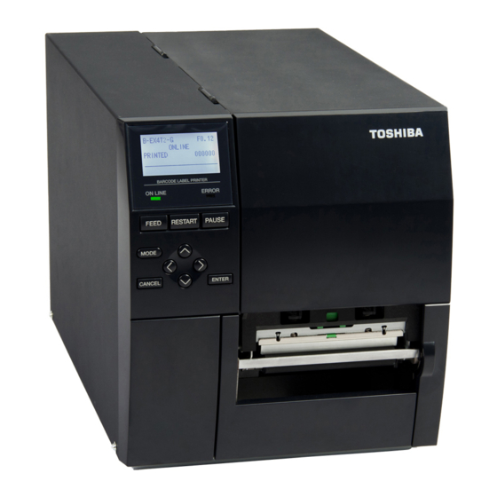
Page 4: Appearance And Dimentions (Approximate)
1. OUTLINE SPTM-0152 1.3 APPEARANCE AND DIMENSIONS (APPROXIMATE) 1.3 APPEARANCE AND DIMENSIONS (APPROXIMATE) 1.3.1 Appearance Front drawing Side drawing 1.3.2 Operation Panel Function [FEED] (1) Feeds one sheet of paper. (2) Prints the data in the image buffer on one label according to the system mode setting. - Page 5 1. OUTLINE SPTM-0152 1.3 APPEARANCE AND DIMENSIONS (APPROXIMATE) 1.3.3 Dimensions (Approximate) Color : Metal cover: Cool Black Mold cover: Cool Black Weight : B-EX4 T2 19.0Kg(acking condition) 17.0Kg(rinter only) Outside dimension : Width 278mm x Depth 460mm x Hight 310mm It is based on individual product specifications.
-
Page 6: Basic Specifications
1. OUTLINE SPTM-0152 1.4 BASIC SPECIFICATIONS 1.4 BASIC SPECIFICATIONS 1) Printing method ....Thermal direct printing or thermal transfer printing 2) Print head [GS model] (1) Total number of dots ..832 dots (3) Effective print width ..104.0 mm (2) Dot density ..... - Page 7 1. OUTLINE SPTM-0152 1.4 BASIC SPECIFICATIONS 8) Type of characters [GS model] Times Roman medium (12, 15 point) (12) Courier bold (18 point) Times Roman bold (15, 18, 21 point) (13) OCR-A, B (12 point) Times Roman Italic (18 point) (14) Outline font (Helvetica bold, Helvetica bold proportional, Helvetica medium (9, 15, 18 point) Price Font (1,2,3), Times roman proportional, Pop...
- Page 8 1. OUTLINE SPTM-0152 1.4 BASIC SPECIFICATIONS 16) Mechanism (1) Mechanism Ribbon end sensor 47.4mm Peel-off bar 13.75mm Peel-off sensor 15.3mm Label sensor 77.25mm (2) Paper Sensor Paper left edge Reflect sensor Transmissive sensor 57mm 10mm...
- Page 9 1. OUTLINE SPTM-0152 1.4 BASIC SPECIFICATIONS (3) Cutter mechanism When the cutter module is installed, the backing paper of the label stock or tag paper is cut individually. Disk cutter: Stop and cut Disk Cutter:21.9 Item Specification Cutter type DISK CUTTER Paper width 30.0mm - 25.4- 500mm...
- Page 10 1. OUTLINE SPTM-0152 1.4 BASIC SPECIFICATIONS 17) Power supply AC220 - 240 V ±10%, 50Hz CN model: AC100 - 240 V ±10%, 50/60Hz QM model: Global(QM) China(CN) AC100V-240V ± 10% AC100V-240V ± 10% Input voltage/frequency 50-60Hz 50Hz AC cord Not include Not include Power Rush current...
-
Page 11: Electronics Specifications
1. OUTLINE SPTM-0152 1.5 ELECTRONICS SPECIFICATIONS 1.5 ELECTRONICS SPECIFICATIONS 1) CPU ........R8A77211C133BGV 2) Memory (1) Program ......2 x 16MB Flash ROM (2) Image buffer + Work..2 x 16MB SDRAM Hardware Model Flash ROM SDRAM Font ROM Type Font B-EX4T2-GS12-QM-R None B-EX4T2-TS12-QM-R... - Page 12 1. OUTLINE SPTM-0152 1.5 ELECTRONICS SPECIFICATIONS 8) Protocol * XON/XOFF (DC1/DC3) protocol • When initialized after power on, this printer becomes ready to receive data and sends an XON code (11H). (Transmission or non-transmission of XON code is selectable by means of the parameter setting.) •...
- Page 13 1. OUTLINE SPTM-0152 1.5 ELECTRONICS SPECIFICATIONS 9) Pin description Pin No. Signal Description FG (Frame Ground) Ground line for circuit protection. Data line from which the printer receives data from the host (receive data line). RD (Received Data) Input Logic “1” is “Low”, and “0” is “High”. It is LOW (MARK) while no data is being sent.
- Page 14 1. OUTLINE SPTM-0152 1.5 ELECTRONICS SPECIFICATIONS (4) Centronics interface (Option) 1) Data input method: 8-bit parallel (DATA 1 to 8) 2) Control signals SPP mode: nStrobe, nAck, Busy, PError, Select, nAutoFd, nInit, nFault, nSelectIn Nibble mode: HostClk, PtrClk, PtrBusy, AckDataReq, Xflag, HostBusy, nInit, nDataAvail, IEEE1284Active 3) Data input code: ASCII, JIS 8-bit code for European characters, 8-bit code for...
- Page 15 1. OUTLINE SPTM-0152 1.5 ELECTRONICS SPECIFICATIONS (5) Expansion I/O interface (Option) Interface circuit * Input circuit There are 6 input circuits, and each input is a current loop using the photo coupler. The anode of the photo coupler of each circuit is connected to the common pin COM 1. The cathodes are independent.
- Page 16 1. OUTLINE SPTM-0152 1.5 ELECTRONICS SPECIFICATIONS (6) USBH (Option) 1) Standard: USB V2.0 2) Transfer mode: Control transfer, Bulk transfer 3) Transfer rate: Full speed (12M bps) 4) USB interface Connector: USB-Type A Power supply specification: 500mA output (7) Wireless LAN (Option) 1) Standard: IEEE802.11b/g 2) Protocol:...
-
Page 17: Supply Specifications
Detail specifications and other information on the media and ribbon are described in Supply Manual by model. It is issued by and sent from TOSHIBA TEC H.Q (Sales Division) upon release of new model or manual's revision. When purchasing the supplies locally, be sure to refer to the Supply Manual for details. - Page 18 2. SUPPLY SPECIFICATIONS SPTM-0152 2.1 MEDIA (Paper) <Labels> I Roll method: Labels facing inside H Feed direction 1.5mm 1.5mm Roll method: Labels facing outside <Tags> Black Mark(Reverse Side) Roll method: Tag facing inside H Feed direction Roll method: Tags facing outside...
- Page 19 2. SUPPLY SPECIFICATIONS SPTM-0152 2.1 MEDIA (Paper) NOTES: 1. For label issues, set the head lever to position LABEL. 2. For tag issues, set the head lever to position TAG. 3. When using narrow paper, may need to set the head lever to position TAG, or need to adjust the right head pressure.
- Page 20 2. SUPPLY SPECIFICATIONS SPTM-0152 2.1 MEDIA (Paper) 2.1.3 Detection Area on Labels and Tags 2.1.3.1 Sensor position The sensor is movable in the range from the center of the paper to the left end. Transmissive sensor and Reflective sensor are moving from side to side at same time each sensor unit.
- Page 21 2. SUPPLY SPECIFICATIONS SPTM-0152 2.1 MEDIA (Paper) <Labels> Transmissive Sensor Transmissive (Center of paper) Sensor position Necessary detection area View from the Label print side Min. 2.0 mm (Min.6.0mm Label when the cutter Paper feed is used.) direction Min. 12 mm Magnified view of detection area 16mm Transmissive sensor is...
- Page 22 2. SUPPLY SPECIFICATIONS SPTM-0152 2.1 MEDIA (Paper) 2.1.4 Effective Print Area of Paper 2.1.4.1 Relationship between Print Head Effective Print Width and Paper Width Paper Paper position position (Left) (Right) Printing area Outside 104.0mm±0.2mm Outside printing (Effective print head width) 2 mm 8 mm printing...
- Page 23 2. SUPPLY SPECIFICATIONS SPTM-0152 2.1 MEDIA (Paper) 2.1.4.3 Print Position Misalignment Printing area (1) Horizontal(Meandering) Horizontal misalignment due to repetition: A = ±1.0 mm To determine the reference value for A, make a print test 10 times or more using the specified label or tag, and adjust the Paper feed print position using the average value of...
- Page 24 2. SUPPLY SPECIFICATIONS SPTM-0152 2.1 MEDIA (Paper) 2.1.4.4 Suggestions for Designing Labels (1) Multiple-piece Labels To properly detect each label by the transmissive sensor, the necessary detecting area that is specified in section 2.3.1 should be provided. At the same time, the shaded area shown below must be non-transmissive, excluding the necessary detecting area.
- Page 25 2. SUPPLY SPECIFICATIONS SPTM-0152 2.1 MEDIA (Paper) (3) Perforation Labels and tags must always be perforated from the printing side. Note) At present time, Fanfold paper has not been certified. If using Fanfold paper, paper retainer should be required. (4) Preprinting The print head may be abnormally worn depending on the ink to be used.
- Page 26 2. SUPPLY SPECIFICATIONS SPTM-0152 2.1 MEDIA (Paper) 2.1.5 Approved Paper Paper Manufacturer Type Item Code Manufacturer Remarks Thickness Type No. (µm) Direct 150LA-1P RICOH thermal type Vellum Raflatac (Uncoated) Transtherm 1C Fasson (Coated, gloss) OSAKA SEALING Label VES-85 (Yupo) PRINTING Thermal transfer FR1412-50...
-
Page 27: Ribbon
2. SUPPLY SPECIFICATIONS SPTM-0152 2.2 RIBBON 2.2 RIBBON 2.2.1 Ribbon The approved ribbon must be used. Use of any non-approved ribbon may cause problems. 2.2.2 Shape and Size of Ribbon Item Specification Ribbon Shape Spool type Ribbon Width 68(40) ±1 mm to 112 mm Ribbon Winding Width 68(40) mm to 112 mm... - Page 28 2. SUPPLY SPECIFICATIONS SPTM-0152 2.2 RIBBON Fig. 2: Positional Relationship between Core and Ribbon The inked surface faces the outside. NOTE: Wind the ink ribbon so that the ribbon center aligns with the core center. Fig. 3: Connection between Leader Tape and Ribbon Leader Adhesive Adhesive...
- Page 29 2. SUPPLY SPECIFICATIONS SPTM-0152 2.2 RIBBON 2.2.3 NOTES on using ribbon If the difference between the ribbon width and the paper width is too large, the ribbon may wrinkle. Refer to the table below and choose the paper appropriate to the ribbon width. Even if the ribbon is narrower than paper, printing can be performed.
- Page 30 2. SUPPLY SPECIFICATIONS SPTM-0152 2.2 RIBBON 2.2.5 NOTES 2.2.5.1 If printing is performed using only a narrow range of the ribbon as shown below, the ribbon may wrinkle. ABCDEF ABCDEF ABCDEF ABCDEF ABCDEF ABCDEF ABCDEF ABCDEF ABCDEF ABCDEF ABCDEF ABCDEF ABCDEF ABCDEF ABCDEF...
-
Page 31: Care And Handling Of The Media And Ribbon
2. SUPPLY SPECIFICATIONS SPTM-0152 2.3 CARE AND HANDLING OF THE MEDIA AND RIBBON 2.3 CARE AND HANDLING OF THE MEDIA AND RIBBON CAUTION! Be sure to read carefully and understand the Supply Manual. Use only media and ribbon which meet specified requirements. Use of non-specified media and ribbon may shorten the head life and result in problems with bar code readability or print quality. -
Page 32: Print Conditions
2. SUPPLY SPECIFICATIONS SPTM-0152 2.4 PRINT CONDITIONS 2.4 PRINT CONDITIONS 2.4.1 Print Quality of Bar Code Head Bar code Speed Criteria Resolution 3”/sec Grade B 6”/sec Grade B 203dpi 10”/sec Grade C 12”/sec Grade C 3”/sec Grade B 5”/sec Grade B 300dpi 8”/sec Grade C... - Page 33 2. SUPPLY SPECIFICATIONS SPTM-0152 2.4 PRINT CONDITIONS 2.4.2 PRINT QUALITY OF QR CODE Head Resolution Speed 1 cell Criteria 3”/sec 3 dots or more Grade D 6”/sec 4 dots or more Grade D 203dpi 10”/sec 4 dots or more Readable 12”/sec 4 dots or more Readable...
-
Page 34: Specification Of Rfid Tag (For B-Ex700-Rfid-H1-Qm-R)
2. SUPPLY SPECIFICATIONS SPTM-0152 2.5 SPECIFICATION OF RFID TAG (for B-EX700-RFID-H1-QM-R) 2.5 SPECIFICATION OF RFID TAG (for B-EX700-RFID-H1-QM-R) 2.5.1 General Description The RFID supplies are RFID tag (wireless IC tag) inlays designed to be converted into tag and label applications. Printers, which are equipped with an RFID kit, can print data on the surface of RFID tags as well as write data on them. - Page 35 2. SUPPLY SPECIFICATIONS SPTM-0152 2.5 SPECIFICATION OF RFID TAG (for B-EX700-RFID-H1-QM-R) 5) Cutter When an RFID label or tag is used in cut issue mode, care must be taken not to cut an antenna of the RFID tag or an IC chip in order not to damage the cutter. 6) Static Electricity When printing is performed in a place where humidity is low or under some specific conditions, writing data on an RFID tag may fail due to static electricity generated by a label or a ribbon.
- Page 36 2. SUPPLY SPECIFICATIONS SPTM-0152 2.5 SPECIFICATION OF RFID TAG (for B-EX700-RFID-H1-QM-R) 10) Strip Issue Stripping performance in strip issue mode depends on the type of glue, tag, and backing paper. For some RFID supplies used, an issue may not be performed properly in strip issue mode. 11) Caution for Minimum Label Pitch Length When media, of which label pitch length is short, is used, data may be written on an RFID tag next to the target RFID tag.
-
Page 37: Specification Of Rfid Tag (For B-Ex700-Rfid-U2-Eu-R)
2. SUPPLY SPECIFICATIONS SPTM-0152 2.6 SPECIFICATION OF RFID TAG (for B-EX700-RFID-U2-EU-R) 2.6 SPECIFICATION OF RFID TAG (for B-EX700-RFID-U2-EU-R) 2.6.1 General Description The RFID supplies are RFID tag (wireless IC tag) inlays designed to be converted into tag and label applications. Printers, which are equipped with an RFID kit, can print data on the surface of RFID supplies as well as write data on the embedded RFID tags. - Page 38 2. SUPPLY SPECIFICATIONS SPTM-0152 2.6 SPECIFICATION OF RFID TAG (for B-EX700-RFID-U2-EU-R) 2.6.5 Cautions for using RFID Tags 1) Lift-up of Print Head An RFID tag chip or the thermal head may be damaged when the thermal head passes over the chip.
- Page 39 2. SUPPLY SPECIFICATIONS SPTM-0152 2.6 SPECIFICATION OF RFID TAG (for B-EX700-RFID-U2-EU-R) 7) Printing on Bump (Chip/Antenna) Area Embedding RFID tags in labels creates bumps in a chip/antenna area in the labels, causing incomplete printing. Especially, in the areas 5 mm from and left and right sides of the RFID-tag embedded area shown in the figure below, uneven printing or incomplete printing can occur easily.
- Page 40 2. SUPPLY SPECIFICATIONS SPTM-0152 2.6 SPECIFICATION OF RFID TAG (for B-EX700-RFID-U2-EU-R) 11) Defective RFID Tag Defective tags could be embedded while they are converted into labels, and the error rate differs depending on the tag types or the conversion methods. Label manufacturers should mark such defective labels with something to indicate the tag is defective, or should prevent defective tags from being used.
-
Page 41: Specification Of Rfid Tag (For B-Ex700-Rfid-U2-Us-R)
2. SUPPLY SPECIFICATIONS SPTM-0152 2.7 SPECIFICATION OF RFID TAG (for B-EX700-RFID-U2-US-R) 2.7 SPECIFICATION OF RFID TAG (for B-EX700-RFID-U2-US-R) 2.7.1 General Description The RFID supplies are RFID tag (wireless IC tag) inlays designed to be converted into tag and label applications. Printers, which are equipped with an RFID kit, can print data on the surface of RFID supplies as well as write data on the embedded RFID tags. - Page 42 2. SUPPLY SPECIFICATIONS SPTM-0152 2.7 SPECIFICATION OF RFID TAG (for B-EX700-RFID-U2-US-R) After printing a label, a reverse feed for a distance equivalent to one label pitch is required to write data onto its tag. During this reverse feed, the bottom edge of the printed label may be stuck on the print head edge, causing a feed jam.
- Page 43 2. SUPPLY SPECIFICATIONS SPTM-0152 2.7 SPECIFICATION OF RFID TAG (for B-EX700-RFID-U2-US-R) 7) Printing on Bump (Chip/Antenna) Area Embedding RFID tags in labels creates bumps in a chip/antenna area in the labels, causing incomplete printing. Especially, in the areas 5 mm from and left and right sides of the RFID-tag embedded area shown in the figure below, uneven printing or incomplete printing can occur easily.
- Page 44 2. SUPPLY SPECIFICATIONS SPTM-0152 2.7 SPECIFICATION OF RFID TAG (for B-EX700-RFID-U2-US-R) 11) Defective RFID Tag Defective tags could be embedded while they are converted into labels, and the error rate differs depending on the tag types or the conversion methods. Label manufacturers should mark such defective labels with something to indicate the tag is defective, or should prevent defective tags from being used.
-
Page 45: Specification Of Rfid Tag (For B-Ex700-Rfid-U2-Cn-R)
A short-pitch tag kit is supplied with the B-EX700-RFID-U2-CN-R to enable the RFID kit to encode short-pitch tags properly. However, an adjustment will be necessary for each type of short-pitch tags individually. When short- pitch tags are used, consult TOSHIBA TEC Japan. 2.8.5 Cautions for using RFID Tags 1) Lift-up of Print Head An RFID tag chip or the thermal head may be damaged when the thermal head passes over the chip. - Page 46 2. SUPPLY SPECIFICATIONS SPTM-0152 2.8 SPECIFICATION OF RFID TAG (for B-EX700-RFID-U2-CN-R) 5) Cutter When an RFID label or tag is used in cut issue mode, care must be taken not to cut the antenna or the IC chip of an RFID tag in order not to damage the cutter. 6) Static Electricity When printing is performed in a place where humidity is low or under some specific conditions, writing data on an RFID tag may fail due to static electricity generated by a label or a ribbon.
- Page 47 2. SUPPLY SPECIFICATIONS SPTM-0152 2.8 SPECIFICATION OF RFID TAG (for B-EX700-RFID-U2-CN-R) 10) Caution for minimum label pitch length When short-pitch media is used, data may be written on a next RFID tag instead of the target RFID tag. As the location, where data is to be written, differs among RFID tag types, a check must be performed using the labels to be used to make sure that the data is written on the target RFID tags.
-
Page 48: Optional Kit
Installing this PC board allows a B-EX700-WLAN-QM-R All models LAN Module communication by wireless LAN. Parallel I/F B-EX700-CEN-QM-R All models card Serial I/F B-EX700-RS-QM-R All models card NOTE: To purchase the optional kits, please contact the TOSHIBA TEC Head Quarters. -
Page 49: Cutter Module: B-Ex204-Qm-R (Disk Cutter)
3. OPTIONAL KIT SPTM-0152 3.1 CUTTER MODULE: B-EX204-QM-R (Disk Cutter) 3.1 CUTTER MODULE: B-EX204-QM-R (Disk Cutter) This compact cutter module uses a built-in disk cutter. The specification is provided below: 1) Disc cutter module: Paper Specifications Contents Specification Label Paper length 12 to 1500mm Cut width 15 to 120mm Label width 13 to 117mm Gap length 2 to 20mm... - Page 50 3. OPTIONAL KIT SPTM-0152 3.2 PEEL OFF MODULE: B-EX904-H-QM-R 3.2 PEEL OFF MODULE: B-EX904-H-QM-R This strip module consists of the take-up block and the strip block. Installing the strip module enables the printer to not only remove labels from the backing paper, but wind the tag paper or label with backing paper onto the take-up spool by using the rewinder guide plate.
-
Page 51: Peel Module: B-Ex904-H-Qm-R
3. OPTIONAL KIT SPTM-0152 3.2 PEEL OFF MODULE: B-EX904-H-QM-R Performance: Notes: Refer to B-EX supply specifications (RAA-1396) for the conditions of Peel-off issue. Liner paper width 30 to 120mm Label width 27 to 117mm Label length *1 23.4 to 1494.0mm Max Print speed *2 203dpi: Max 6ips 305(300) dpi: Max 5ips... -
Page 52: Rtc/Usb Host Interface Board: B-Ex700-Rtc-Qm-R
3. OPTIONAL KIT SPTM-0152 3.3 EXPANSION I/O CARD: B-EX700-IO-QM-R 3.3 EXPANSION I/O CARD: B-EX700-IO-QM-R This interface board is used to connect the printer to external devices, such as a labeler. The input/output signals from the connected external devices can control label feeding or printing and indicate the print status. -
Page 53: Applicable Model
3. OPTIONAL KIT SPTM-0152 3.6 RFID MODULE: B-EX700-RFID-U2-EU/US/CN-R 3.6 RFID MODULE: B-EX700-RFID-U2-EU/US/CN-R Installing this module enables the printer to write data on an RFID tag as well as to print on the surface of RFID supplies. Applicable model: This optional device is intended for the following models: B-EXT1-GS12-QM-R and B-EXT1-GS12-CN-R, RFID ready printer. - Page 54 US (Serial Number 2808Yxxxxxx and earlier): TOSHIBA TEC TRW-USM-01 for U.S.A. and Canada Module US (Serial Number 2809Axxxxxx or earlier): TOSHIBA TEC TRW-USM-01 for U.S.A., Canada, Australia, South Korea, Taiwan CN: TOSHIBA TEC TRW-CNM-01 for CHina EU: ETSI EN 300 220 AU: C-Tick AS.NZS 428(2003);...
-
Page 55: Country Code
3. OPTIONAL KIT SPTM-0152 3.7 WIRELESS LAN BOARD: B-EX700-WLAN-QM-R WIRELESS LAN BOARD: B-EX700-WLAN-QM-R Country code: Be sure to set the country code beforehand because the frequency band differs depending on the country. Please ask end-users to confirm the country code setting. Using the printer with wrong country code may conflict with the radio law of each country, causing a penalty. - Page 56 3. OPTIONAL KIT SPTM-0152 3.7 WIRELESS LAN BOARD: B-EX700-WLAN-QM-R MAC Address: MAC address is described on the wireless LAN module and the accessory sticker. It is required when using the MAC address filtering function of the Access Point (AP). Please describe it in the installation manual, etc.
- Page 57 3. OPTIONAL KIT SPTM-0152 3.7 WIRELESS LAN BOARD: B-EX700-WLAN-QM-R NOTES: 1. The printer constantly performs communication with cordless handset in Adhoc mode, therefore, the consumption current in standby status increases, causing the time available of the battery pack to be reduced.
Need help?
Do you have a question about the B-EX4 T1 Series and is the answer not in the manual?
Questions and answers